Special tool
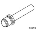 | Bearing outer ring and oil seal installer 204-017 (14-010) |
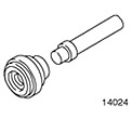 | Bearing outer race and oil seal installer 204-050 (14-024) |
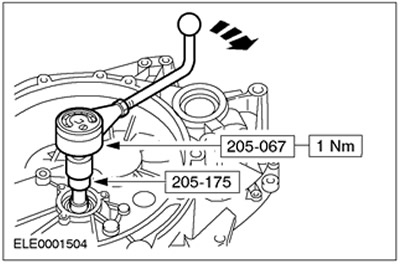
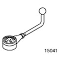 | Torque Gauge 205-067 (15-041) |
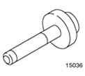 | Bearing outer ring installer 205-075 (15-036) |
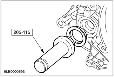
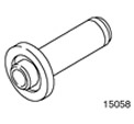 | Differential Oil Seal Installer 205-115 (15-058) |
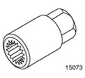 | Socket head 205-175 (15-073) |
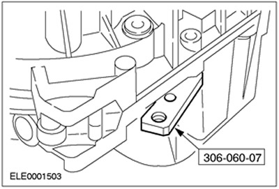
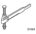 | Valve Spring Compressor 306-060 (21-024) |
 | Adapter for 306-060 306-060-02 (21-024-02) |
 | Adapter for 306-060 306-060-07 (21-024-07) |
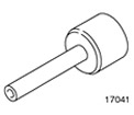 | Input Shaft Oil Seal Installer 307-210 (17-041) |
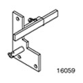 | Device for measuring the axial clearance of the input shaft 308-194 (16-059A) |
General equipment:
- Press
- Dial indicator
- Tripod with magnetic base for dial indicator
- steel plate (e.g. 303-435-11 (21-146C))
| Name | Specification |
| transmission fluid | WSD-M2C200-C |
| sealant | WSK-M2G348-A5 |
| Sealant for clutch slave cylinder | ESK-M4G269-A |
| High temperature grease | ESDM-1C220-A |
Assembly
All cars
1.
NOTE: The 1.8L Endura-DI has been available since MY 1999.
Carefully clean and check all elements before assembly.
- Lubricate all work surfaces. For this purpose, transmission fluid is used.
2.
NOTE: Only if removed
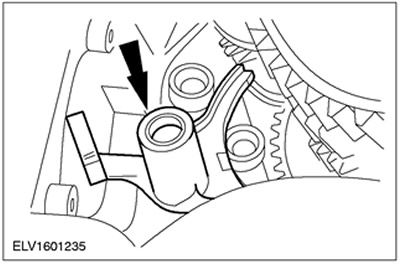
Install the reverse gear shaft.
- 1. Apply sealant to the mating surface of the reverse idle gear axle.
- 2. Align the position of the shaft of the intermediate gear of the reverse gear with the set bolt and install it in place.
- 3. Turn out an adjusting bolt and screw in original bolts.
3.
CAUTION: The maximum press force is 15 kN.
Install the bearing inner races from the gearbox housing side.
- Using a hot air gun, heat the crankcase area to approximately 80°C.
- Cool the inner races of the bearings using a temperature-reducing spray and install them.
- Install the bearing inner races:
- input shaft using special tool 307-210 (17-041)
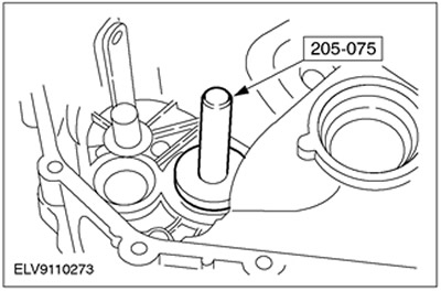
- output shaft using special tool 205-075 (15-036)
- differential using special tool 204-050 (14-024)
4. Gauge gasket to be installed on:
- input shaft: 1.00 mm
- secondary shaft: 1.00 mm
- differential: 1.10 mm
5.
CAUTION: Maximum press force: 15 kN.
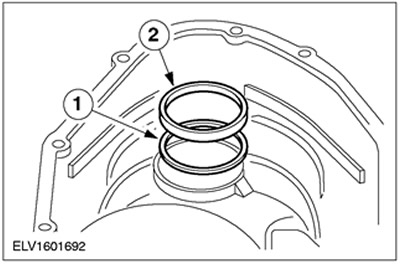
Install shims and bearing cones into the crankcase section on the clutch side.
- Heat the crankcase area to approximately 80°C using a hot air gun.
- Cool the bearing inner races using a temperature reducing spray.
- 1. Install shims.
- 2. Install the bearing inner races.
- Install the bearing inner races:
- input shaft using special tool 204-017 (14-010)
- output shaft using special tool 205-075 (15-036)
- differential using special tool 204-050 (14-024)

6.
NOTE: Do not apply oil to reusable tapered roller bearings. Install new tapered roller bearings (raw).
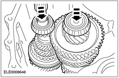
Insert the input and output shafts into the gearbox housing.
- Engage fourth gear.
- Assemble the input and output shafts and insert them together into the gearbox housing.
7.
NOTE: Do not apply oil to tapered roller bearings that are to be reused. Install new tapered roller bearings (raw).
Insert Differential (1.8 Endura-DI shown).
8.
NOTE: Check if the mating surface is clean.
Install the crankcase section (clutch side).
- Install the special tool along with the longest bolt on the transaxle housing flange.
9. Install the crankcase section (clutch side). Tighten the 16 flange bolts evenly.
10. Install the special tool.
- Move the measuring plunger to the fourth gear.
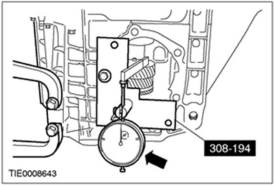
11. Prepare input shaft for measurements.
- Rotate the input shaft back and forth approximately 20 times to allow the bearings to settle into a stable position.
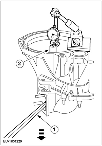
12. Install the dial indicator.
- 1. Connect the steel plate (e.g. 303-435-11 (21-146C)) to the gearbox.
- 2. Set up a tripod with a magnetic dial indicator base.
- 3. Set the dial indicator to «0».
13.
NOTE: Repeat the previous step and this step three times and calculate the average.
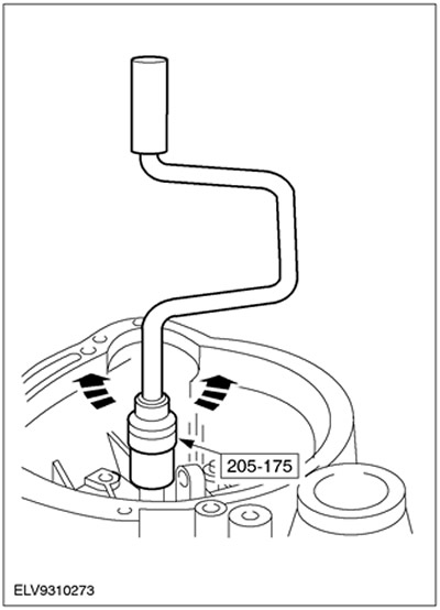
Measure input shaft end play.
- 1. Raise the input shaft with the mounting key.
- 2. Record the result (e.g. 0.22 mm).
- Example: 0.22mm + 0.23mm + 0.21mm divided by 3 = 0.22mm.
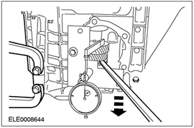
14. Prepare the output shaft for measurements.
- Rotate the output shaft back and forth 20 times to allow the bearings to settle into a stable position (see previous point).
- Install a dial indicator.
- Set the dial indicator to «0».

15.
NOTE: Do this and the next step three times and calculate the average.
Measure the output shaft end play.
- Raise the output shaft using a balloon wrench and record the result, eg 0.32 mm.
- Example: 0.32mm + 0.34mm + 0.33mm divided by 3 = 0.33mm.
16. Prepare differential for measurements.
- Rotate the input shaft back and forth 20 times and simultaneously press down on the differential.
- Install a dial indicator and set it to «0».
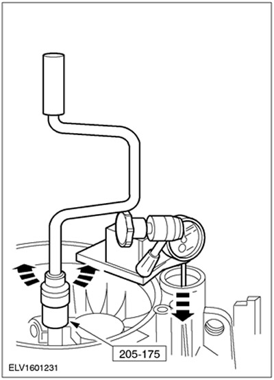
17.
NOTE: Do this and the next step three times and calculate the average.
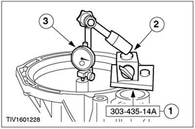
Measure differential end play
- Raise the differential using the special tool and record the measurement, e.g. 0.34 mm
- Example: 0.34mm + 0.36mm + 0.38mm divided by 3 = 0.36mm.
18. Calculate the required input shaft shim thickness.
- Required gasket thickness 1.00 mm
- Measured axial clearance (see previous point) 0.22 mm.
- Axial clearance - 0.05 mm
- Required gasket thickness: 0.22mm -0.05mm + 1.00mm = 1.17mm.
19. Calculate the required output shaft shim thickness.
- The required gasket thickness is 1.00 mm.
- Measured axial clearance (see previous point) 0.33 mm.
- Preload 0.13 mm.
- Required gasket thickness: 1.00 mm + 0.33 mm + 0.13 mm = 1.46 mm.
20. Calculate the required differential gasket thickness.
- The required gasket thickness is 1.10 mm.
- Measured axial clearance (see previous point) 0.36mm
- Preload 0.33 mm.
- Required gasket thickness: 1.10 mm + 0.36 mm + 0.33 mm = 1.79 mm.
21. Remove the inner races of the bearings again.
- Remove bearing inner races:
- input shaft
- output shaft
- differential
22. Install shims and bearing inner races.
- 1. Install shims of the required thickness.
- 2. Install the bearing inner races.
- input shaft
- output shaft
- differential
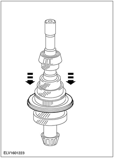
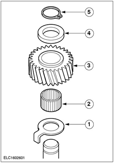
23. Install the reverse idle gear.
- 1. Bottom thrust washer
- 2. Needle roller bearing
- 3. Reverse Gear (smaller ring facing down)
- 4. Upper thrust washer
- 5. Retaining ring
24. Establish together primary and secondary shafts.
- Lubricate tapered roller bearings with gear oil.
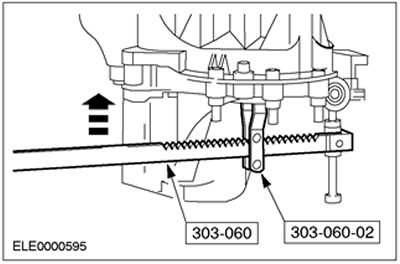
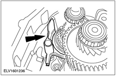
25. Install the gear selection fork.
- Move the 4th gear synchronizer clutch to the neutral position.
- Insert the 5th gear and reverse gear selector fork and tilt it to the side.
26. Install the third and fourth gear selection fork.
- Move the fork for selecting the fifth gear and reverse gear back.
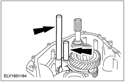
27.
NOTE: Properly installed selector shafts will be at the same height.
Install the 1st and 2nd gear selector forks and selector shafts.
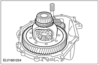
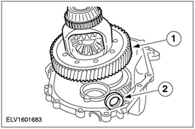
28. Install differential (1.8 Endura-DI shown).
- 1. Install differential assembly.
- 2. Place a blank magnetic disk into the recess.
29. Apply sealant to the mating surface.
- Sealing surfaces must be dry and free of oil. Apply sealant evenly to the inside of the sealing surface (uniform roller with a diameter of 2 mm).
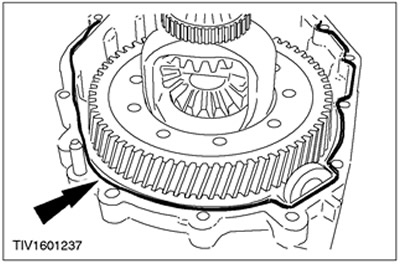
30.
NOTE: The transmission must not be reversed to tighten the crankcase bolts.
Install crankcase (clutch side).
- Tighten the 16 flange bolts within 15 minutes, working in a criss-cross pattern.
Vehicles manufactured up to 01.2000
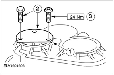
31.
NOTE: Make sure the transmission is in neutral (the shift lever and gear select lever must be in the vertical position.
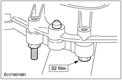
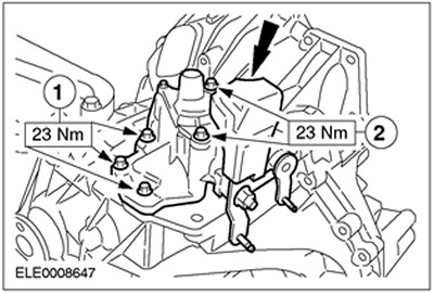
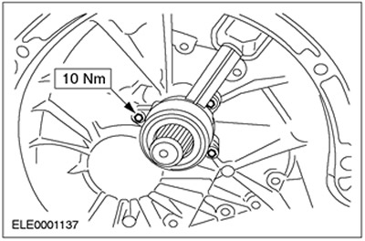
Install the gear selector.
- Sealing surfaces must be dry and free of oil. Apply sealant evenly to the outside of the sealing surface (uniform roller with a diameter of 2 mm).
- 1. Bolt, M8x35 mm
- 2. Bolt, М8х85 mm
Vehicles manufactured since 02.2000
32.
NOTE: Make sure the transmission is in neutral (the shift lever and gear select lever must be in the vertical position.
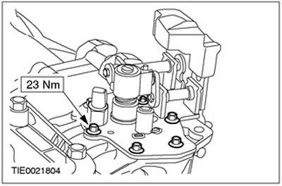
Install the gear selector.
- Sealing surfaces must be dry and free of oil. Apply sealant evenly to the outside of the sealing surface (uniform roller with a diameter of 2 mm).
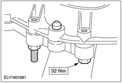
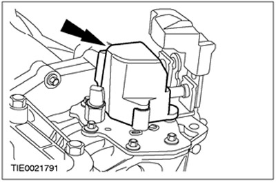
33. Install the shifter cover.
All cars
34. Measure the turning moment.
- Engage fourth gear.
- Measure the turning moment.
- If the cranking torque is too high, all measurements (to determine the required gasket thickness) should be repeated.
Diesel vehicles
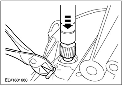
35. Install the speedometer drive gear.
- Insert the drive gear.
- Carefully insert the pin.
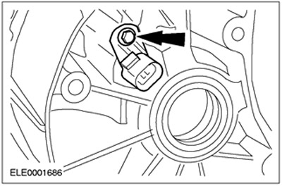
Vehicles with 2.0L engine
36. Install the vehicle speed sensor (VSS).
All cars
37. Install the front axle oil seals.
38.
WARNING: Do not allow brake fluid to come into contact with skin or eyes. If brake fluid comes into contact with the skin or eyes, immediately flush the affected area with water. Failure to follow this instruction may result in injury.
CAUTION: Apply adhesive tape to the input shaft splines to prevent damage to the input shaft seal.
CAUTION: Do not lubricate the clutch slave cylinder.
NOTE: Install a new clutch slave cylinder.
Install the clutch slave cylinder using a new seal and slave cylinder sealant.
39. Remove adhesive tape from input shaft splines.
40. Apply a thin layer of high temperature grease to the input shaft splines.
Visitor comments