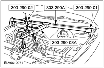
Special tool
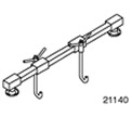 | Engine support beam 303-290A (21-140A) |
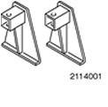 | Adapter for 303-290A (21-140) 303-290-01 (21-140-01) |
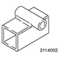 | Adapter for 303-290A (21-140) 303-290-02 (21-140-02) |
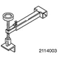 | Adapter for 303-290A (21-140) 303-290-03A (21-140-03A) |
General equipment:
- Jack for gearbox
- Fixing clamp
Installation
All cars
1. General note: Use only new self-locking nuts.
2. Raise the vehicle. Refer to Section 100-02 for more information.
3. Secure the transmission using a tie-down clamp and wooden blocks to the transmission jack.
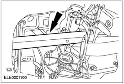
4. Slide the engine forward and insert a 350 mm piece of wood between the engine and subframe.
- Move the gearbox to the required position.

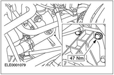
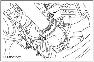
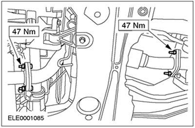
5. Install the bottom flange bolts.
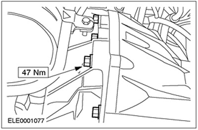
6. Install the bottom flange bolts.

7. Move the engine and transmission forward and remove the wood block.
8. Release the fixing clamp on the gearbox and remove the gearbox jack.
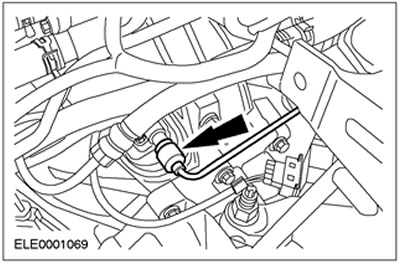
9. Connect the vehicle speed sensor connector (VSS).
10. Lower the car.
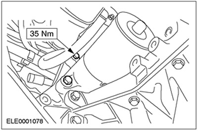
11. Install the top two flange bolts.
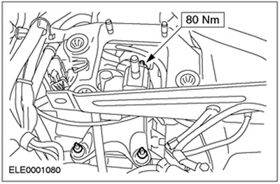
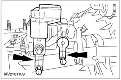
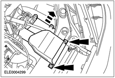
12. Install the starter. Insert three bolts (two bolts shown).
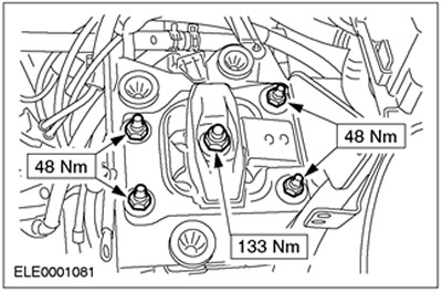
13. Install the rear engine mount bracket.
14. Slightly lift the engine/gearbox assembly using special tool 303-290A.
15. Install the rear engine mount.
16. Disconnect the special tool (battery shown in installed position).
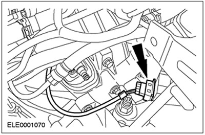
17. Connect the reversing light switch connector.
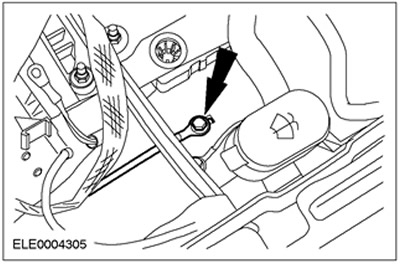
18.
WARNING: Brake fluid leakage. Do not allow brake fluid to come into contact with skin or eyes. If brake fluid comes into contact with the skin or eyes, immediately rinse the affected area with water.
CAUTION: If brake fluid comes into contact with the paintwork, immediately wash the affected area with water.
Connect the high pressure line to the clutch slave cylinder. Install the clamp.
19. Raise the vehicle. Refer to Section 100-02 for more information.
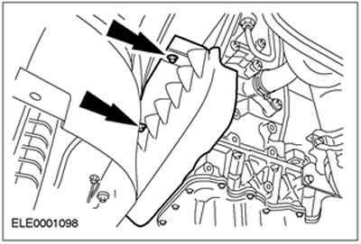
20. Install the drive belt cover.
Vehicles manufactured up to 10.2001
21.
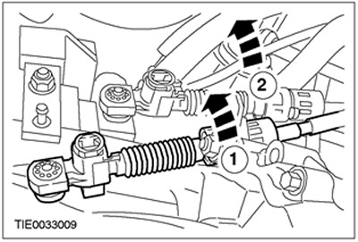
NOTE: The shift cable is marked white.
NOTE: The selector cable is marked black.
Connect shift cables to bracket.
- 1. Release the support bracket by turning it counterclockwise and connect the shift cable.
- 2. Release the support bracket by turning it counterclockwise and connect the gear selection cable.
22.
NOTE: The shift/select levers are in the neutral position when they are vertical.
Move the shift/selection levers to the neutral position.
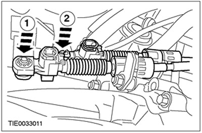
23. Connect the shift cables to the shift lever.
- 1. Connect the shift cable to the shift lever.
- 2. Connect the gear selection cable to the gear lever.
Vehicles manufactured since 10.2001
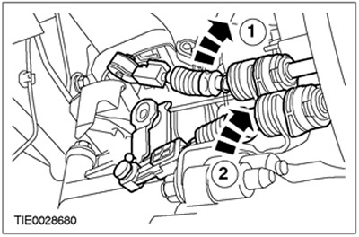
24.
NOTE: The shift cable is marked white.
NOTE: The selector cable is marked black.
Connect shift cables to bracket.
- 1. Release the support bracket by turning it counterclockwise and connect the shift cable.
- 2. Release the support bracket by turning it counterclockwise and connect the gear selection cable.
All cars
25.
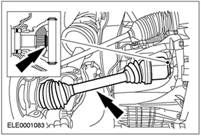
CAUTION: The inner hinge must not be tilted more than 18 degrees, the outer hinge must not be tilted more than 45 degrees.
NOTE: Use new nuts and a new intermediate bearing cap.
Establish the right semiaxle of the forward leading bridge together with an intermediate shaft.
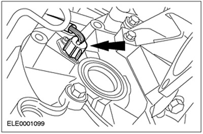
26.
CAUTION: The inner hinge must not be tilted more than 18 degrees, the outer hinge must not be tilted more than 45 degrees.
NOTE: The new circlip snaps into position.
Establish the left half shaft of the forward leading bridge (subframe shown in removed position).
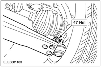
27. Install the lower suspension arm. Install a heat shield.
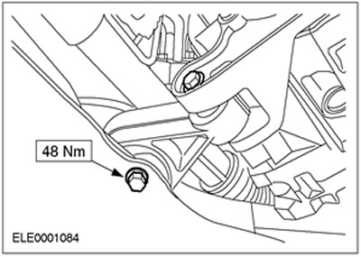
28. Install the engine roll limiter.
29. Install flexible exhaust pipe.
30. Lower the car.
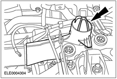
31.
NOTE: The resonator is fixed in the bracket.
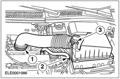
Install the air filter intake pipe with the resonator.
32. Install the inlet pipeline.
33. Connect the ground cable.
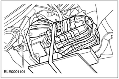
34. Install the air filter housing.
- Insert the air filter housing into the rubber bushings.
- 1. Connect the inlet hose.
- 2. Install the crankcase ventilation hose.
3. Connect the plug connector of the mass air flow sensor (MAF sensor).
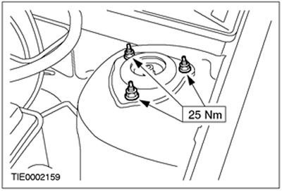
35. Tighten the suspension strut nuts on both sides.
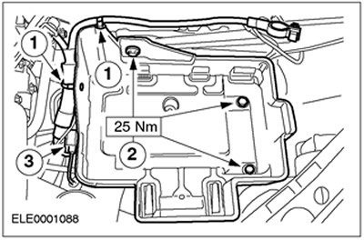
36. Install the battery shelf.
- 1. Connect the wiring harness.
- 2. Screw in the bolts.
- 3. Connect the plug connector and fix it.
37. Bleed the clutch fluid. Refer to Section 308-00 for more information.
38. Adjust shift cables. Refer to Section 308-00 for more information.
39. Install battery. Refer to Section 414-01 for more information.
40. Standard final operations.
- Check fluid levels and correct if necessary.
- Check the wiring of the vacuum hoses and electrical wiring and secure them with clamps.
- Enter the radio key code.
- Reprogram preset radios.
- Set your clock.
- Perform a road test to give the powertrain control module (RSM) opportunity to collect data.
- Check fluid levels again and correct if necessary.
Visitor comments