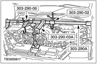
Special tool
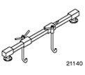 | Engine support beam 303-290A (21-140A) |
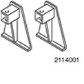 | Adapter for 303-290A (21-140) 303-290-01 (21-140-01) |
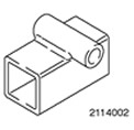 | Adapter for 303-290A (21-140) 303-290-02 (21-140-02) |
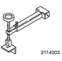 | Adapter for 303-290A (21-140) 303-290-03A (21-140-03A) |
 | Adapter for 303-290A (21-140) 303-290-06 (21-140-06) |
General equipment:
- Jack for gearbox
- Fixing clamp
Installation
All cars
1. General note: Use only new self-locking nuts.
2. Move the gearbox to the desired position using a gearbox jack and secure the gearbox using wooden blocks and a fixing collar.
3. Slide the engine/gearbox assembly forward and insert a 350mm piece of wood between the engine and subframe.
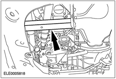
4. Install the bottom flange bolts.
5. Install the bottom flange bolts.
6. Lower the car.
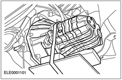
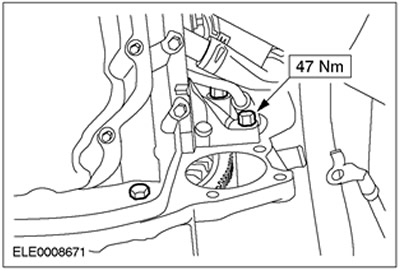
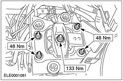
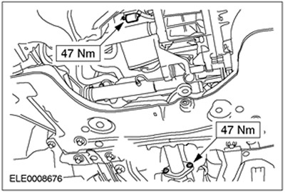
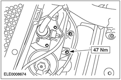
7. Install the rear engine mount bracket.
8. Lift the engine/gearbox assembly using special tool 303-290A.
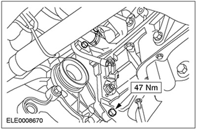
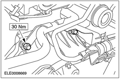
9. Install the rear engine mount.
10. Disconnect special tools.
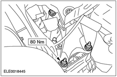
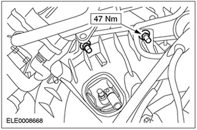
11. Install the top flange bolts.
12. Connect the pipeline of a cooling liquid to a transmission.
- Install the bracket to the transmission harness connector.
13.
WARNING: Brake fluid leakage. Avoid contact of brake fluid with skin and eyes. If brake fluid comes into contact with the skin or eyes, immediately flush the affected area with water.
CAUTION: If brake fluid comes into contact with the paintwork, immediately wash the affected area with water.
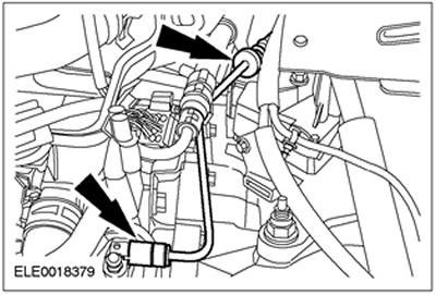
Connect the high pressure line to the clutch slave cylinder.
- Insert the pressure pipe into the bracket.
- Install the clamp.
14. Raise the vehicle. Refer to Section 100-02 for more information.
Vehicles manufactured up to 10.2001
15.
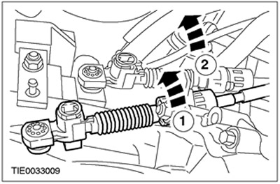
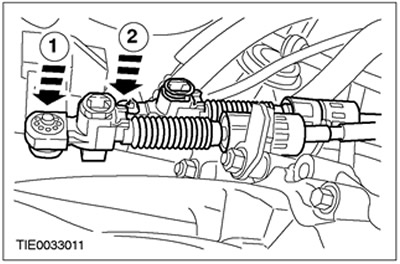
NOTE: The shift cable is marked white.
NOTE: The selector cable is marked black.
Connect shift cables to bracket.
- 1. Release the support bracket by turning it counterclockwise and connect the shift cable.
- 2. Release the support bracket by turning it counterclockwise and connect the gear selection cable.
16.
NOTE: The shift/select levers are in the neutral position when they are vertical.
Move the shift/selection levers to the neutral position.
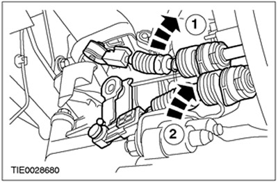
17. Connect the shift cables to the shift lever.
- 1. Connect the shift cable to the shift lever.
- 2. Connect the gear selection cable to the gear lever.
Vehicles manufactured since 10.2001
18.
NOTE: The shift cable is marked white.
NOTE: The selector cable is marked black.
Connect shift cables to bracket.
- 1. Release the support bracket by turning it counterclockwise and connect the shift cable.
- 2. Release the support bracket by turning it counterclockwise and connect the gear selection cable.
All cars
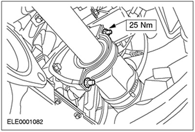
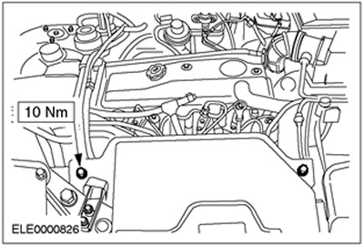
19. Install the engine roll limiter.
20. Install catalytic converter with flexible exhaust pipe. Refer to Section 309-00 for more information.
21.
CAUTION: The inner hinge must not be tilted more than 18 degrees. External hinge - at an angle exceeding 45 degrees.
NOTE: Use new nuts and a new intermediate bearing cap.
Establish the right semiaxle together with an intermediate shaft.
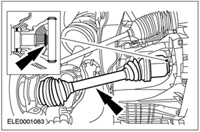
22.
CAUTION: The inner hinge must not be tilted more than 18 degrees, the outer hinge must not be tilted more than 45 degrees.
NOTE: Install a new retaining ring.
Install the left axle (shown with subframe removed).
23. Install the starter.
24.
CAUTION: Do not damage the case.
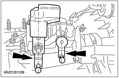
Connect both lower control arms and the vehicle's left anti-roll bar link arm (left side shown).
- Install a heat shield.
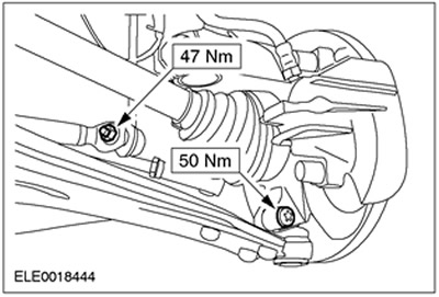
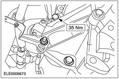
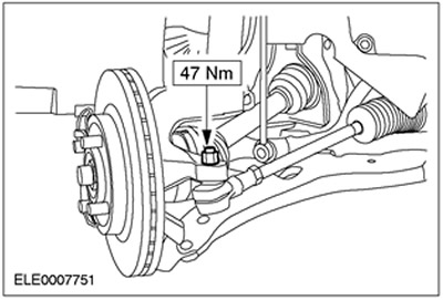
25. Establish a tip of steering draft on the left rotary fist.
- Lock the tie rod end nut with a cotter pin.
26. Install the drive belt cover.
- Install engine protection (nine bolts) (in the presence of).
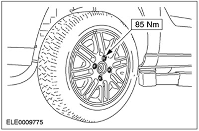
27. Install the left front wheel.
28. Lower the car.
29. Connect the catalytic converter to the exhaust manifold.
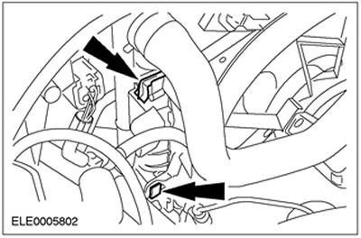
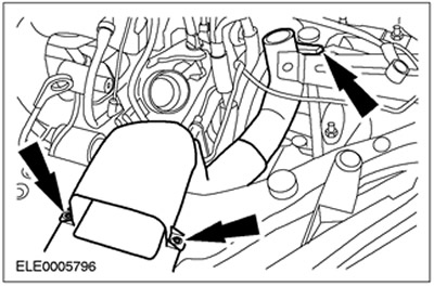
30. Install blower fan.
- Insert the blower and secure the clips on both sides.
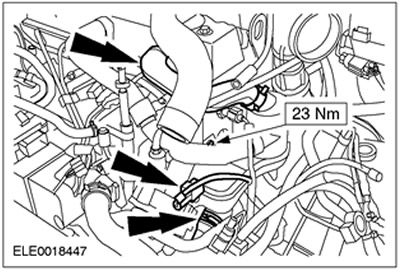
31. Connect an arm for the pipeline of a high pressure of the amplifier of a steering.
32. Connect the male connectors.
- Vehicle speed sensor (VSS)
- transmission wiring harness
- Reversing light switch
33. Fix the wiring harness and Dock the plug connector of the fan motor.
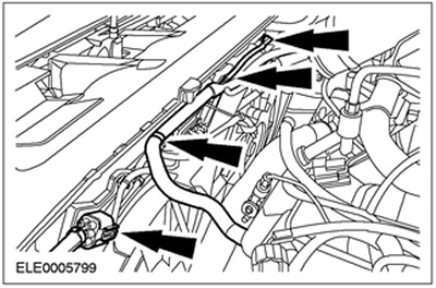
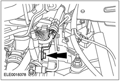
34. Install the crankcase ventilation oil separator.
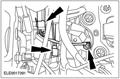
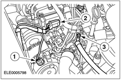
35. Dock the plug connector and connect the wires of the glow plugs.
- 1. Alternator connector
- 2. High pressure fuel pump connector
- 3. Wire glow plug
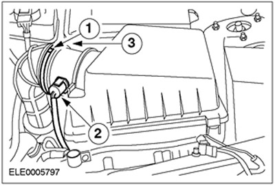
36. Install air intake piping.
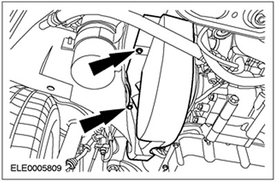
37. Install the air filter housing.
- 1. Install hose clamps.
- 2. Connect the plug connector.
- 3. Connect the vacuum hose.
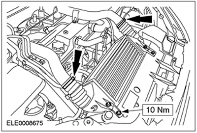
38. Install the intercooler.
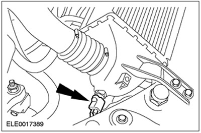
39. Install the connector for the air intake temperature sensor (IAT).
40. Connect an air duct of an intermediate cooler.
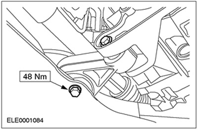
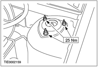
41. Tighten the suspension strut nuts on both sides.
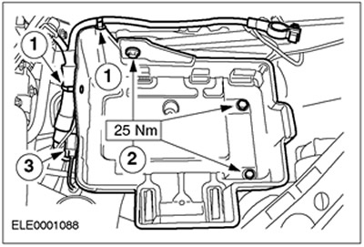
42. Install the battery shelf.
- 1. Connect the wiring harness.
- 2. Tighten the bolts.
- 3. Connect the plug connector and fix it.
43. Bleed the clutch fluid. Refer to Section 308-00 for more information.
44. Adjust shift cables. Refer to Section 308-00 for more information.
45. Install battery. Refer to Section 414-01 for more information.
46. Standard final operations.
- Check fluid levels and correct if necessary.
- Check the wiring of the vacuum hoses and electrical wiring and secure them with clamps.
Visitor comments