Withdrawal
The manual transmission is removed from the bottom of the engine compartment, after disconnecting it from the engine. Due to the fact that the gearbox has a significant weight, it is necessary to use a jack or other lifting mechanism to lower it. Also, when removing the gearbox, it is necessary to support the engine, for which a second jack can be used.
Remove the negative terminal from the battery. Remove the air filter and elements of the air supply system to the engine. Disconnect the clutch cable from the clutch release lever.
Unscrew the lock nut and remove the speedometer cable from the gearbox. Also, if installed, disconnect the vehicle speed sensor connector.
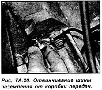
Unscrew the bolt and remove the ground bar from the gearbox.
Remove the transmission ventilation hose from the hole in the side member. To ensure correct adjustment of the gearshift mechanism. when installing the gearbox, engage second gear on a four-speed gearbox or fourth gear on a five-speed gearbox.
Unscrew the top three bolts securing the gearbox to the engine (see fig. 7A.20).
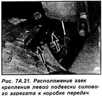
Unscrew the two nuts securing the left suspension of the power unit to the gearbox (see fig. 7A.21).
Raise the front of the car and secure it on stands.
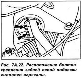
On HCS engines, unscrew and remove the fourth cylinder spark plug. so as not to damage it when lifting the engine with a winch. Place a jack under the engine and raise it just enough to support the weight of the engine on the jack. Unscrew the two bolts and remove the rear left suspension of the power unit (see fig. 7A.22).
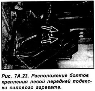
Similarly, unscrew the two bolts securing the front left suspension of the power unit (see fig. 7A.23). Disconnect the connector from the reversing light switch. Disconnect the wires, then unscrew the bolts and remove the starter.
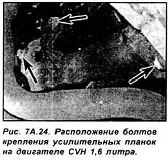
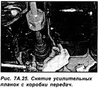
On a 16 liter CVH engine, unscrew the seven bolts securing the reinforcement bars and remove the reinforcement bars on each side. Unscrew the bolt and remove the intermediate plate (see fig. 7A.24, 7A.25).
On 1.3 and 1.4 liter engines, unscrew the bolts and remove the intermediate plate.
Before disengaging the shift rod, mark the position of the shift rod and shift shaft. Unscrew the gearbox stabilizer mounting bolt, disconnect it from the gearbox and, using a wire, tie it to the gearshift rod.
Remove both transverse arms, while first unscrewing the mounting bolt on the bracket, and then the nut on the ball joint. Unscrew and remove the left tie rod ball joint from the steering knuckle. Remove the drive shaft from the gearbox. To do this, insert a crowbar or a large screwdriver between the constant velocity joint and the gearbox housing, and while the assistant pulls the car wheel outward with a strong sharp blow to the end of the crowbar, disengage the drive shaft in the differential side gear. Tie the drive shaft removed from the gearbox to the steering rods with soft wire. Remove the second drive shaft in the same way. Instead of the extracted drive shafts, insert plastic or wooden plugs to fix the differential side gears.
Slightly lower the engine with the gearbox, then unscrew the fastening nut and remove the suspension from the gearbox. Unscrew bolts of fastening of a transmission to the engine. Recheck that all transmission connections are separated.
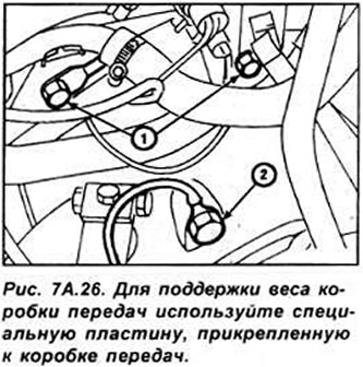
Check that the engine is securely supported. Engine support can be carried out either with a winch or a jack from below the car (see fig. 7A.26).
Raise the gearbox slightly by hand, move it away from the engine until the clutch disc hub splines disengage from the input shaft, then lower and remove the gearbox from under the car.
Installation
Installation is done in sequence. withdrawal, taking into account the following points:
- check that all mating surfaces are clean;
- lubricate the spline of the gearbox input shaft and the release bearing guide bushing with a thin, even layer of special grease, as during clutch operation, excess lubricant will be thrown onto the working surfaces of the clutch;
- on 1.3 and 1.4 liter engines, check that the connection board is properly seated on the drive pins on the engine;
- when installing the drive shafts in the gearbox, use new circlips to fix the drive shafts;
- install the gearbox support holder on 3 studs and tighten with nuts;
- lower the car. Raise the engine with a lifting device. until the threaded holes on the gearbox support line up. Insert 2 bolts and tighten them to the required torque;
- reinstall and secure the transverse arms and the left tie rod joint;
- connect and adjust the gearshift mechanism. Tighten all bolts and nuts to the required torque;
- top up the gear oil level in the gearbox if necessary.
Visitor comments