Special tool
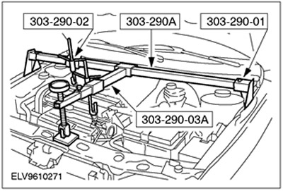
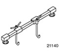 | Engine Support Beam 303-290A (21-140A) |
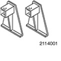 | Adapter for 303-290A (21-140) 303-290-01 (21-140-01) |
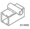 | Adapter for 303-290A (21-140) 303-290-02 (21-140-02) |
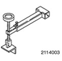 | Adapter for 303-290A (21-140) 303-290-03A (21-140-03A) |
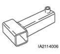 | Adapter for 303-290A (21-140) 303-290-06 (21-140-06) |
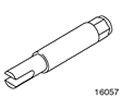 | Drive axle half shaft puller 308-192 (16-057) |
General equipment:
- Gearbox jack
- Technological plugs
- Fixing clamp
All cars
1. General notes:
- Items that apply to specific variants and not to all vehicles are marked with a special note.
- If necessary, cut the clamps and install new ones during installation.
2. Standard preparatory operations:
- Please mark the radio key code.
- Mark the pre-programmed radio stations.
3. Remove the battery. For more information, refer to Section 414-01.
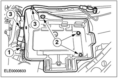
4. Remove the battery tray.
- 1. Release and disconnect the plug connector.
- 2. Remove the bolts.
- 3. Release the wiring harness.
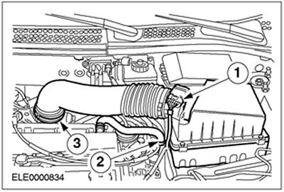
5. Remove the air filter housing.
- 1. Disconnect the mass air flow (MAF) sensor connector.
- 2. Disconnect the crankcase ventilation hose.
- 3. Disconnect the inlet hose.
- Remove the air filter housing from the rubber grommets.
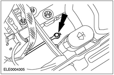
6. Disconnect the ground wire.
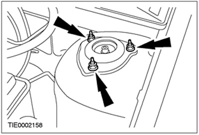
7. Loosen the suspension strut nuts five turns on both sides.
8. Remove the intake manifold.
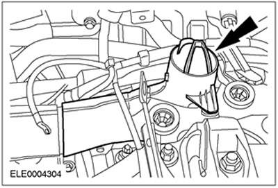
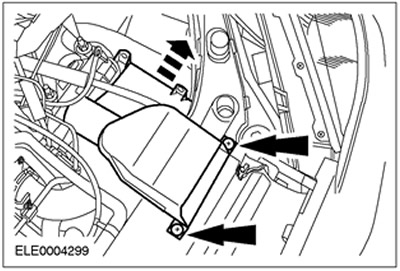
9.
NOTE: The resonator is inserted into the bracket.
Remove the air filter inlet pipe together with the resonator.
10. Raise the vehicle. Refer to Section 100-02 for additional information.
Cars manufactured up to 10.2001.
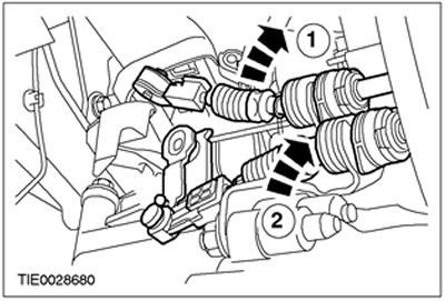
11. Disconnect the gear shift cables from the gear shift lever.
- 1. Disconnect the gear shift cable from the gear shift lever.
- 2. Disconnect the gear selector cable from the gear shift lever.
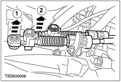
12. Disconnect the gear shift cables from the bracket.
- 1. Release the support bracket by turning it counterclockwise and disconnect the gear shift cable.
- 2. Release the support bracket by turning it counterclockwise and disconnect the gear selector cable.
Cars manufactured since 10.2001
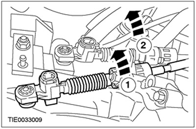
13.
NOTE: Press the shift cable lock buttons.
Disconnect the gear shift cables from the transmission.
- 1. Disconnect the gear shift cable from the gear shift lever.
- 2. Disconnect the gear selector cable from the selector lever.
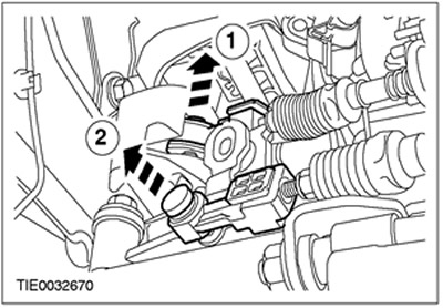
14. Disconnect the gear shift cables from the bracket.
- 1. Release the support bracket by turning it counterclockwise and disconnect the gear shift cable.
- 2. Release the support bracket by turning it counterclockwise and disconnect the gear selector cable.
All cars
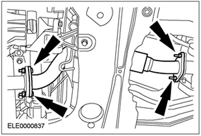
15. Remove the flexible exhaust pipe.
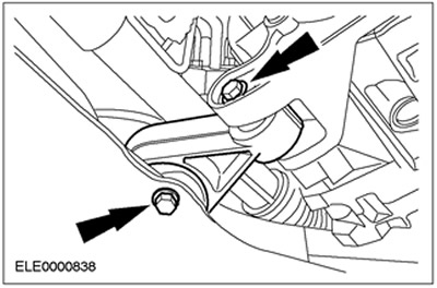
16. Remove the roll limiter.
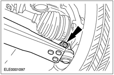
17. Disconnect the lower control arms on both sides. Disconnect the heat shield.
18.
CAUTION: The inner hinge should not be deflected at an angle exceeding 18 degrees, and the outer hinge should not be deflected at an angle exceeding 45 degrees.
NOTE: Discard the bearing cap and nuts as they are no longer needed.
Disconnect the right half shaft of the front drive axle together with the intermediate shaft.
- Remove the intermediate shaft bearing cap.
- Remove the intermediate shaft with the axle shaft from the gearbox and tie them together using clamps.
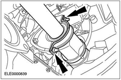
19.
CAUTION: The inner hinge should not be deflected at an angle exceeding 18 degrees, and the outer hinge should not be deflected at an angle exceeding 45 degrees.
NOTE: Discard the snap ring as it is no longer needed.
Disconnect the left half shaft of the front drive axle from the gearbox.
- Disconnect the left half shaft of the front drive axle from the gearbox. Use a special tool.
- Remove the axle shaft from the gearbox and tie it down using cable ties.
- Plug the hole in the gearbox using a service plug.
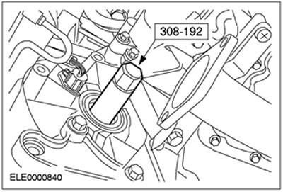
20. Remove the drive belt cover.
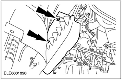
21. Lower the vehicle.
22.
WARNING: Brake fluid leakage. Avoid contact with skin or eyes. If brake fluid comes into contact with skin or eyes, rinse immediately with water.
CAUTION: If brake fluid comes into contact with paintwork, immediately wash the affected areas with water.
Disconnect the high pressure line from the clutch slave cylinder.
- Remove the clamp.
- Pull out the high pressure line and tie it up.
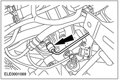
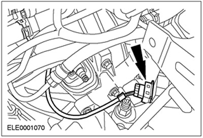
23. Disconnect the reversing light switch connector.
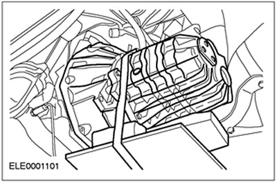
24. Install the special tools (the picture shows the battery installed).
25. Disconnect the rear engine mount.
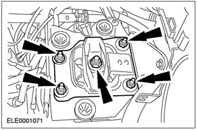
26. Slightly lower the engine and gearbox assembly using special tool 303-290A.
27. Remove the rear engine mount bracket.
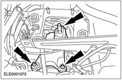
28. Remove the two upper flange bolts.
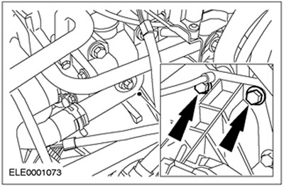
29.
NOTE: Do not disconnect the electrical wiring from the starter.
Disconnect the starter.
- Remove three bolts (two bolts shown).
- Tie up the starter.
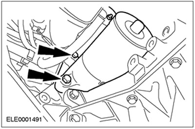
30. Raise the vehicle. Refer to Section 100-02 for additional information.
31. Disconnect the vehicle speed sensor (VSS) connector.
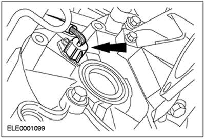
32. Move the engine and gearbox assembly forward and insert a 350 mm long wooden block between the engine and the subframe.
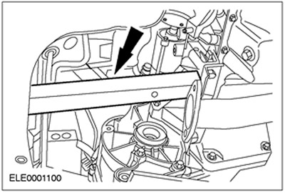
33. Place a transmission jack under the transmission and secure the transmission using wooden blocks and a locking clamp.
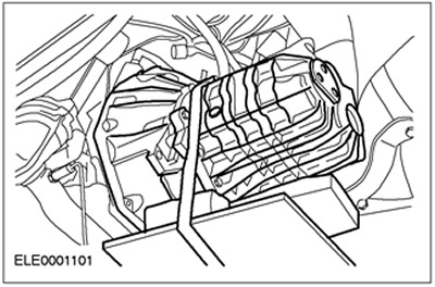
34. Remove the lower flange bolts (five bolts).
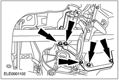
35. Remove the upper flange bolts (four bolts).
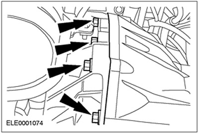
36. Disconnect the gearbox from the engine and lower it using a gearbox jack.