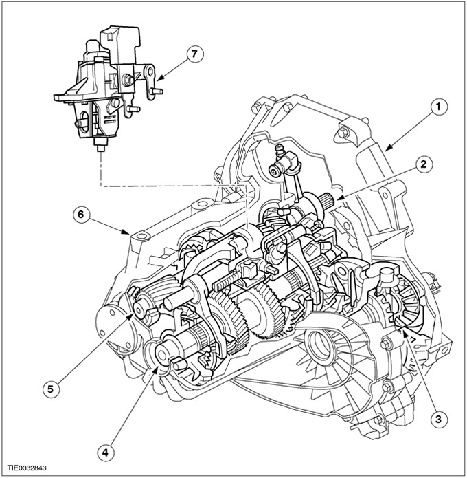
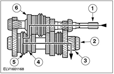
| Pos. | Spare Part No | Name |
| 1 | - | Transmission housing, clutch side |
| 2 | - | clutch slave cylinder |
| 3 | - | Differential |
| 4 | - | output shaft |
| 5 | - | input shaft |
| 6 | - | Transmission housing in a block with a drive axle |
| 7 | - | Gear selector |
MTX-75 Drive Axle Transmission - Vehicles built from 01.2000
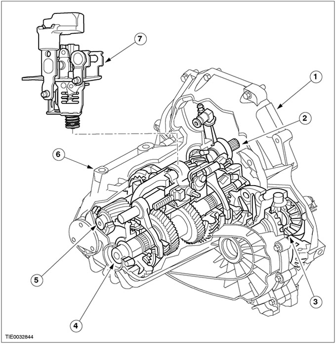
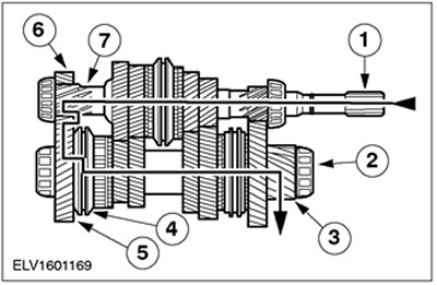
| Pos. | Spare Part No | Name |
| 1 | - | Transmission housing, clutch side |
| 2 | - | clutch slave cylinder |
| 3 | - | Differential |
| 4 | - | output shaft |
| 5 | - | input shaft |
| 6 | - | Transmission housing in a block with a drive axle |
| 7 | - | Gear selector |
Transaxle Transmission MTX-75 - Vehicles built from 10.2001
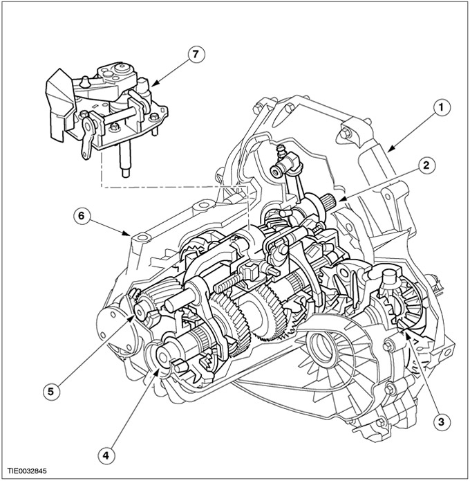
| Pos. | Spare Part No | Name |
| 1 | - | Transmission housing, clutch side |
| 2 | - | clutch slave cylinder |
| 3 | - | Differential |
| 4 | - | output shaft |
| 5 | - | input shaft |
| 6 | - | Crankcase of the gearbox in the block with the driving axle - from the side of the gearbox in the block with the driving axle |
| 7 | - | External gear change mechanism. |
The MTX75 manual gearbox is the so-called «two-shaft» gearbox in a block with a driving axle
MTX-75 means:
- M - Mechanical
- T - Gearbox
- X - Transmission in a block with a driving axle (front wheel drive)
- 75 - Distance between primary and secondary shafts in mm.
The aluminum gearbox housing in the block with the drive axle consists of two sealed sections. To reduce the level of noise and vibrations, additional fins have been introduced into the crankcase design, which increases the rigidity of the structure.
Gears in all gears «twin-shaft» gearboxes are in constant engagement. In each gear, the required gear ratio is provided by a pair of gears.
When reverse gear is selected, the counter gear changes the direction of rotation of the output shaft.
The primary and secondary shafts are mounted on roller bearings. To further improve the stability and quality of gear shifting, the design of the gear selector has been modified. It has a built-in maintenance-free («maintenance-free») cable working mechanism.
All gears, including the reverse gear, are synchronized helical gears running on needle roller bearings.
First, second and third gears (vehicles manufactured up to 08.2000) have dual sync.
Primary and secondary shafts
General view of the primary and secondary shafts
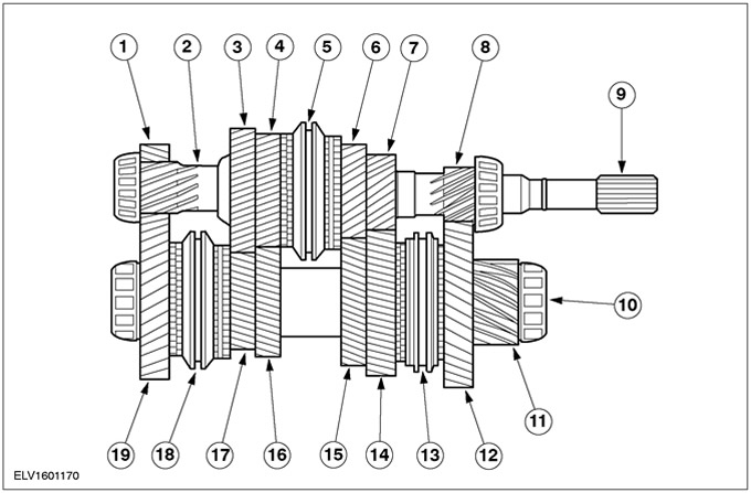
| Pos. | Spare Part No | Name |
| 1 | - | Reverse intermediate gear |
| 2 | - | Reverse gear |
| 3 | - | 5th gear |
| 4 | - | 4th gear |
| 5 | - | Third and fourth gear synchronizer |
| 6 | - | Third gear |
| 7 | - | Second gear |
| 8 | - | First gear |
| 9 | - | input shaft |
| 10 | - | output shaft |
| 11 | - | Output shaft drive gear |
| 12 | - | First gear |
| 13 | - | 1st and 2nd gear synchronizer |
| 14 | - | Second gear |
| 15 | - | Third gear |
| 16 | - | 4th gear |
| 17 | - | 5th gear |
| 18 | - | Synchronizer for fifth gear and reverse gear |
| 19 | - | Reverse gear |
In the neutral position, none of the gears is connected to the input or output shaft through the corresponding synchronizer. Torque is not transmitted to the differential.
The input and output shafts are mounted on two roller bearings: one of which is located in the gearbox housing section in the drive axle block on the clutch side, and the other is located in the gearbox housing section in the drive axle block on the gearbox side of the drive axle block.
The output shaft drive gear is in constant mesh with the differential drive ring gear.
The third and fourth gears and the third and fourth gear synchronizer are located on the input shaft. The gear rims of the gears of the first, second and reverse gears are an integral part of the input shaft.
The first, second, fifth and reverse gears and the first and second gear synchronizer and the fifth and reverse gear synchronizer are located on the output shaft. On vehicles manufactured up to 07.2000, the gear rims of the third and fourth gears are an integral part of the output shaft.
Differential
The main elements of the differential:
- output gear;
- Cylindrical gear;
- four gears (differential pinions and side gears), located at right angles to each other;
- Differential housing with two roller bearings
The gearbox in a block with a driving axle is installed in a two-section aluminum crankcase, which is flange-mounted to the engine.
The axle shafts have knurled teeth and are fixed with retaining rings. The torque is transmitted from the spur gear to the axle shafts with the help of two satellites mounted on the axle and two side gears.
When cornering, the side gears must rotate at different speeds, because wheels travel different distances. This is achieved by differential pinion gears that rotate on their own axis and mesh with side gears that rotate at different speeds.
First gear
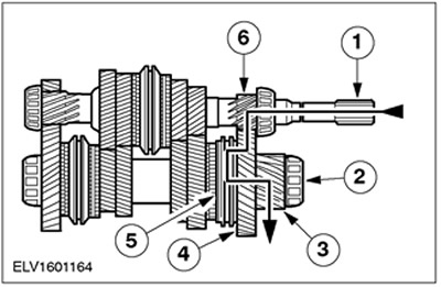
| Pos. | Spare Part No | Name |
| 1 | - | input shaft |
| 2 | - | output shaft |
| 3 | - | Output shaft drive gear |
| 4 | - | First gear |
| 5 | - | Synchronizer of the first and second gears |
| 6 | - | First gear |
Second gear
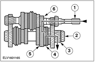
| Pos. | Spare Part No | Name |
| 1 | - | input shaft |
| 2 | - | output shaft |
| 3 | - | Output shaft drive gear |
| 4 | - | Synchronizer of the first and second gears |
| 5 | - | Second gear |
| 6 | - | Second gear |
Third gear
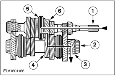
| Pos. | Spare Part No | Name |
| 1 | - | input shaft |
| 2 | - | output shaft |
| 3 | - | Output shaft drive gear |
| 4 | - | Third gear |
| 5 | - | 3rd and 4th gear synchronizer |
| 6 | - | Third gear |
Fourth gear
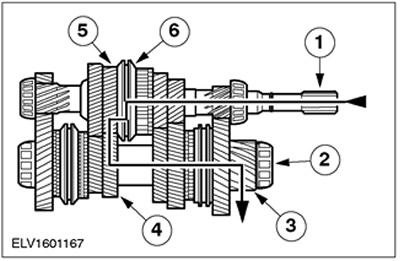
| Pos. | Spare Part No | Name |
| 1 | - | input shaft |
| 2 | - | output shaft |
| 3 | - | Output shaft drive gear |
| 4 | - | 4th gear |
| 5 | - | 4th gear |
| 6 | - | Third and fourth gear synchronizer |
Fifth gear
| Pos. | Spare Part No | Name |
| 1 | - | input shaft |
| 2 | - | output shaft |
| 3 | - | Output shaft drive gear |
| 4 | - | 5th gear |
| 5 | - | Synchronizer for fifth gear and reverse gear |
| 6 | - | 5th gear |
Reverse gear
| Pos. | Spare Part No | Name |
| 1 | - | input shaft |
| 2 | - | output shaft |
| 3 | - | Output shaft drive gear |
| 4 | - | Synchronizer for fifth gear and reverse gear |
| 5 | - | Reverse gear |
| 6 | - | Reverse intermediate gear |
| 7 | - | Reverse gear |
Reverse intermediate gear
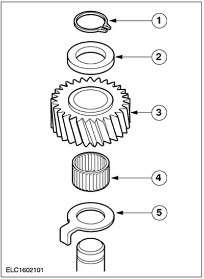
| Pos. | Spare Part No | Name |
| 1 | - | Retaining ring |
| 2 | - | Upper thrust washer |
| 3 | - | Reverse intermediate gear |
| 4 | - | Needle roller bearing |
| 5 | - | Bottom thrust washer |
The reverse gear is driven by the input shaft. Its purpose is to change the direction of rotation of the secondary shaft with the selected reverse gear.
The reverse idle gear is located on the idle gear shaft and is mounted on a needle bearing.
Gear select lock mechanism
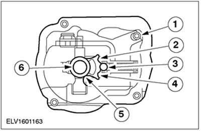
| Pos. | Spare Part No | Name |
| 1 | - | gear selector housing |
| 2 | - | Position of the selector finger for 1st, 3rd and 5th gears |
| 3 | - | Intermediate position of the gear selector finger |
| 4 | - | 2nd, 4th and reverse gear selection pin position |
| 5 | - | Gear selector |
| 6 | - | Shaft of a choice of transfers |
The gear select lock mechanism and gear select pin are mounted on a bushing in the gear select housing and use a spring loaded ball to hold the selected gear in engagement until another gear is selected.
The gear selector lock mechanism has three positions. The reversing light switch is located on the side of the gear selector housing.
Input shaft - Vehicles built up to 08.2001
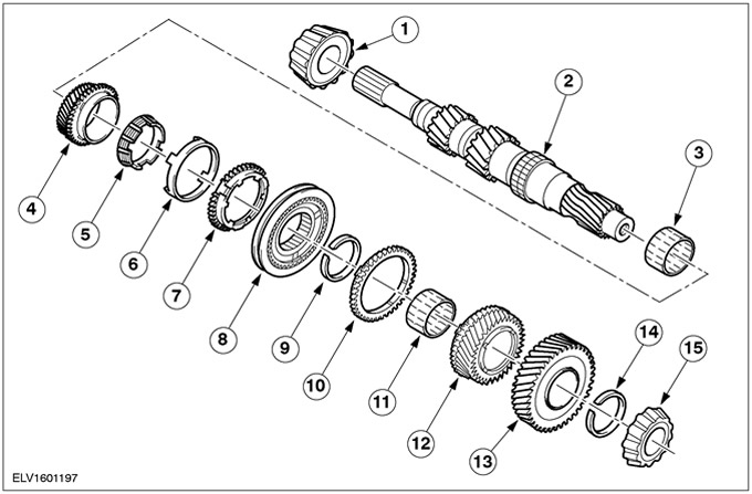
| Pos. | Spare Part No | Name |
| 1 | - | Roller bearing |
| 2 | - | input shaft |
| 3 | - | Needle bearing for third gear |
| 4 | - | Third gear |
| 5 | - | 3rd gear inner synchronizer ring |
| 6 | - | 3rd gear synchronizer conical ring |
| 7 | - | 3rd gear synchronizer outer ring |
| 8 | - | The synchronizer of the third and fourth gears assy |
| 9 | - | Retaining ring |
| 10 | - | 4th gear synchronizer ring |
| 11 | - | 4th gear needle roller bearing |
| 12 | - | 4th gear |
| 13 | - | 5th gear |
| 14 | - | Retaining ring |
| 15 | - | Roller bearing |
Input shaft - Vehicles manufactured from 08.2001
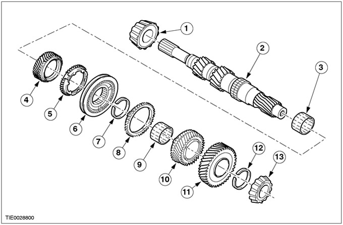
| Pos. | Spare Part No | Name |
| 1 | - | Roller bearing |
| 2 | - | input shaft |
| 3 | - | Third gear needle bearing |
| 4 | - | Third gear |
| 5 | - | Third gear synchronizer ring |
| 6 | - | The synchronizer of the third and fourth gears assy |
| 7 | - | Retaining ring |
| 8 | - | 4th gear synchronizer ring |
| 9 | - | 4th gear needle roller bearing |
| 10 | - | 4th gear |
| 11 | - | 5th gear |
| 12 | - | Retaining ring |
| 13 | - | Roller bearing |
Third, fourth, fifth and reverse gears located on the output shaft - Vehicles manufactured up to 07.2000
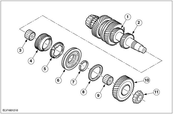
| Pos. | Spare Part No | Name |
| 1 | - | Third gear |
| 2 | - | 4th gear |
| 3 | - | Needle roller bearing |
| 4 | - | 5th gear |
| 5 | - | 5th gear synchronizer ring |
| 6 | - | Fifth gear and reverse gear synchronizer assembly |
| 7 | - | Retaining ring |
| 8 | - | Reverse synchronizer ring |
| 9 | - | Needle roller bearing |
| 10 | - | Reverse gear |
| 11 | - | Roller bearing |
1st and 2nd gears located on the output shaft - Vehicles manufactured up to 07.2000
| Pos. | Spare Part No | Name |
| 1 | - | output shaft |
| 2 | - | Needle roller bearing |
| 3 | - | Second gear |
| 4 | - | Synchronizer inner ring |
| 5 | - | Tapered synchronizer ring |
| 6 | - | Synchronizer outer ring |
| 7 | - | The synchronizer of the first and second transfers assy |
| 8 | - | Retaining ring |
| 9 | - | Synchronizer outer ring |
| 10 | - | Tapered synchronizer ring |
| 11 | - | Synchronizer inner ring |
| 12 | - | Needle roller bearing |
| 13 | - | First gear |
| 14 | - | Output shaft drive gear |
| 15 | - | Retaining ring |
| 16 | - | Roller bearing |
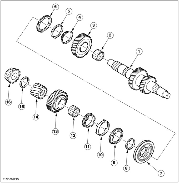
Output shaft - Vehicles manufactured from 08.2000
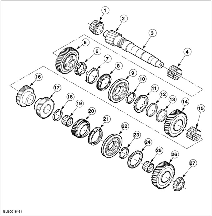
| Pos. | Spare Part No | Name |
| 1 | - | Roller bearing |
| 2 | - | Output shaft drive gear |
| 3 | - | output shaft |
| 4 | - | First gear needle roller bearing |
| 5 | - | First gear |
| 6 | - | 1st gear inner synchronizer ring |
| 7 | - | Tapered synchronizer ring first gear |
| 8 | - | 1st gear synchronizer outer ring |
| 9 | - | The synchronizer of the first and second transfers assy |
| 10 | - | Retaining ring |
| 11 | - | 2nd gear synchronizer ring |
| 12 | - | Second gear conical synchronizer ring |
| 13 | - | 2nd gear inner synchronizer ring |
| 14 | - | Second gear |
| 15 | - | Second gear needle roller bearing |
| 16 | - | Third gear |
| 17 | - | 4th gear |
| 18 | - | Retaining ring |
| 19 | - | 5th gear needle roller bearing |
| 20 | - | 5th gear |
| 21 | - | 5th gear synchronizer ring |
| 22 | - | Fifth gear and reverse gear synchronizer assembly |
| 23 | - | Retaining ring |
| 24 | - | Reverse synchronizer ring |
| 25 | - | Reverse Needle Roller Bearing |
| 26 | - | Reverse gear |
| 27 | - | Roller bearing |
Gear selector - Vehicles built up to 01.2000
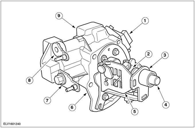
| Pos. | Spare Part No | Name |
| 1 | - | Reversing light switch |
| 2 | - | Gear selector |
| 3 | - | Bracket for selector pin |
| 4 | - | Shaft of a choice of transfers |
| 5 | - | Gear selector |
| 6 | - | gear selector housing |
| 7 | - | Selection lever |
| 8 | - | shift lever |
| 9 | - | gear selector cover |
Gear selector housing - Vehicles built up to 01.2000
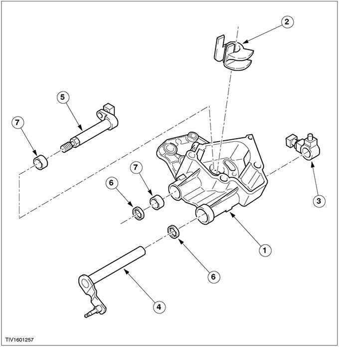
| Pos. | Spare Part No | Name |
| 1 | - | gear selector housing |
| 2 | - | Shift and Select Lever Shaft Guide Bracket |
| 3 | - | gear selector |
| 4 | - | Select lever and select lever shaft |
| 5 | - | Shift lever shaft |
| 6 | - | Oil seal |
| 7 | - | Needle roller bearing |
Gear selection gate - Vehicles built up to 01.2000
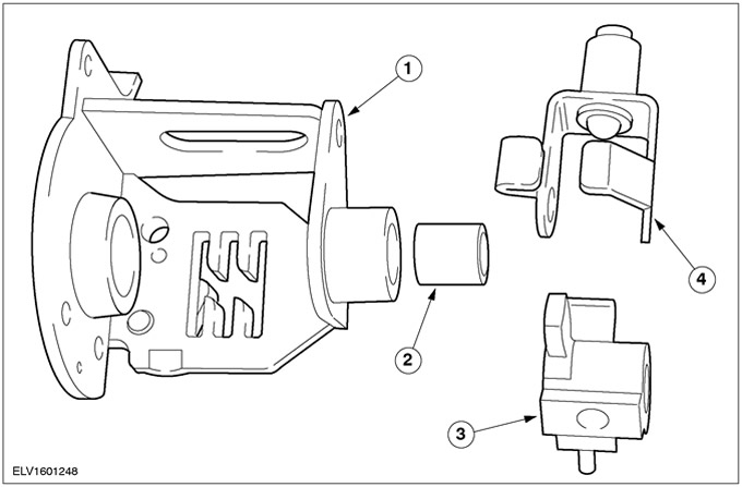
| Pos. | Spare Part No | Name |
| 1 | - | Gear selector |
| 2 | - | Select shaft ball bushing |
| 3 | - | Gear selector |
| 4 | - | Selector pin bracket and shift lock ball |
Visitor comments