|
STATES |
DETAILS/RESULTS/ACTIONS |
|
A1: FUEL GAUGE TEST |
|
|
1 Activate instrument cluster self-test number one, pointer sweep. |
|
|
• Does the fuel gauge needle go through full sweep? |
|
|
→ Yes |
|
|
Go to A2 |
|
|
→ No |
|
|
INSTALL a new instrument panel. For more information, refer to Instrument panel available in this section. CHECK the system is working properly. |
|
|
A2: ENSURE FUEL GAUGE FAULT |
|
|
1 Drive the ON position. |
|
|
• The fuel gauge shows the level below the position «empty tank» (default position)? |
|
|
→ Yes |
|
|
Go to A3 |
|
|
→ No |
|
|
Go to A7 |
|
|
A3: CHECK FOR CURRENT FAULT |
|
|
1 Activate instrument cluster self-test number 10, fuel volume input test. |
|
|
• Is the output value equal to or less than F010? |
|
|
→ Yes |
|
|
There is a short circuit on «mass» - Vehicles with a non-adaptive fuel system. Go to A17 |
|
|
There is a short circuit on «mass» - cars with adaptive fuel system. Go to A4 |
|
|
→ No |
|
|
If the output value is between F011 and F254, there is a valid input signal. Go to A7 |
|
|
If the output value is F255, there is an open circuit or a short to battery voltage - vehicles with a non-adaptive fuel system. Go to A13 |
|
|
If the output value is F255, there is an open circuit or a short to battery voltage - vehicles with adaptive fuel system. Go to A8 |
|
|
A4: CHECK FOR SHORT CIRCUIT TO « MASS » FUEL TANK SENSOR ELECTRICAL CIRCUIT |
|
|
1 Disconnect the C732 fuel pump module. |
|
|
• Does the fuel input value change to F255? |
|
|
→ Yes |
|
|
Install a new fuel pump module. See Section 310-01 for more information. CHECK the system is working properly. |
|
|
→ No |
|
|
Go to A5 |
|
|
A5: CHECK FOR SHORT CIRCUIT ON « MASS » ADAPTIVE FUEL MODULE ELECTRICAL CIRCUIT |
|
|
1 Disconnect the C21 adaptive fuel module. |
|
|
• Does the fuel input value change to F255? |
|
|
→ Yes |
|
|
INSTALL a new adaptive fuel module. CHECK the system is working properly. |
|
|
→ No |
|
|
Go to A6 |
|
|
A6: 8-GA7 ELECTRICAL CIRCUIT CHECK (WHITE-RED) FOR A BREAK |
|

|
1 Disconnect the C809 instrument panel. |
|
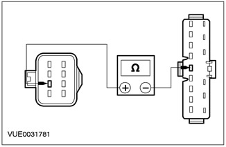
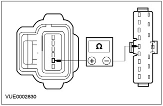
2 Measure the resistance between pin 8 C809 of the instrument panel, circuit 8-GA7 (white-red), from the wiring side, and «weight». |
|
|
• Is the resistance less than 5 ohms? |
|
|
→ Yes |
|
|
REPAIR the electrical circuit. CHECK the system is working properly. |
|
|
→ No |
|
|
INSTALL a new instrument panel. For more information, refer to Instrument panel available in this section. CHECK the system is working properly. |
|
|
A7: RECOVERING STORED DTCs |
|
|
1 Connect the C732 fuel pump module. |
|
|
2 Activate instrument cluster self-test number 6, list of stored DTCs. |
|
|
• Are any DTCs stored in memory? |
|
|
→ Yes |
|
|
REFER to instrument panel DTC list. |
|
|
→ No |
|
|
Install a new fuel pump module. See Section 310-01 for more information. CHECK the system is working properly. |
|
|
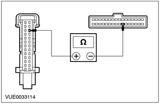
A8: INSPECT CIRCUIT 8-GA7 (WHITE-RED) FOR A BREAK |
|
|
1 Enter the OFF position. |
|
|
2 Disconnect the C809 instrument panel. |
|
|
3 Disconnect C61/C63. |
|

|
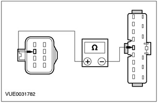
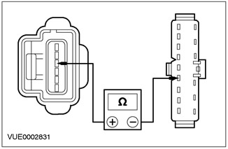
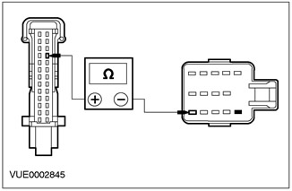
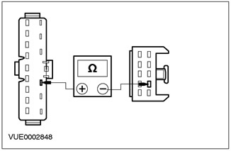
4 Measure the resistance between pin 8 C809 of the instrument panel, circuit 8-GA7 (white-red), from the wiring side, and pin 11 C63, electrical circuit 8-GA7 (white-red), from the side of the electrical wiring. |
|
• Is the resistance less than 5 ohms? |
|
|
→ Yes |
|
|
Go to A9 |
|
|
→ No |
|
|
Repair the electrical circuit. Check the correct operation of the system. |
|
|
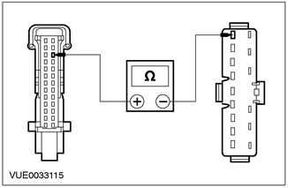
A9: 8-GA7 ELECTRICAL CIRCUIT CHECK (WHITE-RED) FOR A BREAK |
|
|
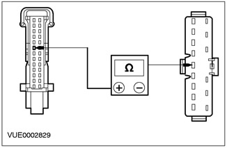
1 Measure the resistance between pin 2 C21 of the adaptive fuel module circuit 8-GA7 (white-red), from the wiring side, and pin 21 C61, electrical circuit 8-GA7 (white-red), from the side of the electrical wiring. |
|
• Is the resistance less than 5 ohms? |
|
|
→ Yes |
|
|
Go to A10 |
|
|
→ No |
|
|
REPAIR the electrical circuit. CHECK the system is working properly. |
|
|
A10: 9-GA7 ELECTRICAL CIRCUIT CHECK (BROWN-RED) FOR A BREAK |
|
|
1 Measure the resistance between pin 3 C21 of the adaptive fuel module circuit 9-GA7 (brown red), from the wiring side, and pin 20 C61, electrical circuit 9-GA7 (brown red), from the side of the electrical wiring. |
|
• Is the resistance less than 5 ohms? |
|
|
→ Yes |
|
|
Go to A11 |
|
|
→ No |
|
|
REPAIR Circuit 9-GA7 (brown red). CHECK the system is working properly. |
|
|
A11: 9-GA7 ELECTRICAL CIRCUIT CHECK (BROWN-RED) FOR A BREAK |
|

|
1 Measure the resistance between pin 15 C809 of the instrument panel, circuit 9-GA7 (brown red), from the wiring side, and pin 10 C63, electrical circuit 9-GA7 (brown red), from the side of the electrical wiring. |
|
• Is the resistance less than 5 ohms? |
|
|
→ Yes |
|
|
Go to A12 |
|
|
→ No |
|
|
Repair the electrical circuit. Check the correct operation of the system. |
|
|
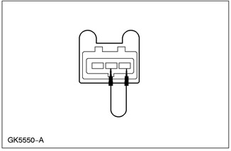
A12: FUEL TANK SENSOR OPEN CHECK |
|
|
1 Disconnect the C732 fuel pump module. |
|
|
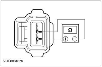
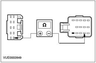
2 Measure the resistance between C372 pin 2 of the fuel pump module circuit 8-GA7 (white-red), wiring side, and pin 4 C372 of the fuel pump module, circuit 9-GA7 (brown red), from the side of the electrical wiring. |
|
• Is the resistance greater than 150 ohms? |
|
|
→ Yes |
|
|
INSTALL a new fuel pump module. See Section 310-01 for more information. CHECK the system is working properly. |
|
|
→ No |
|
|
INSTALL a new adaptive fuel module. Check the correct operation of the system. |
|
|
A13: 8-GA7 ELECTRICAL CIRCUIT CHECK (WHITE-RED) FOR A BREAK |
|
|
1 Enter the OFF position. |
|
|
2 Disconnect the C809 instrument panel. |
|
|
3 Disconnect C61/C63. |
|
|
4 Measure the resistance between pin 8 C809 of the instrument panel, circuit 8-GA7 (white-red), from the wiring side, and pin 11 C63, electrical circuit 8-GA7 (white-red), from the side of the electrical wiring. |
|
• Is the resistance less than 5 ohms? |
|
|
→ Yes |
|
|
Go to A14 |
|
|
→ No |
|
|
REPAIR the electrical circuit. CHECK the system is working properly. |
|
|
A14: 8-GA7 ELECTRICAL CIRCUIT CHECK (WHITE-RED) FOR A BREAK |
|
|
1 Disconnect the C732 fuel pump module. |
|
|
2 Measure the resistance between C732 pin 2 of the fuel pump module circuit 8-GA7 (white-red), from the wiring side, and pin 21 C61, electrical circuit 8-GA7 (white-red), from the side of the electrical wiring. |
|
• Is the resistance less than 5 ohms? |
|
|
→ Yes |
|
|
Go to A15 |
|
|
→ No |
|
|
Repair the electrical circuit. Check the correct operation of the system. |
|
|
A15: 9-GA7 ELECTRICAL CIRCUIT CHECK (BROWN-RED) FOR A BREAK |
|
|
1 Measure the resistance between C732 pin 4 of the fuel pump module circuit 9-GA7 (brown red), from the wiring side, and pin 20 C61, electrical circuit 9-GA7 (brown red), from the side of the electrical wiring. |
|
• Is the resistance less than 5 ohms? |
|
|
→ Yes |
|
|
Go to A16 |
|
|
→ No |
|
|
REPAIR the electrical circuit. CHECK the system is working properly. |
|
|
A16: 9-GA7 ELECTRICAL CIRCUIT CHECK (BROWN-RED) FOR A BREAK |
|

|
1 Measure the resistance between pin 15 C809 of the instrument panel, circuit 9-GA7 (brown red), from the wiring side, and pin 10 C63, electrical circuit 9-GA7 (brown red), from the side of the electrical wiring. |
|
• Is the resistance less than 5 ohms? |
|
|
→ Yes |
|
|
INSTALL a new fuel pump module. See Section 310-01 for more information. CHECK the system is working properly. |
|
|
→ No |
|
|
Repair the electrical circuit. Check the correct operation of the system. |
|
|
A17: CHECK FOR SHORT CIRCUIT ON «MASS» FUEL TANK SENSOR ELECTRICAL CIRCUIT |
|
|
1 Disconnect the C732 fuel pump module. |
|
|
• Does the fuel input value change to F255? |
|
|
→ Yes |
|
|
INSTALL a new fuel pump module. See Section 310-01 for more information. CHECK the system is working properly. |
|
|
→ No |
|
|
Go to A18 |
|
|
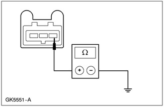
A18: 8-GA7 ELECTRICAL CIRCUIT CHECK (WHITE-RED) FOR A BREAK |
|
|
1 Disconnect the instrument panel C809. |
|
|
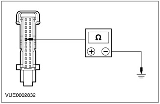
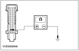
2 Measure the resistance between pin 8 C809 of the instrument panel, circuit 8-GA7 (white-red), from the wiring side, and «weight». |
|
• Is the resistance less than 5 ohms? |
|
|
→ Yes |
|
|
REPAIR the electrical circuit. CHECK the system is working properly. |
|
|
→ No |
|
|
INSTALL a new instrument panel. For more information, refer to Instrument panel available in this section. CHECK the system is working properly. |
|
PINPOINT TEST B: SPEEDOMETER DOES NOT WORK
|
STATES |
DETAILS/RESULTS/ACTIONS |
|
B1: CHECKING THE FUNCTION OF THE SPEEDOMETER |
|
|
1 Activate instrument cluster self-test number one, pointer sweep. |
|
|
• Is the speedometer needle sweeping? |
|
|
→ Yes |
|
|
Navigate to B2 |
|
|
→ No |
|
|
INSTALL a new instrument panel. For more information, refer to Instrument panel available in this section. CHECK the system is working properly. |
|
|
B2: RECOVERY OF ANY STORED DTCs |
|
|
1 Activate instrument panel self-test number 6, list of stored DTCs. |
|
|
• Are any DTCs stored in memory? |
|
|
→ Yes |
|
|
REFER to instrument panel DTC list. |
|
|
→ No |
|
|
Go to B3 |
|
|
B3: VEHICLE SPEED SENSOR OUTPUT TEST (VSS) |
|
|
1 Activate instrument cluster self-test number 7 (miles per hour) or number 8 (km/h), vehicle speed input. - Vehicle speed input monitoring requires the vehicle to be moving during this test. |
|
|
• Does the speed signal change with speed? |
|
|
→ Yes |
|
|
Go to N1 |
|
|
→ No |
|
|
REFER to WDS for PCM and SCP channel diagnostics. Additional DIAGNOSIS of the VSS sensor is required. See Section 303-14 for more information. |
|
PINPOINT TEST C: INCORRECT TEMPERATURE GAUGE
|
STATES |
DETAILS/RESULTS/ACTIONS |
|
C1: CHECKING THE FUNCTION OF THE TEMPERATURE GAUGE |
|
|
1 Activate instrument cluster self-test number one, pointer sweep. |
|
|
• Does the temperature gauge needle go through full sweep? |
|
|
→ Yes |
|
|
Go to C2 |
|
|
→ No |
|
|
INSTALL a new instrument panel. For more information, refer to Instrument panel available in this section. CHECK the system is working properly. |
|
|
C2: RECOVERY OF ANY STORED DTCs |
|
|
1 Activate instrument cluster self-test number 6, retrieve stored DTCs. |
|
|
• Are there any DTCs stored in the memory? |
|
|
→ Yes |
|
|
REFER to instrument panel DTC list. |
|
|
→ No |
|
|
Go to C3 |
|
|
C3: CYLINDER HEAD TEMPERATURE SENSOR CHECK (CHT) |
|
|
1 Activate instrument cluster self-test number 11, engine temperature input. - Check the input signal when the engine is cold and when the engine is warm. |
|
|
• Is there an input signal from the engine temperature sensor? |
|
|
→ Yes |
|
|
Go to N1 |
|
|
→ No |
|
|
Refer to WDS for PCM and SCP channel diagnostics. Additional DIAGNOSIS of the temperature sensor is required. |
|
PINPOINT TEST D: TACHO DOES NOT WORK
|
STATES |
DETAILS/RESULTS/ACTIONS |
|
D1: TACHOMETER FUNCTION CHECK |
|
|
1 Activate instrument cluster self-test number one, pointer sweep. |
|
|
• Does the tachometer needle go through full sweep? |
|
|
→ Yes |
|
|
Go to D2 |
|
|
→ No |
|
|
INSTALL a new instrument panel. For more information, refer to Instrument panel available in this section. CHECK the system is working properly. |
|
|
D2: RECOVERY OF ANY STORED DTCs |
|
|
1 Activate instrument panel self-test number 6, list of stored DTCs. |
|
|
• Are there any DTCs stored in the memory? |
|
|
→ Yes |
|
|
Refer to the list of instrument panel DTCs. |
|
|
→ No |
|
|
Go to D3 |
|
|
D3: TACH INPUT CHECK |
|
|
1 Activate instrument cluster self-test number 9, tachometer input test (RPM). |
|
|
• Is there an RPM input present? |
|
|
→ Yes |
|
|
Go to N1 |
|
|
→ No |
|
|
Refer to WDS for PCM and SCP channel diagnostics. Additional tachometer DIAGNOSIS required |
|
PINPOINT TEST E: HIGH BEAM INDICATOR LAMP DOES NOT WORK
|
STATES |
DETAILS/RESULTS/ACTIONS |
|
E1: 15S-LE11 ELECTRICAL VOLTAGE TEST (GREEN-WHITE) |
|
|
1 Enter the OFF position. |
|
|
2 Disconnect the C809 instrument panel. |
|
|
3 Drive the ON position. |
|
|
4 Turn the headlight switch to «DOWN LIGHT». |
|
|
5 Set the multifunction switch to «HIGH LIGHT». |
|
|
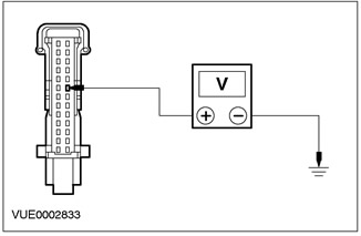
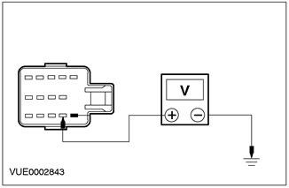
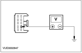
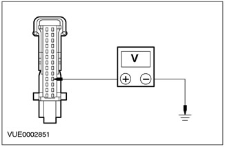
6 Measure voltage between pin 21 C809 of instrument panel, circuit 15S-LE11 (green-white), from the wiring side, and «weight». |
|
• Is the voltage greater than 10 V? |
|
|
→ Yes |
|
|
Go to E2 |
|
|
→ No |
|
|
REPAIR the electrical circuit. CHECK the system is working properly. |
|
|
E2: 91-GG14 ELECTRICAL CIRCUIT CHECK (BLACK AND ORANGE) FOR A SHORT TO THE HIGH BEAM PILOT |
|

|
1 Measure the resistance between pin 2 C809 of the instrument panel, circuit 91-GG14 (black-orange), from the wiring side, and «weight». |
|
• Is the resistance always less than 5 ohms? |
|
|
→ Yes |
|
|
INSTALL a new high beam indicator bulb. For more information, refer to Instrument panel available in this section. CHECK the system is working properly. |
|
|
→ No |
|
|
REPAIR the electrical circuit. Check the correct operation of the system. |
|
PINPOINT TEST F: DOOR LOCK WARNING LIGHT DOES NOT WORK / IS ON PERMANENTLY
|
STATES |
DETAILS/RESULTS/ACTIONS |
|
F1: ELECTRICAL CIRCUIT CHECK 31S-AA17 (BLACK-BLUE) FOR A BREAK |
|
|
1 Enter the OFF position. |
|
|
2 Disconnect C15 CJB. |
|
|
3 Disconnect the C809 instrument panel. |
|
|
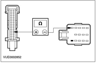
4 Measure the resistance between pin 24 of instrument cluster connector C809, circuit 31S-AA17 (black and blue), and pin 15 of C15 CJB connector, circuit 31S-AA17 (black and blue). |
|
• Is the resistance less than 5 ohms? |
|
|
→ Yes |
|
|
Go to F2 |
|
|
→ No |
|
|
REPAIR the electrical circuit. Check the correct operation of the system. |
|
|
F2: CHECK CJB FOR A BREAK |
|
|
1 Connect C15 CJB. |
|
|
2 Disconnect the C1000 CTM. |
|
|
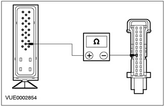
3 Measure the resistance between pin 24 of instrument cluster connector C809, circuit 31S-AA17 (black and blue), and pin 23 of the C1000 CTM connector, on the CJB side. |
|
• Is the resistance less than 5 ohms? |
|
|
→ Yes |
|
|
The fault is in the door lock. See Section 501-14 for more information. |
|
|
→ No |
|
|
Install a new CJB. Check the correct operation of the system. |
|
PINPOINT TEST G: OIL LIGHT DOES NOT WORK
|
STATES |
DETAILS/RESULTS/ACTIONS |
|
G1: CHECKING THE OPERATION OF THE OIL LIGHT |
|
|
1 Drive the ON position. |
|
|
• Is the low fuel warning light on? |
|
|
→ Yes |
|
|
CHECK the condition of the bulb. For more information, refer to Instrument panel available in this section. If the bulb is OK, INSTALL a new instrument cluster. Check the correct operation of the system. |
|
|
→ No |
|
|
Go to G2 |
|
|
G2: ELECTRICAL CIRCUIT CHECK 31S-GC20 (BLACK AND ORANGE) FOR A BREAK |
|
|
1 Detach C953 (1.4/1.6) or C954 (1.8/2.0) oil pressure switch. |
|
|
2 Drive the ON position. |
|
|
3 Connect connector C953 (1.4L/1.6L) or C954 (1.8L/2.0L) With «weight». |
|
|
• Is the oil pressure warning light on? |
|
|
→ Yes |
|
|
INSTALL a new oil pressure switch. Check the correct operation of the system. |
|
|
→ No |
|
|
Repair the electrical circuit. Check the correct operation of the system. |
|
PINPOINT TEST H: BRAKE WARNING LIGHT DOES NOT WORK
|
STATES |
DETAILS/RESULTS/ACTIONS |
|
H1: CHECKING THE OPERATION OF THE BRAKE LAMP |
|
|
1 Activate instrument cluster self-test number 3, warning lights on. |
|
|
• Is the brake system warning light on? |
|
|
→ Yes |
|
|
Go to H2 |
|
|
→ No |
|
|
INSTALL a new bulb. For more information, refer to Instrument panel available in this section. CHECK the system is working properly. |
|
|
H2: 31S-GC6 BRAKE FLUID LEVEL SWITCH CIRCUIT CHECK (BLACK YELLOW) |
|
|
1 Enter the OFF position. |
|
|
2 Disconnect the C810 brake fluid level switch. |
|
|
3 Drive the ON position. |
|
|
4 Make sure the parking brake is applied. |
|
|
5 Connect the jumper wire between C810 brake fluid level switch pin 2, circuit 31S-GC6 (black and yellow), on the wiring side, and pin 3 C810 of the electrical circuit 31S-GE44 (black and red), from the side of the electrical wiring. |
|
• Is the brake system warning light on? |
|
|
→ Yes |
|
|
INSTALL a new brake fluid level switch. CHECK the system is working properly. |
|
|
→ No |
|
|
Remove the connecting wire. Go to H3 |
|
|
H3: 31S-GE44 ELECTRICAL CIRCUIT CHECK (BLACK-RED) FOR A BREAK |
|
|
1 Enter the OFF position. |
|
|
2 Measure the resistance between C810 brake fluid level switch pin 3, circuit 31S-GE44 (black and red), And «weight». |
|
• Is the resistance less than 5 ohms? |
|
|
→ Yes |
|
|
REPAIR circuit 31S-GC6 (black and yellow). CHECK the system is working properly. |
|
|
→ No |
|
|
Repair the electrical circuit. Check the correct operation of the system. |
|
PINPOINT TEST I: LOW FUEL LIGHT DOES NOT WORK
|
STATES |
DETAILS/RESULTS/ACTIONS |
|
I1: PILOT LAMP CHECK |
|
|
NOTE: The Low Fuel Warning Light will only illuminate if allowed by the module configuration. |
|
|
1 Activate instrument cluster self-test number 3, warning lights on. |
|
|
• Is the low fuel warning light on? |
|
|
→ Yes |
|
|
Go to I2 |
|
|
→ No |
|
|
CHECK the condition of the bulb. For more information, refer to Instrument panel available in this section. If the bulb is OK, INSTALL a new instrument cluster. Check the correct operation of the system. |
|
|
I2: CHECKING THE PRESENCE OF A ROUTE COMPUTER |
|
|
1 |
|
|
• Is the car equipped with a trip computer? |
|
|
→ Yes |
|
|
Vehicles equipped with a trip computer do not use the low fuel warning light. Check the correct operation of the system. |
|
|
→ No |
|
|
Go to I3 |
|
|
I3: CONFIGURATION CHECK OF INSTRUMENT PANEL |
|
|
1 |
|
|
• Is the instrument panel configured correctly? |
|
|
→ Yes |
|
|
Go to A1 Go to PINPOINT TEST A |
|
|
→ No |
|
|
To configure the module, REFER to the option «Programmable Module Installer» wds. Check the correct operation of the system. |
|
PINPOINT TEST J: TURN SIGNAL LIGHT DOES NOT WORK
|
STATES |
DETAILS/RESULTS/ACTIONS |
|
J1: LEFT TURN SIGNAL FUNCTION TEST |
|
|
1 Drive the ON position. |
|
|
2 Set the turn signal switch to the left turn signal position. |
|
|
• Does the indicator lamp for the left turn signal on the instrument panel light up? |
|
|
→ Yes |
|
|
Go to J10 |
|
|
→ No |
|
|
Go to J2 |
|
|
J2: LEFT TURN SIGNAL LAMP TEST |
|
|
1 Check the operation of the left turn signal lamp. |
|
|
• Does the left turn signal work? |
|
|
→ Yes |
|
|
Go to J3 |
|
|
→ No |
|
|
See Section 417-01 for more information. |
|
|
J3: CHECK FOR VOLTAGE ON HAZARD LIGHT BUTTON |
|
|
1 Enter the OFF position. |
|
|
2 Disconnect the C458 hazard warning light button. |
|
|
3 Drive the START position. |
|
|
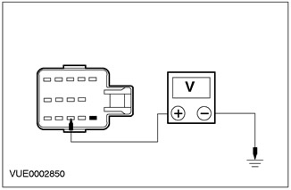
4 Measure the voltage between pin 3 C458 of the hazard warning light button, circuit 15S-LG1 (green-yellow) And «weight». |
|
• Is there a voltage pulse present? |
|
|
→ Yes |
|
|
Go to J4 |
|
|
→ No |
|
|
Go to J7 |
|
|
J4: INSTRUMENT PANEL VOLTAGE CHECK |
|
|
1 Enter the OFF position. |
|
|
2 Disconnect the C809 instrument panel. |
|
|
3 Drive the ON position. |
|
|
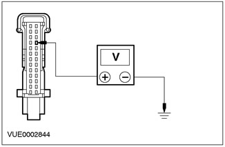
4 Measure voltage between pin 23 C809 of instrument panel, circuit 49S-LG15 (black and blue), And «weight». |
|
• Is the voltage greater than 10 V? |
|
|
→ Yes |
|
|
Go to J6 |
|
|
→ No |
|
|
Go to J5 |
|
|
J5: 49-LG15 ELECTRICAL CIRCUIT CHECK (BLACK-BLUE) FOR A BREAK |
|
|
1 Enter the OFF position. |
|
|
2 Disconnect the C458 hazard warning light button. |
|
|
3 Measure the resistance between pin 23 C809 of instrument panel, circuit 49-LG15 (black and blue), on the wiring side, and pin 12 of connector C458 of the hazard warning light button. |
|
• Is the resistance less than 5 ohms? |
|
|
→ Yes |
|
|
INSTALL a new hazard warning light switch. CHECK the system is working properly. |
|
|
→ No |
|
|
REPAIR the electrical circuit. Check the correct operation of the system. |
|
|
J6: INSTRUMENT PANEL GROUND CHECK |
|
|
1 Disconnect the C809 instrument panel. |
|
|
2 Measure the resistance between pin 2 of instrument panel connector C809, circuit 91-GG14 (black and blue), And «weight». |
|
• Is the resistance less than 5 ohms? |
|
|
→ Yes |
|
|
INSTALL a new indicator light bulb. For more information, refer to Instrument panel available in this section. CHECK the system is working properly. |
|
|
→ No |
|
|
REPAIR the electrical circuit. Check the correct operation of the system. |
|
|
J7: 15S-LG1 ELECTRICAL CIRCUIT CHECK (GREEN YELLOW) FOR A BREAK |
|
|
1 Using a digital multimeter, measure the resistance between pin 3 of connector C458 of the hazard warning light button, circuit 15S-LG1 (green-yellow), and pin 1 of connector C459 of the multifunction switch. |
|
• Is the resistance less than 5 ohms? |
|
|
→ Yes |
|
|
Go to J8 |
|
|
→ No |
|
|
Repair the electrical circuit. Check the correct operation of the system. |
|
|
J8: CENTRAL JUNCTION BOX VOLTAGE CHECK (CJB) |
|
|
1 Enter the OFF position. |
|
|
2 Disconnect the C459 multifunction switch. |
|
|
3 Drive the ON position. |
|
|
4Measure the voltage between pin 2 of connector C459 of multifunction switch circuit 15-LG27 (green-black), And «weight». |
|
• Is there a voltage pulse present? |
|
|
→ Yes |
|
|
INSTALL a new multifunction switch. Check the correct operation of the system. |
|
|
→ No |
|
|
Go to J9 |
|
|
J9: CENTRAL JUNCTION BOX CHECK (CJB) FOR A BREAK |
|
|
1 Disconnect C15 CJB. |
|
|
2 Measure the resistance between pin 3 of connector C15 CJB, circuit 15-LG27 (green-black), and pin 2 of connector C459 of the multifunction switch. |
|
• Is the resistance less than 5 ohms? |
|
|
→ Yes |
|
|
REPAIR or INSTALL a new CJB. CHECK the system is working properly. |
|
|
→ No |
|
|
REPAIR the electrical circuit. Check the correct operation of the system. |
|
|
J10: RIGHT TURN SIGNAL FUNCTION TEST |
|
|
1 Set the turn signal switch to the right turn signal. |
|
|
• Is the right turn signal indicator light on? |
|
|
→ Yes |
|
|
The car is correct. |
|
|
→ No |
|
|
Go to J11 |
|
|
J11: RIGHT TURN SIGNAL LAMP TEST |
|
|
1 Check the operation of the right turn signal lamp. |
|
|
• Is the right turn signal light on? |
|
|
→ Yes |
|
|
Go to J12 |
|
|
→ No |
|
|
See Section 417-01 for more information. |
|
|
J12: VOLTAGE CHECK ON HAZARD LIGHT BUTTON |
|
|
1 Enter the OFF position. |
|
|
2 Disconnect the C458 hazard warning light button. |
|
|
3 Drive the ON position. |
|
|
4 Measure the voltage between pin 6 C458 of the hazard warning light button, circuit 15S-LG2 (green-blue), And «weight». |
|
• Is the voltage greater than 10 V? |
|
|
→ Yes |
|
|
Go to J13 |
|
|
→ No |
|
|
Go to J15 |
|
|
J13: INSTRUMENT PANEL VOLTAGE CHECK |
|
|
1 Enter the OFF position. |
|
|
2 Disconnect the C809 instrument panel. |
|
|
3 Drive the ON position. |
|
|
4 Measure the voltage between pin 17 of instrument cluster connector C809, circuit 49S-LG22 (yellow-blue), And «weight». |
|
• Is the voltage greater than 10 V? |
|
|
→ Yes |
|
|
Go to J6 |
|
|
→ No |
|
|
Go to J14 |
|
|
J14: 49S-LG22 ELECTRICAL CIRCUIT CHECK (YELLOW-BLUE) AND 49S-LG4 FOR A BREAK |
|
|
1 Measure the resistance between pin 17 of instrument cluster connector C809, circuit 49S-LG22 (yellow-blue), and pin 14 of connector C458 of the hazard warning light button, circuit 49S-LG4 (red-blue). |
|
• Is the resistance less than 5 ohms? |
|
|
→ Yes |
|
|
INSTALL a new hazard warning light button. CHECK the system is working properly. |
|
|
→ No |
|
|
REPAIR the electrical circuit. Check the correct operation of the system. |
|
|
J15: 15S-LG2 ELECTRICAL CIRCUIT CHECK (GREEN-BLUE) FOR A BREAK |
|
|
1 Enter the OFF position. |
|
|
2 Disconnect the C458 hazard warning light button. |
|
|
3 Measure the resistance between pin 6 of connector C458 of the hazard warning light button, circuit 15S-LG2 (green-blue), and pin 3 of connector C459 of the multifunction switch. |
|
• Is the resistance less than 5 ohms? |
|
|
→ Yes |
|
|
Go to J8 |
|
|
→ No |
|
|
Repair the electrical circuit. Check the correct operation of the system. |
|
PINPOINT TEST K: CHARGING INDICATOR LIGHT ON
|
STATES |
DETAILS/RESULTS/ACTIONS |
|
K1: CHARGING LAMP FUNCTIONAL CHECK |
|
|
1 Activate instrument cluster self-test number 3, warning lights on. |
|
|
• Is the charging system indicator light on? |
|
|
→ Yes |
|
|
The charging system is faulty. See Section 414-02 for more information. |
|
|
→ No |
|
|
INSTALL a new bulb. For more information, refer to Instrument panel available in this section. |
|
PINPOINT TEST L: EMISSION CONTROL WARNING LIGHT (MIL) NOT FUNCTIONAL / PERMANENTLY ON
|
STATES |
DETAILS/RESULTS/ACTIONS |
|
L1: EMISSION CONTROL LAMP CONTROL |
|
|
1 Drive the ON position. |
|
|
2 check the emission control system malfunction indicator lamp (MIL). |
|
|
• Is the MIL indicator light on? |
|
|
→ Yes |
|
|
Go to L3 |
|
|
→ No |
|
|
Go to L2 |
|
|
L2: EMISSION CONTROL LAMP FUNCTIONAL CHECK |
|
|
1 Activate instrument cluster self-test number 3, warning lights on. |
|
|
• Is the MIL indicator light on? |
|
|
→ Yes |
|
|
Go to L3 |
|
|
→ No |
|
|
INSTALL a new bulb. For more information, refer to Instrument panel available in this section. |
|
|
L3: EMISSION CONTROL LAMP CONTINUATION CHECK |
|
|
1 Cycle the ignition switch leaving the ignition switch in position II. |
|
|
• Does the MIL indicator go out within 10 seconds? |
|
|
→ Yes |
|
|
The system is correct. |
|
|
→ No |
|
|
REFER to WDS. |
|
PINPOINT TEST M: ABS WARNING LIGHT DOES NOT WORK
|
STATES |
DETAILS/RESULTS/ACTIONS |
|
M1: SYSTEM OPERATION CHECK |
|
|
1 Drive the ON position. |
|
|
2 Check the ABS warning light. |
|
|
• Is the ABS warning light on? |
|
|
→ Yes |
|
|
If the control lamp lights up for three seconds, the car is serviceable. If the warning light stays on, diagnose the ABS system using WDS. |
|
|
→ No |
|
|
Navigate to M2 |
|
|
M2: CHECK ABS LAMP FUNCTION |
|
|
1 Activate instrument cluster self-test number 3, warning lights on. |
|
|
• Is the ABS warning light on? |
|
|
→ Yes |
|
|
Go to M3 |
|
|
→ No |
|
|
INSTALL a new bulb. For more information, refer to Instrument panel available in this section. CHECK the system is working properly. |
|
|
M3: INSTRUMENT PANEL CONFIGURATION CHECK |
|
|
1 |
|
|
• Is the instrument panel configured correctly? |
|
|
→ Yes |
|
|
Go to M4 |
|
|
→ No |
|
|
To configure the module, REFER to the option «Programmable Module Installer» wds. CHECK the system is working properly. |
|
|
M4: 31S-CF28 ELECTRICAL CIRCUIT CHECK (BLACK-RED) FOR A BREAK |
|
|
1 Enter the OFF position. |
|
|
2 Disconnect the C809 instrument panel. |
|
|
3 Disconnect the C385 ABS control module. |
|
|
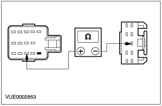
4 Measure the resistance between pin 15 of connector C385 of the ABS control module, circuit 31S-CF28 (black and red), wiring side, and pin 18 of instrument panel connector C809, circuit 31S-CF28 (black and red), from the side of the electrical wiring. |
|
• Is the resistance less than 5 ohms? |
|
|
→ Yes |
|
|
INSTALL a new instrument panel. CHECK the system is working properly. |
|
|
→ No |
|
|
REPAIR the electrical circuit. CHECK the system is working properly. |
|
PINPOINT TEST N: AUXILIARY INPUT ERROR
|
STATES |
DETAILS/RESULTS/ACTIONS |
|
N1: AUXILIARY INPUT CHECK - IGNITION POSITION II |
|
|
1 Drive the ON position. |
|
|
2 Activate instrument panel self-test number 16, starting status. |
|
|
• Is the display showing Cr-L? |
|
|
→ Yes |
|
|
Auxiliary channel error. Go to N2 |
|
|
→ No |
|
|
Go to N3 |
|
|
N2: FUSE CHECK 59 (7.5 A) |
|
|
1 Check fuse 59 (7.5 A). |
|
|
• Is the fuse good? |
|
|
→ Yes |
|
|
Go to N3 |
|
|
→ No |
|
|
INSTALL new fuse 59 (7.5 A). Check the correct operation of the system. |
|
|
N3: AUXILIARY INPUT CHECK - IGNITION POSITION III |
|
|
1 Momentarily turn the ignition to position 3 (cranking position of the crankshaft) and check for any input signal changes in self-test 16. |
|
|
• Does the input signal change to Cr-L? |
|
|
→ Yes |
|
|
INSTALL a new instrument panel. CHECK the system is working properly. |
|
|
→ No |
|
|
REPAIR the auxiliary circuit circuit. CHECK the system is working properly. |
|
Visitor comments