|
STATES |
DETAILS/RESULTS/ACTIONS |
|
A1: PARKING LIGHTS FUNCTIONAL CHECK |
|
|
1 Enter the OFF position. |
|
|
2 Set the parking light switch to the ON position (on). |
|
|
• Are the marker lights and license plate lights on? |
|
|
→ Yes |
|
|
INSTALL a new headlight switch. CHECK the system is working properly. |
|
|
→ No |
|
|
CHECK fuse 32 (10 A). |
|
|
If the fuse is good, troubleshoot the exterior lights. See Section 417-01 for more information. |
|
|
If the fuse is blown, INSTALL a new fuse. CHECK the system is working properly. If the fuse fails again, CHECK for a short to ground, REPAIR if necessary. |
|
PINPOINT TEST B: INSTRUMENT PANEL LIGHT DOES NOT WORK
|
STATES |
DETAILS/RESULTS/ACTIONS |
|
B1: INSTRUMENT PANEL LIGHT CHECK |
|
|
1 Set the headlight switch to the ON position. |
|
|
• Only the instrument panel illumination does not work? |
|
|
→ Yes |
|
|
Set the headlight switch to the OFF position. Navigate to B2 |
|
|
On vehicles with a Duratec ST engine, if the oil pressure and oil temperature cluster lights do not work. Go to B4. |
|
|
→ No |
|
|
If outdoor lights are not working, see Section 417-01 for more information. If the illumination of all controls does not work, GO to Pinpoint Test A. |
|
|
B2: ELECTRICAL CIRCUIT CHECK 29S-GG14 (ORANGE) FOR VOLTAGE |
|
|
1 Enter the OFF position. |
|
|
2 Disconnect the C809 instrument panel. |
|
|
3 Make sure the instrument illumination dimmer is set to the maximum brightness setting. |
|
|
4 Set the headlight switch to the ON position. |
|
|
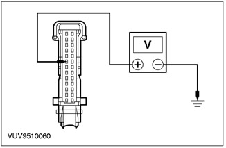
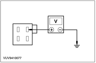
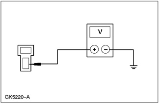
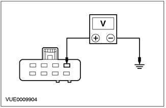
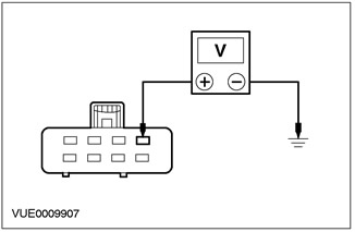
5 Measure the voltage between pin 3 C809 of instrument panel, circuit 29S-GG14 (orange), from the wiring side, and "ground". |
|
• Is the voltage greater than 10 V? |
|
|
→ Yes |
|
|
Go to B3. |
|
|
→ No |
|
|
Repair the electrical circuit. CHECK the system is working properly. |
|
|
B3: 91-GG14 ELECTRICAL CIRCUIT CHECK (BLACK AND ORANGE) FOR A BREAK |
|
|
1 Set the headlight switch to the OFF position. |
|
|
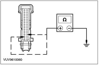
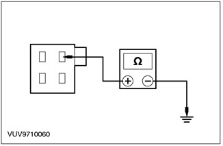
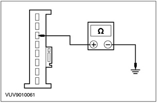
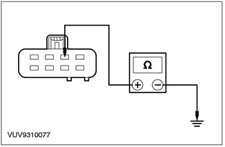
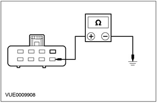
2 Measure the resistance between pin 2 C809 of instrument panel, circuit 91-GG14 (black-orange), from the wiring side, and "ground". |
|
• Is the resistance less than 5 ohms? |
|
|
→ Yes |
|
|
CHECK the condition of the lamps. INSTALL new bulbs if necessary. If the bulbs are OK, INSTALL a new instrument panel. See Section 413-01 for more information. CHECK the system is working properly. |
|
|
→ No |
|
|
REPAIR the electrical circuit. CHECK the system is working properly. |
|
|
B4: CHECK THE OIL PRESSURE AND OIL TEMPERATURE DISPLAY BACKLIGHT |
|
|
NOTE: The oil pressure and oil temperature display backlight harness is connected through the main instrument cluster backlight harness. If the illumination of the main instrument panel is defective, the illumination of the oil pressure and oil temperature display may also not function. INSPECT the main instrument panel illumination circuit before attempting to diagnose the oil pressure and oil temperature display illumination. |
|
|
1 Set the headlight switch to the ON position. |
|
|
• Only the illumination of the oil pressure and oil temperature cluster does not work? |
|
|
→ Yes |
|
|
Set the headlight switch to the OFF position. Go to B5 |
|
|
→ No |
|
|
If outdoor lights are not working, see Section 417-01 for more information. If all controls do not illuminate, GO to Pinpoint Test A. |
|
|
B5: 29S-GE6A ELECTRICAL CIRCUIT CHECK (ORANGE YELLOW) FOR VOLTAGE |
|
|
1 Enter the OFF position. |
|
|
2 Disconnect the C853 oil pressure and oil temperature unit. |
|
|
3 Make sure the instrument illumination dimmer is set to the maximum brightness setting. |
|
|
4 Set the headlight switch to the ON position. |
|
|
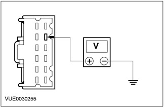
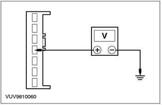
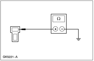
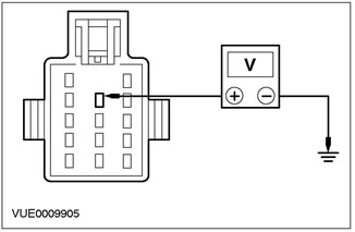
5 Measure the voltage between pin 8 C853 oil pressure and oil temperature display circuit 29S-GE6A (orange yellow), from the wiring side, and "ground". |
|
• Is the voltage greater than 10 V? |
|
|
→ Yes |
|
|
Go to B6. |
|
|
→ No |
|
|
REPAIR the electrical circuit. CHECK the system is working properly. |
|
|
B6: 91-GE6 ELECTRICAL CIRCUIT CHECK (BLACK YELLOW) FOR A BREAK |
|
|
1 Set the headlight switch to the OFF position. |
|
|
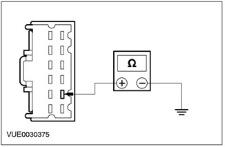
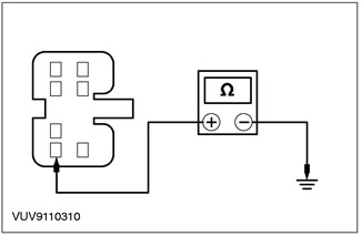
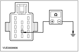
2 Measure the resistance between pin 11 C853 of the instrument panel, circuit 91-GE6 (black and yellow), from the wiring side, and "ground". |
|
• Is the resistance less than 5 ohms? |
|
|
→ Yes |
|
|
CHECK the condition of the lamps. INSTALL new bulbs if necessary. If the bulbs are OK, INSTALL a new oil pressure and oil temperature display. See Section 413-01 for more information. CHECK the system is working properly. |
|
|
→ No |
|
|
Repair the electrical circuit. CHECK the system is working properly. |
|
PINPOINT TEST C: CLIMATE CONTROL PANEL LIGHT DOES NOT WORK
|
STATES |
DETAILS/RESULTS/ACTIONS |
|
C1: CIRCUIT VOLTAGE TEST 29S-LH27 (ORANGE GREEN) |
|
|
1 Enter the OFF position. |
|
|
2 Disconnect the C493 climate control panel backlight. |
|
|
3 Make sure the instrument illumination dimmer is set to the maximum brightness setting. |
|
|
4 Set the headlight switch to the ON position. |
|
|
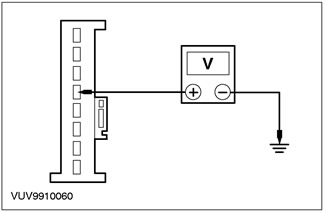
5 Measure the voltage between pin 2 C493 climate control panel backlight, circuit 29S-LH27 (orange green), from the wiring side, and "ground". |
|
• Is the voltage greater than 10 V? |
|
|
→ Yes |
|
|
Go to C2. |
|
|
→ No |
|
|
REPAIR the electrical circuit. CHECK the system is working properly. |
|
|
C2: 31-LH27 ELECTRICAL CIRCUIT CHECK (BLACK) FOR A BREAK |
|
|
1 Measure the resistance between pin 1 C493 of the climate control backlight of circuit 31-LH27 (black), from the wiring side, and "ground". |
|
• Is the resistance less than 5 ohms? |
|
|
→ Yes |
|
|
INSTALL a new climate control panel light. CHECK the system is working properly. |
|
|
→ No |
|
|
REPAIR the electrical circuit. CHECK the system is working properly. |
|
PINPOINT TEST D: AUDIO LIGHT DOES NOT WORK
|
STATES |
DETAILS/RESULTS/ACTIONS |
|
D1: 29S-LK34 AUDIO BACKLIGHT VOLTAGE CHECK (ORANGE-BLUE) |
|
|
1 Enter the OFF position. |
|
|
2 Disconnect the C443 radio. |
|
|
3 Make sure the instrument illumination dimmer is set to the maximum brightness setting. |
|
|
4 Set the headlight switch to the ON position. |
|
|
5 Measure the voltage between pin 4 C443 of the audio unit, circuit 29S-LK34 (orange-black), from the wiring side, and "ground". |
|
• Is the voltage greater than 10 V? |
|
|
→ Yes |
|
|
INSTALL a new audio unit. See Section 415-01 for more information. CHECK the system is working properly. |
|
|
→ No |
|
|
Repair the electrical circuit. CHECK the system is working properly. |
|
PINPOINT TEST E: GEAR SHIFT LIGHT LIGHT DOES NOT WORK
|
STATES |
DETAILS/RESULTS/ACTIONS |
|
E1: 29S-LK21 ELECTRICAL VOLTAGE TEST (ORANGE-BLACK) |
|
|
1 Make sure the instrument lighting dimmer is set to the maximum brightness setting. |
|
|
2 Set the headlight switch to the ON position. |
|
|
3 Measure the voltage between pin 4 C931 shift lever, circuit 29S-LK21 (orange-black), from the wiring side, and "ground". |
|
• Is the voltage greater than 10 V? |
|
|
→ Yes |
|
|
Go to E2. |
|
|
→ No |
|
|
REPAIR the electrical circuit. CHECK the system is working properly. |
|
|
E2: 31-TA34 ELECTRICAL CIRCUIT CHECK (BLACK) FOR A BREAK |
|
|
1 Measure the resistance between C931 shift lever pin 1, circuit 31-TA34 (black), from the wiring side, and "ground". |
|
• Is the resistance less than 5 ohms? |
|
|
→ Yes |
|
|
INSTALL a new shift lever lamp socket. CHECK the system is working properly. |
|
|
→ No |
|
|
REPAIR the electrical circuit. CHECK the system is working properly. |
|
PINPOINT TEST F: CIGAR LIGHTER LIGHT DOES NOT WORK
|
STATES |
DETAILS/RESULTS/ACTIONS |
|
F1: CHECK CIRCUIT VOLTAGE 29S-LK15 (ORANGE) |
|
|
1 Make sure the instrument lighting dimmer is set to the maximum brightness setting. |
|
|
2 Set the headlight switch to the ON position. |
|
|
3 Measure the voltage between pin 1 C911 cigarette lighter circuit 29S-LK15 (orange), from the wiring side, and "ground". |
|
• Is the voltage greater than 10 V? |
|
|
→ Yes |
|
|
Go to F2. |
|
|
→ No |
|
|
Repair the electrical circuit. CHECK the system is working properly. |
|
|
F2: 31-HA6 CIRCUIT CHECK (BLACK) FOR A BREAK |
|
|
1 Measure the resistance between C912 cigarette lighter pin 1, circuit 31-HA6 (black), from the wiring side, and "ground". |
|
• Is the resistance less than 5 ohms? |
|
|
→ Yes |
|
|
INSTALL a new cigarette lighter socket. CHECK the system is working properly. |
|
|
→ No |
|
|
REPAIR the electrical circuit. CHECK the system is working properly. |
|
PINPOINT TEST G: DOOR LOCK/UNLOCK SWITCH LIGHT DOES NOT WORK
|
STATES |
DETAILS/RESULTS/ACTIONS |
|
G1: CHECKING VOLTAGE SUPPLIED TO A DOOR LOCK/UNLOCK SWITCH ISN'T WORKING |
|
|
1 Enter the OFF position. |
|
|
2 Detach the non-working switch. |
|
|
3 Drive the ON position. |
|
|
4 Make sure the instrument illumination dimmer is set to the maximum brightness setting. |
|
|
5 Set the headlight switch to the ON position. |
|

|
6 Measure the voltage between pin 10 C41 door lock/unlock switch circuit 15-LH28 (green-yellow) (left-hand side) / pin 17 C43, electrical circuit 15-LH42 (green-blue) (Right side), from the wiring side, and "ground". |
|
• Is the voltage greater than 10 V? |
|
|
→ Yes |
|
|
Go to G2. |
|
|
→ No |
|
|
REPAIR the electrical circuit (And) 15-LH28 (green-yellow) / electrical circuit 15-LH42 (green-blue). CHECK the system is working properly. |
|
|
G2: CHECKING THE GROUND CIRCUIT OF THE OFF SWITCH FOR AN OPEN |
|
|
1 Enter the OFF position. |
|
|
2 Measure the resistance between C41 pin 2 of the door lock/unlock switch circuit 31-DA11 (black) (left-hand side) / pin 2 C43, electrical circuit 31-DA12 (black) (Right side), from the wiring side, and "ground" |
|
• Is the resistance less than 5 ohms? |
|
|
→ Yes |
|
|
INSTALL a new door lock/unlock switch. CHECK the system is working properly. |
|
|
→ No |
|
|
REPAIR the electrical circuit (And) 31-DA11/ 31-DA12 (black). CHECK the system is working properly. |
|
PINPOINT TEST H: TRACTION CONTROL SWITCH LIGHT DOES NOT WORK.
|
STATES |
DETAILS/RESULTS/ACTIONS |
|
H1: 29S-LH45 ELECTRICAL VOLTAGE TEST (ORANGE-WHITE) |
|
|
1 Disconnect the C717 traction control switch. |
|
|
2 Make sure the instrument illumination dimmer is set to the maximum brightness setting. |
|
|
3 Set the headlight switch to the ON position. |
|
|
4 Measure the voltage between pin 8 C717 of circuit 29S-LH45 (orange white), from the wiring side, and "ground". |
|
• Is the voltage greater than 10 V? |
|
|
→ Yes |
|
|
Go to H2. |
|
|
→ No |
|
|
REPAIR the electrical circuit. CHECK the system is working properly. |
|
|
H2: 91-LH45 ELECTRICAL CIRCUIT CHECK (BLACK AND WHITE) FOR A BREAK |
|
|
1 Measure the resistance between pin 7 C717, circuit 91-LH45 (black and white), from the wiring side, and "ground". |
|
• Is the resistance less than 5 ohms? |
|
|
→ Yes |
|
|
INSTALL a new traction control off switch. CHECK the system is working properly. |
|
|
→ No |
|
|
Repair the electrical circuit. CHECK the system is working properly. |
|
PINPOINT TEST I: HAZARD LIGHT BUTTON LIGHT DOES NOT WORK
|
STATES |
DETAILS/RESULTS/ACTIONS |
|
I1: CIRCUIT VOLTAGE TEST 29S-LG8A (ORANGE) |
|
|
1 Disconnect the C458 hazard warning light button. |
|
|
2 Make sure the instrument illumination dimmer is set to the maximum brightness setting. |
|
|
3 Set the headlight switch to the ON position. |
|
|
4 Measure the voltage between pin 4 C458 of the hazard warning light button, circuit 29S-LG8A (orange), from the wiring side, and "ground". |
|
• Is the voltage greater than 10 V? |
|
|
→ Yes |
|
|
Go to I2. |
|
|
→ No |
|
|
REPAIR the electrical circuit. CHECK the system is working properly. |
|
|
I2: 91-LG8 ELECTRICAL CIRCUIT CHECK (BLACK AND ORANGE) FOR A BREAK |
|
|
1 Measure the resistance between pin 10 C458 of the hazard warning light button, circuit 91-LG8 (black-orange), from the wiring side, and "ground". |
|
• Is the resistance less than 5 ohms? |
|
|
→ Yes |
|
|
INSTALL a new hazard warning light button. CHECK the system is working properly. |
|
|
→ No |
|
|
REPAIR the electrical circuit. CHECK the system is working properly. |
|
PINPOINT TEST J: HEATED FRONT SEAT SWITCH LIGHT DOES NOT WORK
|
STATES |
DETAILS/RESULTS/ACTIONS |
|
J1: CHECKING THE ELECTRICAL CIRCUIT OF THE IN-OPERATE HEATED SEAT SWITCH FOR VOLTAGE |
|
|
1 Disconnect Inoperative seat heating switch. |
|
|
2 Make sure the instrument illumination dimmer is set to the maximum brightness setting. |
|
|
3 Set the headlight switch to the ON position. |
|
|
4 Measure the voltage between pin 8 C694 of the seat heating switch (left-hand side), electrical circuit 29S-LH29 (orange yellow) / pin 8 C695 (Right side), electrical circuit 29S-LH43 (orange-blue), from the wiring side, and "ground". |
|
• Is the voltage greater than 10 V? |
|
|
→ Yes |
|
|
Go to J2. |
|
|
→ No |
|
|
REPAIR circuit 29S-LH29 (orange yellow) /electric circuit 29S-LH43 (orange-blue) respectively. CHECK the system is working properly. |
|
|
J2: CHECKING THE GROUND CIRCUIT OF THE IN-OPERATE HEATED SEAT SWITCH FOR AN OPEN |
|
|
1 Measure resistance between pin 4 C694 (left-hand side) electrical circuit 31-LH29 (black) / pin 4 C695 (Right side) electrical circuit 31-LH43 (black), from the wiring side, and "ground". |
|
• Is the resistance less than 5 ohms? |
|
|
→ Yes |
|
|
INSTALL a new seat heating switch. CHECK the system is working properly. |
|
|
→ No |
|
|
REPAIR circuit 31-LH29 (black) / electrical circuit 31-LH43 (black) respectively. CHECK the system is working properly. |
|
Visitor comments