|
STATES |
DETAILS/RESULTS/ACTIONS |
|
A1: 29S-GJ1 ELECTRICAL CIRCUIT CHECK (ORANGE-BLUE) FOR A SHORT TO BATTERY POSITIVE TERMINAL |
|
|
1 Disconnect the Horn Relay. |
|
|
• Does the buzzer stop when the relay is disconnected? |
|
|
→ Yes |
|
|
Go to A2 |
|
|
→ No |
|
|
REPAIR circuit 29S-GJ1 (orange-blue), by repairing the short to the positive battery terminal. CHECK the system is working properly. |
|
|
A2: 91S-GJ7 ELECTRICAL CIRCUIT CHECK (BLACK-BLUE) FOR A SHORT TO « GROUND » |
|
|
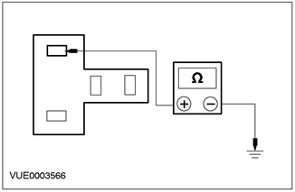
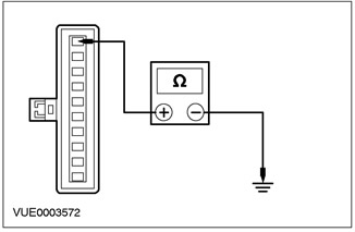
1 Using a DMM, measure the resistance between pin 2 of the horn relay, circuit 91S-GJ7 (black and blue), and "mass". |
|
• Is the resistance greater than 10,000 ohms? |
|
|
→ Yes |
|
|
INSTALL a new horn relay. CHECK the system is working properly. |
|
|
→ No |
|
|
Go to A3 |
|
|
A3: CHECKING THE STEERING WHEEL HORN SWITCH |
|
|
1 Remove the lower steering column cover. |
|
|
2 Disconnect the C896 airbag sliding contact. |
|

|
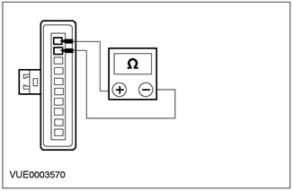
3 Using a digital multimeter, measure the resistance between pins 1 and 2 of airbag wiper connector C896, component side. |
|
• Is the resistance greater than 10,000 ohms? |
|
|
→ Yes |
|
|
Install a new relay. CHECK the system is working properly. |
|
|
→ No |
|
|
Go to A4 |
|
|
A4: CHECKING THE STEERING WHEEL HORN SWITCH |
|
|
WARNING: To properly deactivate the airbag, refer to the procedure in Section 501-20B. |
|
|
1 Remove the airbag. See Section 501-20A / 501-20B for more information. |
|
|
2 Disconnect the C920 horn switch. |
|
|
3 Using a DMM, measure the resistance between pin 1 and pin 2 of the C920 horn switch connector. |
|
• Is the resistance greater than 10,000 ohms? |
|
|
→ Yes |
|
|
INSTALL a new airbag slider. CHECK the system is working properly. |
|
|
→ No |
|
|
INSTALL a new horn switch (ov). CHECK the system is working properly. |
|
PINPOINT TEST B: BEEP DOES NOT BEEP
|
STATES |
DETAILS/RESULTS/ACTIONS |
|
B1: FUSE CHECK 7 (40 A) |
|
|
1 CHECK Fuse 7 (40 A) CJB. |
|
|
• Is the audio unit functioning properly? |
|
|
→ Yes |
|
|
Navigate to B2 |
|
|
→ No |
|
|
REPAIR fuse 7. CHECK system for proper operation. |
|
|
B2: FUSE CHECK 34 (20 A) |
|
|
1 CHECK Fuse 34 (20 A) CJB. |
|
|
• Is the fuse good? |
|
|
→ Yes |
|
|
Go to B3 |
|
|
→ No |
|
|
REPAIR fuse 34. CHECK system for proper operation. |
|
|
B3: HORN RELAY TEST |
|
|
1 Disconnect the Horn Relay. |
|
|
2 Check the relay elements. For more information, refer to Horn Relay available in this section.. |
|
|
• Relay OK? |
|
|
→ Yes |
|
|
Go to B4 |
|
|
→ No |
|
|
INSTALL a new horn relay. CHECK the system is working properly. |
|
|
B4: CJB POWER SUPPLY CHECK |
|
|
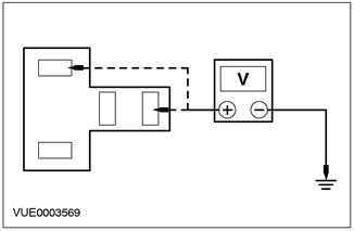
1 Using a DMM, measure the voltage between horn relay pin 1, wiring side, and ground, and pin 3, horn relay, wiring side, and ground. |
|
• Is the voltage always greater than 10 V? |
|
|
→ Yes |
|
|
Go to B5 |
|
|
→ No |
|
|
REPAIR Circuit 30-DA1 (red). CHECK the system is working properly. |
|
|
B5: HORN SWITCH POWER CHECK |
|
|
1 Connect the Horn Relay. |
|
|
2 Disconnect the C896 airbag sliding contact. |
|
|
3 Remove the lower steering column cover. |
|
|
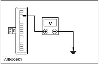
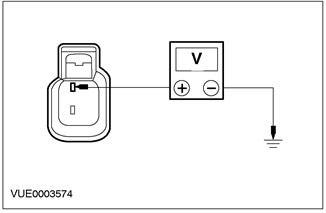
4 Using a digital multimeter, measure the voltage between C896 pin 2 of airbag wiper circuit 91S-GJ7 (black and blue), from the wiring side, and "ground". |
|
• Is the voltage greater than 10 V? |
|
|
→ Yes |
|
|
Go to B6 |
|
|
→ No |
|
|
REPAIR circuit 91S-GJ7 (black and blue), CHECK the system is working properly. |
|
|
B6: HORN SWITCH GROUND ELECTRICAL CHECK |
|
|
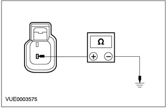
1 Using a digital multimeter, measure the resistance between C896 airbag wiper pin 1, circuit 91-PG30 (black and white), from the wiring side, and "ground". |
|
• Is the resistance less than 5 ohms? |
|
|
→ Yes |
|
|
Go to B7 |
|
|
→ No |
|
|
REPAIR circuit 91-PG30 (black and white), CHECK the system is working properly. |
|
|
B7: CHECKING THE FUNCTION OF THE AIR BAG SLIDER |
|
|
1 Using a DMM, measure the resistance between pins 1 and 2 of airbag wiper connector C896, element side. Take readings with the switch pressed and with the switch not pressed. |
|
• Is the resistance greater than 10,000 ohms with the switch off and less than 5 ohms with the switch pressed? |
|
|
→ Yes |
|
|
Go to B9 |
|
|
→ No |
|
|
Go to B8 |
|
|
B8: HORN SWITCH TEST |
|
|
WARNING: To properly deactivate the airbag, refer to the procedure in Section 501-20B. |
|
|
1 Remove the airbag. See Section 501-20A / 501-20B for more information. |
|
|
2 Disconnect the C982 horn switch. |
|

|
3 Using a DMM, measure the resistance between pins 1 and 2 of connector C982 of the horn switch. Take readings with the switch pressed and with the switch not pressed. |
|
• Is the resistance greater than 10,000 ohms with the switch off and less than 5 ohms with the switch pressed? |
|
|
→ Yes |
|
|
Install a new airbag slider. CHECK the system is working properly. |
|
|
→ No |
|
|
INSTALL a new switch (And) sound signal. CHECK the system is working properly. |
|
|
B9: HORN POWER SUPPLY CHECK (OV) |
|
|
1 Connect the C896 airbag slider. |
|
|
2 Connect the C920 horn switch. |
|
|
3 Disconnect the C77 horn. |
|
|
4 Using a digital multimeter, measure the voltage between C77 pin 1 of the horn (ov), electrical circuit 29S-GJ1 (orange-blue), from the wiring side, and "ground" by pressing the horn switch. |
|
• Is the voltage greater than 10 V? |
|
|
→ Yes |
|
|
Go to B10 |
|
|
→ No |
|
|
REPAIR circuit 29S-GJ1 (orange-white). CHECK the system is working properly. |
|
|
B10: HORN GROUND ELECTRICAL CIRCUIT CHECK (OV) |
|
|
1 Using a DMM, measure the resistance between C77 pin 2 of the horn (ov), electric circuit 31-GJ1 (black), from the wiring side, and "ground". |
|
• Is the resistance less than 5 ohms? |
|
|
→ Yes |
|
|
INSTALL a new horn (s). CHECK the system is working properly. |
|
|
→ No |
|
|
REPAIR Circuit 31-GJ1 (black). CHECK the system is working properly. |
|
Checking the elements
1. Remove the relay.
2. Connect one end of the auxiliary wire to pin 85 of the relay. Connect the other end of the wire to «mass».
3. Connect one end of the second auxiliary wire to pin 86 of the relay.
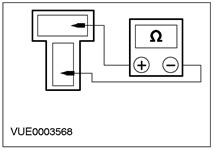
4. Connect one ohmmeter lead to pin 30 of the relay. Connect the second wire to pin 87 of the relay. Determine the resistance.
5. Momentarily touch the free end of the wire connected to pin 86 to the positive battery terminal. In this case, a distinct click should be heard, and the resistance measured with an ohmmeter should drop to zero.
6. If a Pinpoint test was performed, return to the Pinpoint test.
Visitor comments