|
STATES |
DETAILS/RESULTS/ACTIONS |
|
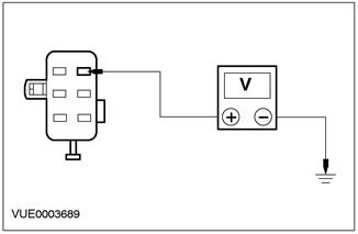
A1: CHECK VOLTAGE IN CIRCUIT 29-GB6 (ORANGE/YELLOW) |
|
|
1Enter the OFF position. |
|
|
2Disconnect the C460 Clock. |
|
|
3Using a digital multimeter, measure the voltage between pin 6 of the C460 clock, circuit 29-GB6 (orange/yellow), harness side and ground. |
|
• Is the voltage more than 10V? |
|
|
→ Yes |
|
|
Go to A2 Proceed to PINPOINT TEST A |
|
|
→ No |
|
|
REPAIR electrical circuit 29-GB6 (orange/yellow), CHECK correct system operation. |
|
|
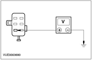
A2: CHECK VOLTAGE IN CIRCUIT 15-GB6 (GREEN/YELLOW) |
|
|
1Enter the ON position. |
|
|
2Using a digital multimeter, measure the voltage between pin 1 of C460, circuit 15-GB6 (green/yellow), harness side and ground. |
|
• Is the voltage more than 10V? |
|
|
→ Yes |
|
|
Go to A3 Proceed to PINPOINT TEST A |
|
|
→ No |
|
|
CHECK fuse 59 (7.5A). If the fuse is blown, INSTALL a new fuse. CHECK for proper system operation. If the fuse blows again, CHECK for a short to ground. If the fuse is good, REPAIR circuit 15-GB6 (Green/Yellow). CHECK for proper system operation. |
|
|
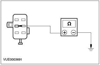
A3: CHECK ELECTRICAL CIRCUIT 91-GB6 (BLACK/YELLOW) FOR OPEN |
|
|
1Enter the OFF position. |
|
|
2Using a digital multimeter, measure the resistance between pin 2 of C460, circuit 91-GB6 (black/yellow), harness side and ground. |
|
• Is the resistance less than 5 ohms? |
|
|
→ Yes |
|
|
SET the new clock. CHECK that the system is working properly. |
|
|
→ No |
|
|
REPAIR electrical circuit 91-GB6 (black/yellow). CHECK system operation for proper operation. |
|
[The original text is provided on an online resource: fordbook]