|
STATES |
DETAILS/RESULTS/ACTIONS |
|
A1: CHECK THE OPERATION OF THE OUTDOOR TEMPERATURE LIGHT |
|
|
1 Enter the Information and Message Center Self-diagnostic Mode, Check number one: enable segments. |
|
|
• Does the outdoor temperature indicator light come on? |
|
|
→ Yes |
|
|
Go to A2 Go to PINPOINT TEST A |
|
|
→ No |
|
|
INSTALL a new information and message center. For more information, please refer to the Message Center available in this section. CHECK the system is working properly. |
|
|
A2: CHECK INPUT SIGNAL FROM OUTDOOR AIR TEMPERATURE SENSOR |
|
|
1 Enter the information and message center self-diagnosis mode, Check number six, air temperature input sensor status. |
|
|
• Is the outdoor temperature sensor display showing the value in°C? |
|
|
→ Yes |
|
|
INSTALL a new information and message center. For more information, please refer to the Message Center available in this section.. |
|
|
→ No |
|
|
Go to A3 Go to PINPOINT TEST A |
|
|
A3: INSPECT ELECTRICAL CIRCUIT 9-GE38 (BROWN/YELLOW) TO BREAK |
|
|
1 Detach Information and Message Center - C467. |
|
|
2 Disconnect the outdoor temperature sensor - C974. |
|
|
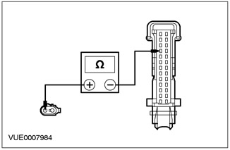
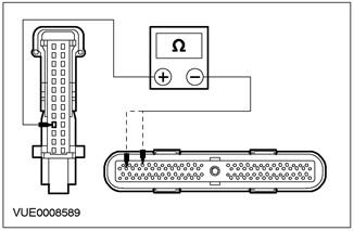
3 Using a digital multimeter, measure the resistance between pin 10 C467 of the information and communication center, circuit 9-GE38 (brown/yellow) on the wiring side, and pin 2 C974 of the outdoor temperature sensor, on the wiring side. |
|
• Is the resistance less than 5 ohms? |
|
|
→ Yes |
|
|
Go to A4 Go to PINPOINT TEST A |
|
|
→ No |
|
|
REPAIR circuit 9-GE38 (brown/yellow). CHECK the system is working properly. |
|
|
A4: INSPECT ELECTRICAL CIRCUIT 8-GE38 (WHITE/BLACK) BREAK |
|
|
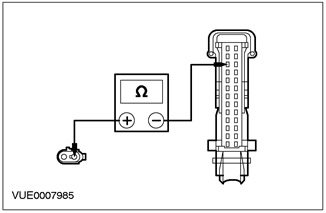
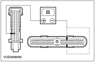
1 Using a digital multimeter, measure the resistance between pin 11 C467 of the information and message center, circuit 8-GE38 (white/black) on the wiring side, and pin 1 C974 of the outdoor temperature sensor, on the wiring side. |
|
• Is the resistance less than 5 ohms? |
|
|
→ Yes |
|
|
INSTALL a new outdoor temperature sensor. CHECK the system is working properly. |
|
|
→ No |
|
|
REPAIR circuit 8-GE38 (white/black). CHECK the system is working properly. |
|
PINPOINT TEST B: PILOT LIGHT ON PERMANENTLY - OUTDOOR TEMPERATURE
|
STATES |
DETAILS/RESULTS/ACTIONS |
|
B1: CHECK INPUT SIGNAL FROM OUTDOOR AIR TEMPERATURE SENSOR |
|
|
1 Make sure the outdoor temperature is above 5°C before performing this test. |
|
|
2 Enter the information and message center self-diagnosis mode, test number six, turn on the segments. |
|
|
• Is the outdoor temperature sensor reading above 5°C? |
|
|
→ Yes |
|
|
INSTALL a new information and message center. For more information, please refer to the Message Center available in this section. CHECK the system is working properly. |
|
|
→ No |
|
|
INSTALL a new outdoor temperature sensor. |
|
PINPOINT TEST C: WARNING LIGHT DOES NOT WORK - WASHER FLUID LEVEL WARNING LIGHT
|
STATES |
DETAILS/RESULTS/ACTIONS |
|
C1: CHECK WASHER FLUID LEVEL FUNCTION |
|
|
1 Enter Information and Message Center Self-diagnostic Mode, Test Number One, Enable Segments. |
|
|
• Does the windshield washer fluid level indicator light come on? |
|
|
→ Yes |
|
|
Go to C2 Go to PINPOINT TEST C |
|
|
→ No |
|
|
INSTALL a new information and message center. For more information, please refer to the Message Center available in this section. CHECK the system is working properly. |
|
|
C2: INSPECT ELECTRICAL CIRCUIT 91S-GC8 (BLACK/ORANGE) TO BREAK |
|
|
1 Detach Information and Message Center - C467. |
|
|
2 Disconnect the Windshield Washer Fluid Level Switch - C813. |
|
|
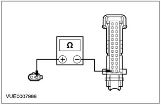
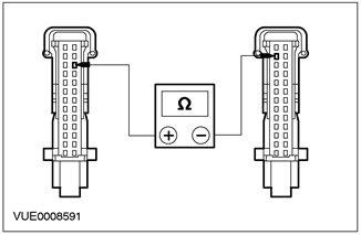
3 Using a DMM, measure the resistance between pin 1 C467 Information and Message Center Circuit 91S-GC8 (black/orange) on the wiring side, and pin 1 C813 washer fluid level switch, on the wiring side. |
|
• Is the resistance less than 5 ohms? |
|
|
→ Yes |
|
|
Go to C3 Go to PINPOINT TEST C |
|
|
→ No |
|
|
REPAIR circuit 91S-GC8 (black/orange). CHECK the system is working properly. |
|
|
C3: INSPECT ELECTRICAL CIRCUIT 91-GC8 (BLACK/ORANGE) BREAK |
|
|
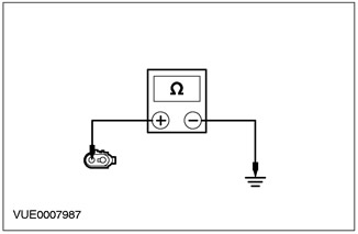
1 Using a DMM, measure the resistance between pin 2 of C813 washer fluid level switch circuit 91-GC8 (black/orange) from the wiring side and "weight". |
|
• Is the resistance less than 5 ohms? |
|
|
→ Yes |
|
|
INSTALL a new washer fluid level switch. CHECK the system is working properly. |
|
|
→ No |
|
|
REPAIR Circuit 91-GC8 (black/orange). CHECK the system is working properly. |
|
PINPOINT TEST D: PILOT LIGHT ON PERMANENTLY - WASHER FLUID LEVEL PILOT LIGHT
|
STATES |
DETAILS/RESULTS/ACTIONS |
|
D1: CHECK INPUT FROM WASHER RESERVOIR LOW SWITCH |
|
|
1 Make sure the washer reservoir is filled with water. |
|
|
2 Detach Information and Message Center - C467. |
|
|
3 Disconnect the Windshield Washer Fluid Level Switch - C813. |
|

|
4 Using a DMM, measure the resistance between pin 1 C467 Information and Message Center Circuit 91S-GC8 (black/orange) on the wiring side and pin 1 C813 of the washer fluid level switch, on the wiring side. |
|
• Is the resistance less than 5 ohms? |
|
|
→ Yes |
|
|
INSTALL a new washer fluid level switch. CHECK the system is working properly. |
|
|
→ No |
|
|
REPAIR circuit 91S-GC8 (black/orange). CHECK the system is working properly. |
|
PINPOINT TEST E: MIDDLE SPEED FUNCTION DOES NOT WORK
|
STATES |
DETAILS/RESULTS/ACTIONS |
|
E1: INSPECT ELECTRICAL CIRCUIT 8-GE21 (WHITE) BREAK |
|
|
1 Detach Information and Message Center - C467. |
|
|
2 Disconnect the Powertrain Control Module (PCM) - C415. |
|
|
3 Using a digital multimeter, measure the resistance between pin 4 C467 of the information and communication center, circuit 8-GE21 (white), on the wiring side, and pin 28 C415 of the powertrain control module (PCM), (gasoline engines) / pin 94 (diesel engines) electrical circuit 8-RE22 (white/green) from the wiring side. |
|
• Is the resistance less than 5 ohms? |
|
|
→ Yes |
|
|
REFER TO FDS 2000. |
|
|
→ No |
|
|
REPAIR circuit 8-GE21 (white) or 8-RE22 (white/green). CHECK the system is working properly. |
|
PINPOINT TEST F: INSTANT FUEL CONSUMPTION DOES NOT WORK
|
STATES |
DETAILS/RESULTS/ACTIONS |
|
F1: INSPECT CIRCUIT 8-GH9 (WHITE/BLUE) BREAK |
|
|
1 Detach Information and Message Center - C467. |
|
|
2 Disconnect the Powertrain Control Module (PCM) - C415. |
|
|
3 Using a DMM, measure the resistance between pin 14 C467 of the information and communication center, circuit 8-GH9 (white/blue), on the wiring side, and pin 43 C415 of the powertrain control module (PCM), (gasoline engines) / pin 95 (diesel engines), electrical circuit 8-GH9 (white/blue) from the wiring side. |
|
• Is the resistance less than 5 ohms? |
|
|
→ Yes |
|
|
REFER TO FDS 2000. |
|
|
→ No |
|
|
REPAIR circuit 8-GH9 (white/blue). CHECK the system is working properly. |
|
PINPOINT TEST G: REMAINING DISTANCE TO REFUELING FUNCTION DOES NOT WORK
|
STATES |
DETAILS/RESULTS/ACTIONS |
|
G1: INSPECT CIRCUIT 7-GE6 (YELLOW) BREAK |
|
|
1 Detach Information and Message Center - C467. |
|
|
2 Disconnect Instrument panel - C809. |
|
|
3 Using a digital multimeter, measure the resistance between pin 24 C467 of the information and communication center, circuit 7-GE6 (yellow), from the wiring side, and pin 12 C809 of the instrument panel, electrical circuit 7-GE6 (yellow) from the wiring side. |
|
• Is the resistance less than 5 ohms? |
|
|
→ Yes |
|
|
See Section 413-01 for more information. |
|
|
→ No |
|
|
REPAIR circuit 7-GE6 (yellow). CHECK the system is working properly. |
|
Visitor comments