|
STATES |
DETAILS/RESULTS/ACTIONS |
|
A1: CHECK THE INPUT VOLTAGE FROM THE HEADLIGHT SWITCH |
|
|
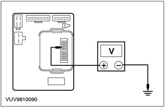
1 Disconnect the Central Timer Module (CTM) C1000. |
|
|
2 Set the headlight switch to "PARKING LIGHTS". |
|
|
3 Set the headlight switch to "NEAR LIGHT!. |
|
|
4 Using a DMM, measure the voltage between C1000 pin 7 and "weight". |
|
• Is the voltage over 10V in both switch positions? |
|
|
→ Yes |
|
|
INSTALL a new CTM. CHECK the system is working properly. |
|
|
→ No |
|
|
If voltage is less than 10V at one switch position, INSTALL a new headlight switch. If the voltage is less than 10 V in both positions. Go to A2 CHECK the system is working properly. |
|
|
A2: CHECK CIRCUIT VOLTAGE 30S-DD40 (RED/GREEN) |
|
|
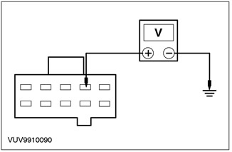
1 Using a digital multimeter, measure the voltage between pin 4 C361 of the central junction box (CJB), electrical circuit 30S-DD40 (red/green), from the wiring side and "weight". |
|
• Is the voltage over 10 V? |
|
|
→ Yes |
|
|
INSTALL the new CJB. CHECK the system is working properly. |
|
|
→ No |
|
|
Go to A3 |
|
|
A3: INSPECT HEADLIGHT SWITCH CIRCUIT FOR OPEN |
|
|
1 Set the headlight switch to the OFF position. |
|
|
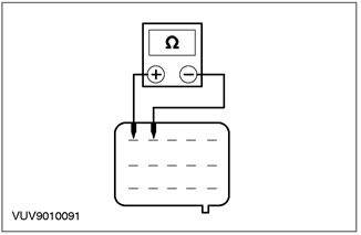
2 Disconnect Headlight Switch - C320. |
|
|
3 Set the headlight switch to "PARKING LIGHTS". |
|
|
4 Using a DMM, measure the resistance between pin 4 and pin 5 of the headlight switch on the wiring side. |
|
|
5 Set the headlight switch to "DOWN LIGHT". |
|
|
6 Using a DMM, measure the resistance between pin 4 and pin 5 of the headlight switch on the wiring side. |
|
• Resistance is less than 5 ohms at the positions "PARKING LIGHTS" And "DOWN LIGHT"? |
|
|
→ Yes |
|
|
REPAIR circuit 30S-DD40 (red/green). CHECK the system is working properly. |
|
|
→ No |
|
|
INSTALL a new headlight switch. CHECK the system is working properly. |
|
Warning Devices — Pinpoint Tests
PINPOINT TEST A: WARNING HORN FALSE IN HEADLIGHT SWITCH ON POSITION
This article is available at russian, bulgarian, belarusian, ukrainian, serbian, croatian, romanian, polish, slovak, hungarian
« Previous articles
Warning devices — diagnostics and checks
Warning devices
Message center — removal and installation
Information and Message Center — Pinpoint Tests
Information and message center — diagnostics and checks
Information and message center
Clock — removal and installation
Watches — Pinpoint Tests
Watches — diagnostics and checks
Watches — description and principle of operation
See other similar articles for Ford cars:
• Removal and installation of components of the panel of devices Ford Mondeo 1 and 2 (1993-2000)
• Control devices Ford Escort 3 (1980-1985)
• Signaling devices Ford Fiesta 4 (1996-1999)
• Replacing lamps in lighting devices Ford Fusion (2002-2012)
• Removal and installation of components of the panel of devices Ford Mondeo 1 and 2 (1993-2000)
• Control devices Ford Escort 3 (1980-1985)
• Signaling devices Ford Fiesta 4 (1996-1999)
• Replacing lamps in lighting devices Ford Fusion (2002-2012)
Link to this page in different formats
HTMLTextBB Code
No comments yet
Focus 2
Focus Turnier 1
Focus 1
- General information
- Vehicle device
- Owner's manual
- Faults en route
- Maintenance
- First maintenance
- Second maintenance
- Applications
- Consumables and spare parts
- Auto mechanic tips
- Power unit
- Engine repair
- Engine seal parts
- Cooling system
- Exhaust system
- Supply system
- Clutch
- Car gearbox
- Front wheel drives
- Chassis
- Front suspension
- Rear suspension
- Steering
- Brake system
- Wheels and tires
- Body and coating
- Body elements
- Side doors
- Tailgate
- Salon elements
- Safety system
- Windshield wipers and washers
- Body Care
- Electrical equipment
- Instruments and motors
- Battery and alternator
- Egnition lock
- Engine management
- Headlights and lighting
- Switches and sensors
- Schematic diagrams
Focus Turnier 1
- General information
- Introduction to guide
- Car care
- Power unit
- Engine repair
- Lubrication system
- Cooling system
- Fuel injection (gasoline)
- Fuel injection (diesel)
- Ignition system
- Power and exhaust system
- Transmission
- Clutch and drive shafts
- Mechanical gearbox
- Automatic gearbox
- Chassis
- Car suspension
- Steering
- Wheels and tires
- Brake system
- Body
- Exterior
- Interior
- Heating and ventilation
- Electrical equipment
- Equipment and devices
- Lighting and signaling
- Power devices
- Electrical circuits
Focus 1
- General information
- Using the manual
- Identification codes
- Power unit
- Engine
- Engine 1.4/1.6 Zetec-SE
- Engine 1.6/1.8/2.0 Zetec-E
- Engine Duratec ST 2.0 l
- Engine Duratec 8V 1.6 l
- Diesel engine 1.8 l
- Engine cooling
- Fuel supply
- Accessory drive
- Launch system
- Ignition system
- Air and vapor
- Engine management
- Exhaust toxicity
- Exhaust system
- Automatic gearbox
- Clutch
- Mechanical gearbox iB5
- Mechanical gearbox MTX-75
- Mechanical gearbox MT285
- Chassis
- Front suspension
- Rear suspension
- Wheels and tires
- Front axle axles
- Brake system
- Hydraulic brake
- Anti-lock braking system
- Steering
- Body and coating
- Body panels
- Body elements
- Salon elements
- Glass, frames and mechanisms
- Windshield wipers and washers
- Car sunroof
- Seat belts
- Body repairs
- Back elements
- Electrical equipment
- Climate control
- Heating and ventilation
- Instruments and control lamps
- Battery and alternator
- Audio system
- Headlights and lighting
- Power distribution
- Electronic Function Group
FordBook.ru © 2014-2024 • Mobile version • Interesting to read • Sitemap: EN BG BY UA RS HR RO PL SK HU • Site search • Contact with administration
Focus 1 • Focus Turnier 1 • Focus 2 • Mondeo 1 • Mondeo 1 and 2 • Mondeo 2 • Mondeo 3 • Mondeo 4 • Escort 3 • Escort 4 • Escort 5 • Fiesta 2 • Fiesta 4 • Taurus 1 and 2 • Fusion • Scorpio 1 • Scorpio 2 • Sierra •
Focus 1 • Focus Turnier 1 • Focus 2 • Mondeo 1 • Mondeo 1 and 2 • Mondeo 2 • Mondeo 3 • Mondeo 4 • Escort 3 • Escort 4 • Escort 5 • Fiesta 2 • Fiesta 4 • Taurus 1 and 2 • Fusion • Scorpio 1 • Scorpio 2 • Sierra •
Visitor comments