|
STATES |
DETAILS/RESULTS/ACTIONS |
|
A1: CHECK REVERSE LIGHT SWITCH |
|
|
1Enter the ON position. |
|
|
2Select reverse gear. |
|
|
• Do the reversing lights work properly? |
|
|
→ Yes |
|
|
Go to A2. |
|
|
→ No |
|
|
For additional information, see Section 417-01. |
|
|
A2: CHECK THE POWER SUPPLY OF THE PARKING ASSIST MODULE |
|
|
1Enter the OFF position. |
|
|
2Disconnect Parking Assist Module - C2100a. |
|
|
3Enter the ON position. |
|
|
4Select reverse gear. |
|
|
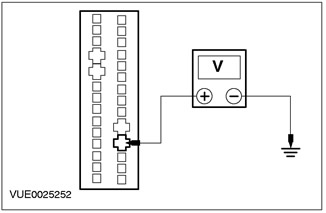
5Measure the voltage between the parking assist module (red) circuit pin 18 on the wiring harness side of the vehicle and ground. |
|
• Is the voltage more than 10V? |
|
|
→ Yes |
|
|
Cars with manual transmission Go to A3 |
|
|
Vehicles with automatic transmission in a block with a leading axle Go to A4 |
|
|
→ No |
|
|
CHECK and REPAIR the circuit between the parking assist module pin 18 C2100a of the circuit (RED) harness side and the reverse lamp switch pin 11 C862 or C864 (manual transaxle) or the transmission range (TR) sensor pin 4 C438 of the circuit 15S-TA38 (GN/BL) (automatic transaxle) harness side. If the circuit tests OK, INSTALL a new parking assist module. CHECK the system for proper operation. |
|
|
A3: CHECK PARKING ASSIST MODULE GROUND CIRCUIT |
|
|
1Enter the OFF position. |
|
|
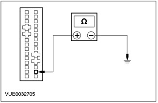
2Measure the resistance between the parking assist module (brown) circuit pin 16, harness side, C2100a and ground. |
|
• Is the resistance less than 5 ohms? |
|
|
→ Yes |
|
|
Go to A5. |
|
|
→ No |
|
|
CHECK and REPAIR the circuit between the parking assist module circuit C2100a pin 16 (brown) harness side and ground. If the circuit tests OK, INSTALL a new parking assist module. CHECK the system for proper operation. |
|
|
A4: CHECK PARKING ASSIST MODULE GROUND CIRCUIT |
|
|
1Enter the OFF position. |
|
|
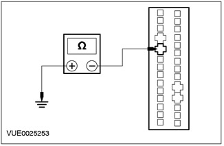
2Measure the resistance between the parking assist module (brown) circuit pin 10, harness side, C2100a and ground. |
|
• Is the resistance less than 5 ohms? |
|
|
→ Yes |
|
|
Go to A5. |
|
|
→ No |
|
|
CHECK and REPAIR the circuit between the parking assist module circuit C2100a pin 10 (brown) harness side and ground. If the circuit tests OK, INSTALL a new parking assist module. CHECK the system for proper operation. |
|
|
A5: CHECK PARKING ASSIST SYSTEM DISPLAY AND SPEAKER CIRCUIT (GRAY) FOR OPEN |
|
|
1Enter the OFF position. |
|
|
2Disconnect Parking Assist Display and Speaker - C2102. |
|
|
3Disconnect Parking Assist Module - C2100a. |
|
|
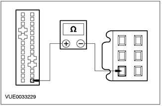
4Measure the resistance between pin 15 C2100a of the parking assist module (gray) circuit, harness side and pin 1 C2102 of the parking assist display and speaker assembly (gray) circuit, harness side. |
|
• Is the resistance less than 5 ohms? |
|
|
→ Yes |
|
|
Go to A6. |
|
|
→ No |
|
|
REPAIR the circuit between the parking assist module pin 15 C2100a of the gray circuit, harness side, and the parking assist display and speaker assembly pin 1 C2102 of the gray circuit, harness side. If the circuit tests OK, INSTALL a new parking assist display and speaker. CHECK the system for proper operation. |
|
|
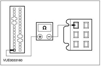
A6: CHECK PARKING ASSIST DISPLAY AND SPEAKER CIRCUIT (BLUE) FOR OPEN |
|
|
1Measure the resistance between pin 1 C2100a of the parking assist module circuit (blue) harness side and pin 3 C2102 of the parking assist display and speaker unit circuit (blue) harness side. |
|
• Is the resistance less than 5 ohms? |
|
|
→ Yes |
|
|
Go to A7. |
|
|
→ No |
|
|
REPAIR the circuit between the parking assist module pin 1 C2100a circuit (blue) harness side and the parking assist display and speaker assembly pin 3 C2102 circuit (blue) harness side. If the circuit tests OK, INSTALL a new parking assist display and speaker. CHECK the system for proper operation. |
|
|
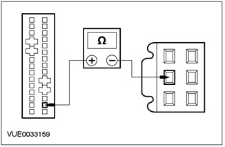
A7: CHECK PARKING ASSIST SYSTEM DISPLAY AND SPEAKER CIRCUIT (BROWN) FOR OPEN |
|
|
1Measure the resistance between pin 16 of the parking assist module C2100a of the wiring harness side circuit (brown) and pin 2 of the parking assist display and speaker assembly C2102 of the wiring harness side circuit (brown). |
|
• Is the resistance less than 5 ohms? |
|
|
→ Yes |
|
|
Go to A8. |
|
|
→ No |
|
|
REPAIR the circuit between the parking assist module (brown) circuit pin 16 C2100a, harness side, and the parking assist display and speaker assembly (brown) circuit pin 2 C2102, harness side. If the circuit tests OK, INSTALL a new parking assist display and speaker. CHECK the system for proper operation. |
|
|
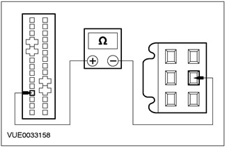
A8: CHECK PARKING ASSIST SYSTEM DISPLAY AND SPEAKER CIRCUIT (GREEN) FOR OPEN |
|
|
1Measure the resistance between pin 4 C2100a of the parking assist module (green) harness side circuit and pin 5 C2102 of the parking assist display and speaker assembly (green) harness side circuit. |
|
• Is the resistance less than 5 ohms? |
|
|
→ Yes |
|
|
Go to A9. |
|
|
→ No |
|
|
REPAIR the circuit between the parking assist module (green) harness side circuit pin 4 C2100a and the parking assist display and speaker assembly (green) harness side circuit pin 5 C2102. If the circuit tests OK, INSTALL a new parking assist display and speaker. CHECK the system for proper operation. |
|
|
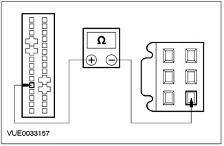
A9: CHECK PARKING ASSIST SYSTEM DISPLAY AND SPEAKER CIRCUIT (YELLOW) FOR OPEN |
|
|
1Measure the resistance between pin 5 C2100a of the parking assist module circuit (yellow) harness side and pin 4 C2102 of the parking assist display and speaker assembly circuit (yellow) harness side. |
|
• Is the resistance less than 5 ohms? |
|
|
→ Yes |
|
|
Go to A10. |
|
|
→ No |
|
|
REPAIR the circuit between the parking assist module (yellow) circuit pin 5 C2100a, harness side, and the parking assist display and speaker assembly (yellow) circuit pin 4 C2102, harness side. If the circuit tests OK, INSTALL a new parking assist display and speaker. CHECK the system for proper operation. |
|
|
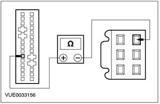
A10: CHECK PARKING ASSIST SYSTEM DISPLAY AND SPEAKER (WHITE) CIRCUIT FOR OPEN |
|
|
1Measure the resistance between pin 6 C2100a of the parking assist module circuit (white) harness side and pin 6 C2102 of the parking assist display and speaker unit circuit (white) harness side. |
|
• Is the resistance less than 5 ohms? |
|
|
→ Yes |
|
|
Go to A11. |
|
|
→ No |
|
|
REPAIR the circuit between the parking assist module (white) circuit pin 6 C2100a, harness side and the parking assist display and speaker assembly (white) circuit pin 6 C2102, harness side. If the circuit tests OK, INSTALL a new parking assist display and speaker. CHECK the system for proper operation. |
|
|
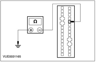
A11: CHECK PARKING AID MODULE FUSE LINK CIRCUIT FOR SHORT TO GROUND" |
|
|
1Disconnect the Parking Aid Module Fuse. |
|
|
2Measure the resistance between the parking assist module (pink) circuit pin 24 C2100a on the wiring harness side and ground. |
|
• Is the resistance greater than 10,000 ohms? |
|
|
→ Yes |
|
|
Go to A12. |
|
|
→ No |
|
|
CHECK and REPAIR the circuit between the parking assist module circuit pin 24 C2100a (pink) on the harness side and ground. If the circuit is OK, INSTALL a new parking assist module fuse link. CHECK the system for proper operation. |
|
|
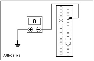
A12: CHECK PARKING AID MODULE FUSE LINK CIRCUIT FOR SHORT TO GROUND" |
|
|
1Measure the resistance between the parking assist module (pink) circuit pin 25 C2100a on the wiring harness side and ground. |
|
• Is the resistance greater than 10,000 ohms? |
|
|
→ Yes |
|
|
INSTALL a new parking aid module. CHECK the system for proper operation. |
|
|
→ No |
|
|
CHECK and REPAIR the circuit between the parking assist module circuit pin 25 C2100a (pink) harness side and ground. If the circuit is OK, INSTALL a new parking assist module fuse link. CHECK the system for proper operation. |
|
Element checks
Parking Assist Sensor Wiring Harness
NOTE: Refer to Electrical Schematics, Section 413-13, for diagrams and connection information.
NOTE: Check the parking assist system wiring harness for short to ground, short to battery, and damage.
1. Check the parking assist sensor wiring harness using the following table for the test lead installation order and expected values.
|
Parking Assist Sensor - C2105 |
Parking Assist Module - C2100b |
Expected value. |
Actions |
|
Pin 1 |
Pin 4 |
Less than 5 Ohm |
If the resistance is more than 5 ohms, CHECK and REPAIR the electrical circuit. If the electrical circuit is OK, INSTALL a new parking assist sensor. CHECK the system for proper operation |
|
Pin 2 |
Pin 10 |
Less than 5 Ohm |
If the resistance is more than 5 ohms, CHECK and REPAIR the electrical circuit. If the electrical circuit is OK, INSTALL a new parking assist sensor. CHECK the system for proper operation |
|
Pin 3 |
Pin 11 |
Less than 5 Ohm |
If the resistance is more than 5 ohms, CHECK and REPAIR the electrical circuit. If the electrical circuit is OK, INSTALL a new parking assist sensor. Check for proper system operation. |
|
Parking Assist Sensor - C2106 |
Parking Assist Module - C2100b |
Expected value. |
Actions |
|
Pin 1 |
Pin 3 |
Less than 5 Ohm |
If the resistance is more than 5 ohms, CHECK and REPAIR the electrical circuit. If the electrical circuit is OK, INSTALL a new parking assist sensor. Check for proper system operation. |
|
Pin 2 |
Pin 10 |
Less than 5 Ohm |
If the resistance is more than 5 ohms, CHECK and REPAIR the electrical circuit. If the electrical circuit is OK, INSTALL a new parking assist sensor. Check for proper system operation. |
|
Pin 3 |
Pin 11 |
Less than 5 Ohm |
If the resistance is more than 5 ohms, CHECK and REPAIR the electrical circuit. If the electrical circuit is OK, INSTALL a new parking assist sensor. Check for proper system operation. |
|
Parking Assist Sensor - C2107 |
Parking Assist Module - C2100b |
Expected value. |
Actions |
|
Pin 1 |
Pin 2 |
Less than 5 Ohm |
If the resistance is more than 5 ohms, CHECK and REPAIR the electrical circuit. If the electrical circuit is OK, INSTALL a new parking assist sensor. CHECK the system for proper operation. |
|
Pin 2 |
Pin 10 |
Less than 5 Ohm |
If the resistance is more than 5 ohms, CHECK and REPAIR the electrical circuit. If the electrical circuit is OK, INSTALL a new parking assist sensor. CHECK the system for proper operation |
|
Pin 3 |
Pin 11 |
Less than 5 Ohm |
If the resistance is more than 5 ohms, CHECK and REPAIR the electrical circuit. If the electrical circuit is OK, INSTALL a new parking assist sensor. CHECK the system for proper operation. |
|
Parking Assist Sensor - C2108 |
Parking Assist Module - C2100b |
Expected value. |
Actions |
|
Pin 1 |
Pin 1 |
Less than 5 Ohm |
If the resistance is more than 5 ohms, CHECK and REPAIR the electrical circuit. If the electrical circuit is OK, INSTALL a new parking assist sensor. Check for proper system operation. |
|
Pin 2 |
Pin 10 |
Less than 5 Ohm |
If the resistance is more than 5 ohms, CHECK and REPAIR the electrical circuit. If the electrical circuit is OK, INSTALL a new parking assist sensor. CHECK the system for proper operation. |
|
Pin 3 |
Pin 11 |
Less than 5 Ohm |
If the resistance is more than 5 ohms, CHECK and REPAIR the electrical circuit. If the electrical circuit is OK, INSTALL a new parking assist sensor. Check for proper system operation. |
(The original article is available on the website: www.fordbook.ru)