Special tool
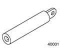 | Simulator, Airbag - Driver Airbag (Vehicles manufactured before 09/2002) 418-037 (40-001) |
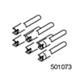 | Simulator, Airbag - Driver Airbag (Vehicles manufactured since 09/2002) 501-073 (40-016) |
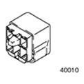 | Simulator, airbag - side airbag and buckle pretensioner (Vehicles manufactured before 09/2002) 418-138 (40-010) |
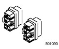 | Simulator, airbag - side airbag and buckle pretensioner (Vehicles manufactured since 09/2002) 501-093 (40-022) |
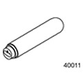 | Simulator, Airbag - Passenger Airbag 418-139 (40-011) |
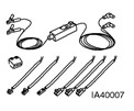 | Airbag/Pyrotechnic Pretensioner Test and Deployment Wire 418-S055 (40-007A) |
General equipment: WDS system.
Diagnosis of complaints received from the client, without "tough" DTCs/LFCs
WARNING: Before performing any work on the secondary restraint system and adjacent components, the backup battery must be discharged. Failure to follow this instruction may result in personal injury.
NOTE: Performing pinpoint tests when there are no DTCs/Tuning Lamp DTCs (DTC/LFC) leads to unreasonable replacement of elements of the airbag system and repeated repairs.
Check with the customer if a specific set of conditions is required for the failure to occur. If the client reports that an LFC code has been issued, but this code is not present when the car is received for repair, it is not possible to use diagnostics using pinpoint tests. Instruct the client how to count LFCs.
Diagnosis of complaints received from the client, if any "tough" DTCs/LFCs
WARNING: Do not use surrogate dummy airbags when performing work on the secondary restraint system. Use only the correct tool. Failure to follow these instructions may result in personal injury.
Most airbag system diagnostic procedures require the use of system deactivation and system reactivation procedures. These procedures require the module to be disconnected (to her) airbags and pretensioners from SRS, which eliminates the risk of airbag deployment during diagnostics.
Airbag simulators are required to perform diagnostics and test the airbag system. Do not short-circuit the airbag module connections with a 0 ohm lead wire. If a 0 ohm jumper wire is used to short the airbag module connections, an LFC will be issued and the airbag control module will set a DTC.
Deactivation
WARNING: Before performing any work on the secondary restraint system, the backup power source must be discharged. Wait at least one minute after disconnecting the wire "masses" battery. Failure to follow this instruction may result in personal injury.
1. Disconnect the wire "masses" battery. Refer to Section 414-01 for more information.
2. Wait at least one minute for the energy stored in the backup power source of the airbag control module to discharge.
WARNING: Place the module (And) airbags on a grounded workbench, decorative cover up. Failure to follow this instruction may result in personal injury.
3. Remove the driver's airbag module from the vehicle. For more information, refer to Driver Air Bag Module available in this section.
NOTE: Vehicles built before 10/2001: install 418-037. Vehicles manufactured since 10/2001: install 501-073.
4. Connect the driver's airbag dummy to the extra wiring harness in place of the driver's airbag module at the top of the steering column.
5. Disconnect the electrical connector (s) passenger airbag module. For more information, refer to Passenger Airbag Module available in this section.
6. Connect the passenger airbag dummy to the wiring harness in place of the passenger airbag module.
7. Disconnect the wiring harness electrical connector located on the floor under the driver's seat.
8. Instead of the side airbag module and seat belt pretensioner, connect a dummy airbag to the wiring harness electrical connector located on the floor under the driver's seat.
9. Disconnect the electrical harness connector located on the floor under the passenger seat.
NOTE: Vehicles built prior to 10/2001: install 418-138. Vehicles manufactured since 10.2001: install 501-093.
10. In place of the side airbag and seat belt pretensioner, connect a dummy airbag to the electrical harness connector located on the floor under the passenger seat.
11. Connect the wire "masses" battery. Refer to Section 414-01 for more information.
Reactivation
WARNING: When reactivated, the airbag dummy must be removed and the airbag modules must be reconnected to prevent the airbag from not deploying in the event of a collision. Failure to follow this instruction may result in personal injury.
1. Disconnect the wire "masses" battery. Refer to Section 414-01 for more information.
2. Wait at least one minute for the energy stored in the backup power source of the airbag control module to discharge.
3. Remove the driver's airbag simulator from the wiring harness at the top of the steering column.
4. Connect and install the driver's airbag module. For more information, refer to Driver Air Bag Module available in this section.
5. Remove the passenger airbag dummy from the passenger airbag harness.
6. Connect and install the passenger airbag module. For more information, refer to Passenger Airbag Module available in this section.
7. Remove the airbag dummy from the electrical harness connector located under the driver's seat.
8. Dock the electrical harness connector located under the driver's seat.
9. Remove the airbag dummy from the electrical harness connector located under the passenger seat.
10. Dock the electrical harness connector located under the passenger seat.
11. Connect the wire "masses" to the battery. Refer to Section 414-01 for more information.
12. Check the correct operation of the system.
Glossary
Airbag simulator
Airbag simulators are used to simulate the connections of an airbag module to the system.
Deactivate system
To deactivate a system means to perform a deactivation procedure. REFER to paragraph "Deactivation" in this section.
Check if the system is working properly
The airbag warning light comes on for approximately three seconds. If a malfunction is detected, the control lamp issues the corresponding flashing malfunction code.
Reactivate the system
To reactivate a system means to perform a reactivation procedure. REFER to paragraph "Reactivation" in this section.
Work principles
Function of the auxiliary restraint system (SRS)
The vehicle is equipped with a sensitive system operating on alternating current.
In the event of a significant full frontal or three-quarters frontal collision that exceeds a predetermined threshold, the front airbag inflates (And) driver and passenger safety (in the presence of).
In the event of a significant full-side impact exceeding a pre-set threshold, the driver or passenger side airbag will deploy (in the presence of). The airbag will only deploy in the event of a severe impact if the ignition key is in the RUN position.
Airbag control module
The airbag control module retains full control of the entire system, providing continuous system checks and full diagnostic capabilities. Non-volatile memory stores fault codes that can be uploaded to the WDS system via the data link connector (DLC).
In the event of a failure of the vehicle's power supply system during an accident, the airbag control module provides auxiliary power sufficient to deploy the airbag (ek) security, for at least 150 ms. The airbag control module discharges the backup power supply within 60 seconds after the wire is disconnected "masses" battery. This ensures that the secondary restraint system remains functional.
The airbag control module contains an electronic sensor (And) acceleration, which measures longitudinal acceleration and lateral acceleration (in vehicles equipped with side airbags) and ensures the transmission of both signals to the microcontroller, and the signal strength is proportional to the measured acceleration. When both of these sensors detect an impact greater than a predetermined threshold, the airbag control module initiates the airbag deployment circuit. The airbag control module also contains a protection sensor that will unlock the front airbags and buckle pretensioners in the event of a frontal collision, or only the buckle pretensioners in the event of a rear collision. The security sensor also prevents the airbags and buckle pretensioners from unintentionally deploying in the event of a malfunction in the electronic sensor (Oh) acceleration.
Vehicles equipped with a telematics system have a communication link from the airbag control module to the telematics control module. In the event of an airbag deployment, the telematics control module will automatically send an SOS signal. Refer to Section 419-05 for more information.
Airbag Control Module Configuration - Connecting to "weight" (Vehicles manufactured since 09/2002)
Airbag harness connections for LHD and RHD are the same. The airbag control module is internally configured for either LHD or RHD. Connection with "weight" on the configuration pin provides a signal confirming that the airbag control module is configured for RHD. Such a connection with "weight" not available in vehicles with LHD. The airbag control module continuously monitors this connection signal with "weight", and for an incorrect condition, the airbag control module sets a DTC.
Forward collision sensor (Vehicles manufactured since 09/2002)
The front impact sensor contains an acceleration sensor, a filter, an amplifier and a special integrated circuit for signal transmission. The sensor is mounted on the hood latch panel. The forward impact sensor sends a signal based on the severity of the impact to the airbag control module. The airbag control module compares the signal with the stored data and, if required, activates the front airbags and buckle pretensioners.
Side impact sensor
Side impact sensors are mounted on the side of the seat on both sides of the vehicle to facilitate remote detection of side impacts. Each side impact sensor contains a microprocessor that processes signals from the accelerometer built into the sensor. In the event of a collision that exceeds a predetermined threshold, the side impact sensor processes the side impact data and sends an airbag deployment request to the airbag control module. The airbag control module compares the received command with the data stored in the memory and deploys the side airbag on the side on which the deployment command was initiated. The airbag control module retains control of the side airbags.
Airbag warning lamp
Airbag warning lamp integrated in the instrument panel along with automatic disconnect detection circuit (ADD). The airbag warning light comes on for three seconds when the ignition is turned on. If the system self-test is successful, the control lamp goes out; if a malfunction is detected, the control lamp issues the corresponding flashing malfunction code.
The ADD circuit is provided to keep the airbag warning lamp on continuously if the airbag control module circuit is broken due to loss of power or connection to "weight". The airbag control module mounting bolts are part of the connection to the "weight".
Diagnosis of the SRS system can be performed using the data link connector (DLC) and a WDS system to determine the nature of the fault. Once the DTC has been determined, the appropriate corrective action can be selected using the Symptom Chart. For more information, refer to Diagnostic Instructions - Airbag and Pretensioner Supplemental Restraint System (SRS) available in this section.
Visitor comments