PINPOINT TEST A: NO COMMUNICATION TO MODULE
|
STATES |
DETAILS/RESULTS/ACTIONS |
|
A1: MAKE SURE THAT THE WDS/FDS 2000 IS COMMUNICATING VIA THE DATA LINK CONNECTOR (DLC) |
|
|
1 Select an alternate system to test the DLC. |
|
|
• Is WDS/FDS 2000 capable of communicating with the selected system? |
|
|
→ Yes |
|
|
Go to A2 |
|
|
→ No |
|
|
CHECK DLC. For more information, refer to Wiring Diagrams. |
|
|
A2: CHECKING THE AIR BAG LIGHT |
|
|
1 Drive the ON position. |
|
|
2 The airbag warning light should come on for three seconds when the ignition switch is ON, and then turn off. If a malfunction is present, the airbag warning lamp will flash after five seconds. |
|
|
• Does the airbag warning light work? |
|
|
→ Yes |
|
|
Go to A3 |
|
|
→ No |
|
|
CHECK instrument panel. For more information, refer to Wiring Diagrams. |
|
|
A3: DLC ELECTRICAL CIRCUIT CHECK |
|
|
WARNING: Wait at least one minute after disconnecting the battery ground wire before disconnecting any auxiliary restraint system connector. Failure to follow this instruction may result in injury. |
|
|
1 Enter the OFF position. |
|
|
2 Deactivate the assisted restraint system. |
|
|
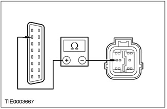
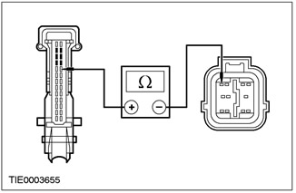
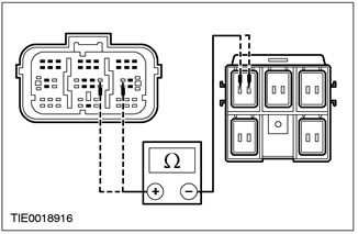
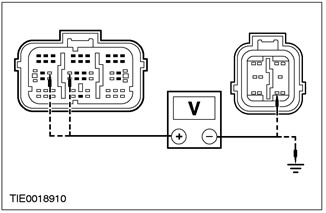
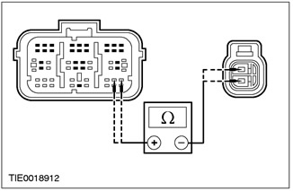
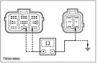
3 Disconnect the C424 airbag control module. |
|
|
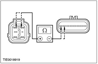
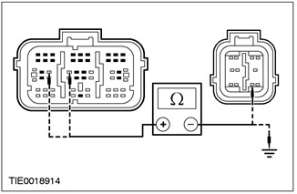
4 Measure the resistance between pin 7 C200 of the DLC connector, circuit 8-EE18 (white and black) and pin 7 C424 of the airbag control module, circuit 8-EE7 (white-red). |
|
• Is the resistance less than 5 ohms? |
|
|
→ Yes |
|
|
INSTALL a new airbag control module. REPEAT self-test, CLEAR DTCs. RE-ACTIVATE the system. |
|
|
→ No |
|
|
REPAIR circuit 8-EE18 (white and black) /8-EE7 (white-red). REPEAT self-test, CLEAR DTCs. RE-ACTIVATE the system. |
|
PINPOINT TEST B: DTC B1921: AIR BAG LIGHT GROUND CIRCUIT OPEN
|
STATES |
DETAILS/RESULTS/ACTIONS |
|
B1: CHECK AIR BAG MOUNTING |
|
|
WARNING: Wait at least one minute after disconnecting the battery ground wire before disconnecting any auxiliary restraint system connector. Failure to follow this instruction may result in injury. |
|
|
1 Deactivate the auxiliary restraint system. |
|
|
2 Remove the floor console. See Section 501-12 for more information. |
|
|
3 Check the mounting of the airbag control module. |
|
|
• Is the airbag control module properly installed, are all bolts tightened to the correct torque? |
|
|
→ Yes |
|
|
Navigate to B2 |
|
|
→ No |
|
|
LOCK the airbag control module. REPEAT self-test, CLEAR DTCs. RE-ACTIVATE the system. |
|
|
B2: GROUND CHECK OF AIR BAG MODULE HOUSING |
|
|
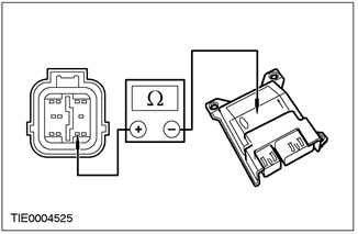
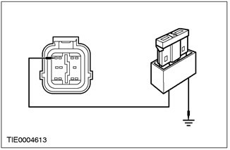
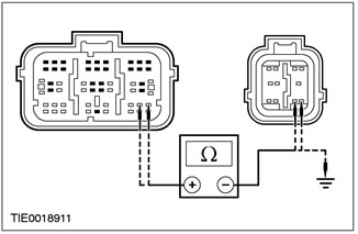
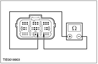
1 Disconnect the C424 airbag control module. |
|
|
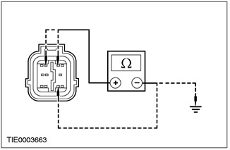
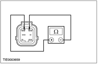
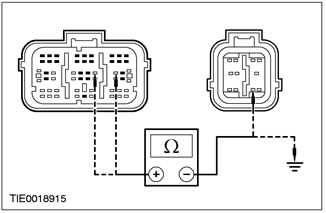
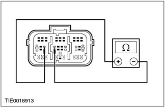
2 Measure the resistance between pin 9 C424 of the airbag control module, circuit 91-JA10 (black and red), on the wiring side, and the airbag control module housing. |
|
• Is the resistance less than 5 ohms? |
|
|
→ Yes |
|
|
REPEAT the self test. CLEAR DTCs. RE-ACTIVATE the system. |
|
|
→ No |
|
|
REMOVE the airbag control module. CLEAN airbag control module support (including bolts). INSTALL the airbag control module. REPEAT self-test, CLEAR DTCs. RE-ACTIVATE the system. |
|
PINPOINT TEST C: DTC B1318: BATTERY VOLTAGE LOW
|
STATES |
DETAILS/RESULTS/ACTIONS |
|
C1: BATTERY VOLTAGE CHECK |
|
|
1 Drive the ON position. |
|
|
2 Check the battery voltage with the ignition switch on. |
|
|
• Is the battery voltage over 9V? |
|
|
→ Yes |
|
|
Go to C2 |
|
|
→ No |
|
|
CHECK the battery and charging system. See Section 414-00 for more information. REPEAT the self test. CLEAR DTCs. |
|
|
C2: CHECK THE STATE OF THE FUSE. |
|
|
1 Enter the OFF position. |
|
|
2 Disconnect Fuse 60 (7.5 A). |
|
|
3CHECK Fuse 60 (7.5 A). |
|
|
4 Check fuse 60 (7.5 A). |
|
|
• Is the fuse or terminals corroded? |
|
|
→ Yes |
|
|
CLEAN terminals. INSTALL a new fuse 60 (7.5 A). REPEAT self-test, CLEAR DTCs. |
|
|
→ No |
|
|
Go to C3 |
|
|
C3: AIRBAG CONTROL MODULE ELECTRICAL CHECK |
|
|
WARNING: Wait at least one minute after disconnecting the battery ground wire before disconnecting any auxiliary restraint system connector. Failure to follow this instruction may result in injury. |
|
|
1 Deactivate the auxiliary restraint system. |
|
|
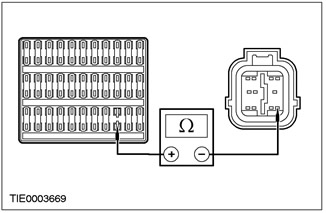
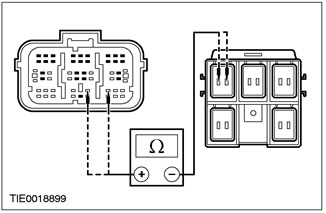
2 Disconnect the C424 airbag control module. |
|
|
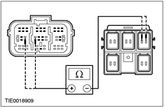
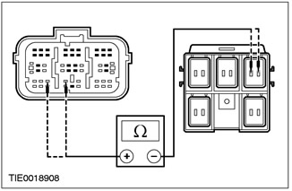
3 Measure resistance between fuse output 60 (7.5A) and pin 8 C424 of the airbag control module, circuit 15-JA10 (green-orange), from the side of the electrical wiring. |
|
• Is the resistance less than 5 ohms? |
|
|
→ Yes |
|
|
Go to C4 |
|
|
→ No |
|
|
CHECK the plug connector terminals for signs of corrosion or dirt. REPEAT the self test. CLEAR DTCs. RE-ACTIVATE the system. |
|
|
C4: AIR BAG MODULE GROUND CIRCUIT CHECK |
|
|
1 Measure the resistance between pin 9 C424 of the airbag control module, circuit 91-JA10 (black and red), and a grounding point on the A-pillar G41. |
|
• Is the resistance less than 2 ohms? |
|
|
→ Yes |
|
|
REPEAT self-test, CLEAR DTCs. RE-ACTIVATE the system. |
|
|
→ No |
|
|
CHECK the ground point on the G41 A-pillar of the airbag control module for tightness and corrosion. REPEAT self-test, CLEAR DTCs. RE-ACTIVATE the system. |
|
PINPOINT TEST D: DTC B1869: OPEN OR SHORT TO «MASS» ELECTRICAL CIRCUIT OF THE AIRBAG LAMP.
|
STATES |
DETAILS/RESULTS/ACTIONS |
|
D1: CHECK AIR BAG LAMP |
|
|
1 Drive the ON position. |
|
|
2Check the airbag warning light. |
|
|
• Is the airbag warning light on continuously? |
|
|
→ Yes |
|
|
Go to D2 |
|
|
→ No |
|
|
Go to D5 |
|
|
D2: AIR BAG LIGHT CIRCUIT CHECK |
|
|
WARNING: Wait at least one minute after disconnecting the battery ground wire before disconnecting any auxiliary restraint system connector. Failure to follow this instruction may result in injury. |
|
|
1 Enter the OFF position. |
|
|
2 Deactivate the assisted restraint system. |
|
|
3 Disconnect the C424 airbag control module. |
|
|
4 Disconnect the C809 instrument panel. |
|
|
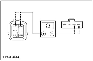
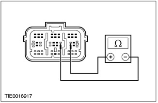
5 Measure the resistance between pin 22 C809 of instrument panel, circuit 91S-JA14 (black and green), and pin 4 C424 of the airbag control module, circuit 91S-JA14 (black and green), from the side of the electrical wiring. |
|
• Is the resistance less than 5 ohms? |
|
|
→ Yes |
|
|
Go to D3 |
|
|
→ No |
|
|
REPAIR circuit 91S-JA14 (black and green). REPEAT self-test, CLEAR DTCs. RE-ACTIVATE the system. |
|
|
D3: CHECKING THE FUNCTIONING OF THE AIR BAG LAMP |
|
|
1 Connect C809 instrument panel. |
|
|
2 Install fuse connection wire (7.5 A) between pin 4 C424 of the airbag control module, circuit 91S-JA14 (black and green), from the wiring side, and "ground". |
|
|
3Turn the ignition ON. |
|
• Is the airbag warning light on? |
|
|
→ Yes |
|
|
INSTALL a new automatic shutdown detection circuit/instrument panel printed circuit. REPEAT self-test, CLEAR DTCs. RE-ACTIVATE the system. |
|
|
→ No |
|
|
Go to D4. |
|
|
D4: FUNCTIONAL CHECK OF AIR BAG LAMP (CONTINUATION) |
|
|
1 Do not disconnect the fused connection wire (7.5 A) between pin 4 C424 of the airbag control module, circuit 91S-JA14 (black and green) and "mass". |
|

|
2 Disconnect the fused wire from ground. |
|
• Is the airbag warning light on? |
|
|
→ Yes |
|
|
INSTALL a new airbag control module. REPEAT self-test, CLEAR DTCs. RE-ACTIVATE the system. |
|
|
→ No |
|
|
REPEAT self-test, CLEAR DTCs. RE-ACTIVATE the system. |
|
|
D5: INSTRUMENT PANEL LIGHTS CHECK |
|
|
WARNING: Wait at least one minute after disconnecting the battery ground wire before disconnecting any auxiliary restraint system connector. Failure to follow this instruction may result in injury. |
|
|
NOTE: The airbag control module activates an audible warning when the airbag warning lamp malfunctions and there is another malfunction in the auxiliary restraint system (for example, an open circuit in the driver's airbag module). In all cases, REPAIR the airbag warning light first. |
|
|
1 Enter the OFF position. |
|
|
2 Deactivate the assisted restraint system. |
|
|
3 Drive the ON position. |
|
|
4 Check the indicator lamps on the instrument panel. |
|
|
• Do the control lamps come on when the ignition is turned to the ON position? |
|
|
→ Yes |
|
|
Go to D6 |
|
|
→ No |
|
|
CHECK instrument panel fuse. For more information, refer to Wiring Diagrams. |
|
|
D6: AIR BAG LIGHT CIRCUIT CHECK |
|
|
1 Enter the OFF position. |
|
|
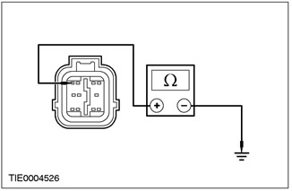
2 Disconnect the C424 airbag control module. |
|
|
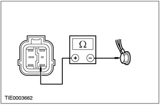
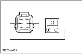
3 Measure the resistance between C424 pin 4 of the airbag control module, circuit 91S-JA14 (black and green), from the wiring harness side, and ground. |
|
• Is the resistance greater than 10,000 ohms? |
|
|
→ Yes |
|
|
CHECK the airbag indicator LED/bulb. REPEAT self-test, CLEAR DTCs. RE-ACTIVATE the system. |
|
|
→ No |
|
|
REPAIR circuit 91S-JA14 (black and green). REPEAT self-test, CLEAR DTCs. RE-ACTIVATE the system. |
|
PINPOINT TEST E: DTC B1870: AIR BAG LAMP ELECTRICAL CIRCUIT SHORT TO BATTERY
|
STATES |
DETAILS/RESULTS/ACTIONS |
|
WARNING: Wait at least one minute after disconnecting the battery ground wire before disconnecting any auxiliary restraint system connector. Failure to follow this instruction may result in injury. |
|
|
E1: AIR BAG LAMP ELECTRICAL CIRCUIT CHECK |
|
|
1 Deactivate the auxiliary restraint system. |
|
|
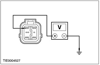
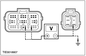
2 Disconnect the C424 airbag control module. |
|
|
3 Disconnect the C809 instrument panel. |
|
|
4 Drive the ON position. |
|
|
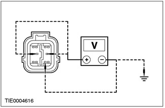
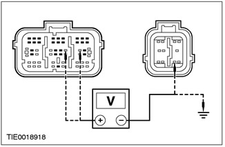
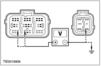
5 Measure the voltage between C424 pin 4 of the airbag control module, circuit 91S-JA14 (black and green), from the wiring harness side, and ground. |
|
• Is voltage being registered? |
|
|
→ Yes |
|
|
REPAIR circuit 91S-JA14 (black and green) and 15-JA10 (green-orange) or 91S-JA14A (black and green). REPEAT self-test, CLEAR DTCs. RE-ACTIVATE the system. |
|
|
→ No |
|
|
CHECK instrument panel. See Section 413-01 for more information. REPEAT self-test, CLEAR DTCs. RE-ACTIVATE the system. |
|
PINPOINT TEST F: DTC B1887: DRIVER AIR BAG ELECTRICAL CIRCUIT SHORT TO «MASS»
|
STATES |
DETAILS/RESULTS/ACTIONS |
|
WARNING: Wait at least one minute after disconnecting the battery ground wire before disconnecting any auxiliary restraint system connector. Failure to follow this instruction may result in injury. |
|
|
F1: DRIVER AIRBAG CIRCUIT TEST |
|
|
1 Deactivate the auxiliary restraint system. |
|
|
2 Drive the ON position. |
|
|
3 Perform a self-test with installed simulators. |
|
|
• Is the system functioning correctly? |
|
|
→ Yes |
|
|
Go to F2 |
|
|
→ No |
|
|
Go to F3 |
|
|
F2: DRIVER AIR BAG MODULE CHECK |
|
|
WARNING: Do not continue with this test if you are not using WDS/FDS 2000. Failure to follow this instruction could result in personal injury. |
|
|
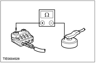
1 Connect test/initiate wire 40-007-01 to driver airbag module. |
|
|
2 Select the DMM option in WDS/FDS 2000. |
|
|
3 Connect test/trigger wire to WDS/FDS 2000. |
|
|
4 Measure the resistance between each of the pins and the airbag module housing. |
|
• Is the resistance greater than 10,000 ohms? |
|
|
→ Yes |
|
|
REPEAT self-test, CLEAR DTCs. RE-ACTIVATE the system. |
|
|
→ No |
|
|
INSTALL a new driver airbag module. REPEAT self-test, CLEAR DTCs. RE-ACTIVATE the system. |
|
|
F3: CHECK AUXILIARY AIR BAG HARNESS FOR SHORT TO " GROUND " |
|
|
1 Enter the OFF position. |
|
|
2 Disconnect the C424 airbag control module. |
|
|
3 Disconnect the Dummy Driver Air Bag Module. |
|
|
4 Measure the resistance between: - pin 2 C424 of the airbag control module, circuit 15S-JA8 (green-red), and pin 9, electrical circuit 91-JA10 (black and red), from the wiring side; And - pin 2 C424 of the airbag control module, circuit 15S-JA8 (green-red), from the wiring side, and "ground"; And - pin 3 C424 of the airbag control module, circuit 91S-JA8 (black-orange), and pin 9, electrical circuit 91-JA10 (black and red), from the wiring side; And - pin 3 C424 of the airbag control module, circuit 91S-JA8 (black-orange), from the wiring side, and "ground". |
|

|
5 While checking, turn the steering wheel between the lock positions while noting the gauge reading. |
|
• Is the resistance greater than 10,000 ohms in all cases? |
|
|
→ Yes |
|
|
REPEAT self-test, CLEAR DTCs. RE-ACTIVATE the system. |
|
|
→ No |
|
|
Go to F4 |
|
|
F4: CHECK CLOCK SPRING ELECTRICAL CIRCUIT FOR SHORT TO " GROUND " |
|
|
1 Disconnect the C920 driver airbag module harness. |
|
|
2 Measure the resistance between: - pin 2 C424 of the airbag control module, circuit 15S-JA8 (green-red), and pin 9, electrical circuit 91-JA10 (black and red), from the wiring side; And - pin 2 C424 of the airbag control module, circuit 15S-JA8 (green-red), from the wiring side, and "ground"; And - pin 3 C424 of the airbag control module, circuit 91S-JA8 (black-orange), and pin 9, electrical circuit 91-JA10 (black and red), from the wiring side; And - pin 3 C424 of the airbag control module, circuit 91S-JA8 (black-orange), from the wiring side, and "ground". |
|

|
3 While checking, turn the steering wheel between the lock positions while noting the gauge reading. |
|
• Is the resistance greater than 10,000 ohms? |
|
|
→ Yes |
|
|
INSTALL a new airbag harness. REPEAT self-test, CLEAR DTCs. RE-ACTIVATE the system. |
|
|
→ No |
|
|
Go to F5 |
|
|
F5: CHECK DRIVER AIR BAG MODULE ELECTRICAL CIRCUIT FOR SHORT TO « GROUND » |
|
|
1 Disconnect the C896 clock spring. |
|
|
2 Measure the resistance between: - pin 2 C424 of the airbag control module, circuit 15S-JA8 (green-red), and pin 9, electrical circuit 91-JA10 (black and red), from the wiring side; And - pin 2 C424 of the airbag control module, circuit 15S-JA8 (green-red), from the wiring side, and "ground"; And - pin 3 C424 of the airbag control module, circuit 91S-JA8 (black-orange), and pin 9, electrical circuit 91-JA10 (black and red), from the wiring side; And - pin 3 C424 of the airbag control module, circuit 91S-JA8 (black-orange), from the wiring side, and "ground". |
|
• Is the resistance greater than 10,000 ohms in all cases? |
|
|
→ Yes |
|
|
INSTALL a new clock spring. For more information refer to Clock Spring available in this section. REPEAT self-test, CLEAR DTCs. RE-ACTIVATE the system. |
|
|
→ No |
|
|
REPAIR circuit 15S-JA8 (green-red) or 91S-JA8 (black and orange) and 91-JA10 (black and red). REPEAT self-test, CLEAR DTCs. RE-ACTIVATE the system. |
|
PINPOINT TEST G: DTC B1916: DRIVER AIR BAG ELECTRICAL CIRCUIT SHORT TO BATTERY
|
STATES |
DETAILS/RESULTS/ACTIONS |
|
G1: CHECK AUXILIARY AIR BAG HARNESS FOR SHORT TO + BATTERY |
|
|
WARNING: Wait at least one minute after disconnecting the battery ground wire before disconnecting any auxiliary restraint system connector. Failure to follow this instruction may result in injury. |
|
|
1 Deactivate the auxiliary restraint system. |
|
|
2 Visually inspect the driver's airbag accessory harness for damage. |
|
|
3 Disconnect the Dummy Driver Air Bag Module. |
|
|
4 Drive the ON position. |
|

|
5 Measure the voltage between: - pin 2 C424 of the airbag control module, circuit 15S-JA8 (green-red), and pin 9, electrical circuit 91-JA10 (black and red), from the wiring side; And - pin 2 C424 of the airbag control module, circuit 15S-JA8 (green-red), from the wiring side, and "ground"; - pin 3 C424 of the airbag control module, circuit 91S-JA8 (black-orange), and pin 9, electrical circuit 91-JA10 (black and red), from the wiring side; And - pin 3 C424 of the airbag control module, circuit 91S-JA8 (black-orange), from the wiring side, and "ground". |
|
• Is voltage being registered? |
|
|
→ Yes |
|
|
Go to G2 |
|
|
→ No |
|
|
CONNECT dummy driver airbag module and airbag control module. REPEAT self-test, CLEAR DTCs. RE-ACTIVATE the system. |
|
|
G2: CHECK CLOCK SPRING ELECTRICAL CIRCUIT FOR SHORT TO + BATTERY |
|
|
1 Enter the OFF position. |
|
|
2 Disconnect the C920 driver airbag harness. |
|
|
3 Drive the ON position. |
|
|
4 Measure the voltage between: - pin 2 C424 of the airbag control module, circuit 15S-JA8 (green-red), and pin 9, electrical circuit 91-JA10 (black and red), from the wiring side; And - pin 2 C424 of the airbag control module, circuit 15S-JA8 (green-red), from the wiring side, and "ground"; And - pin 3 C424 of the airbag control module, circuit 91S-JA8 (black-orange), and pin 9, electrical circuit 91-JA10 (black and red), from the wiring side; And - pin 3 C424 of the airbag control module, circuit 91S-JA8 (black-orange), from the wiring side, and "ground". |
|

|
5 While checking, turn the steering wheel between the lock positions while noting the gauge reading. |
|
• Is voltage being registered? |
|
|
→ Yes |
|
|
Go to G3 |
|
|
→ No |
|
|
INSTALL a new airbag harness. REPEAT self-test, CLEAR DTCs. RE-ACTIVATE the system. |
|
|
G3: CHECK AIR BAG HARNESS FOR SHORT TO "+ " BATTERY |
|
|
1 Enter the OFF position. |
|
|
2 Disconnect the C896 clock spring. |
|
|
3 Drive the ON position. |
|

|
4 Measure the voltage between: - pin 2 C424 of the airbag control module, circuit 15S-JA8 (green-red), and pin 9, electrical circuit 91-JA10 (black and red), from the wiring side; And - pin 2 C424 of the airbag control module, circuit 15S-JA8 (green-red), from the wiring side, and "ground"; And - pin 3 C424 of the airbag control module, circuit 91S-JA8 (black-orange), and pin 9, electrical circuit 91-JA10 (black and red), from the wiring side; And - pin 3 C424 of the airbag control module, circuit 91S-JA8 (black-orange), from the wiring side, and "ground". |
|
• Is voltage being registered? |
|
|
→ Yes |
|
|
REPAIR circuit 15S-JA8 (green-red) or 91S-JA8 (black and orange) and 15-JA10 (green-orange) or 91S-JA14A (black and green). REPEAT self-test, CLEAR DTCs. RE-ACTIVATE the system. |
|
|
→ No |
|
|
INSTALL a new clock spring. For more information refer to Clock Spring available in this section. REPEAT self-test, CLEAR DTCs. RE-ACTIVATE the system. |
|
PINPOINT TEST H: DTC B1932: DRIVER AIR BAG CIRCUIT OPEN OR HIGH RESISTANCE
|
STATES |
DETAILS/RESULTS/ACTIONS |
|
H1: DRIVER AIR BAG MODULE ELECTRICAL RESISTANCE CHECK |
|
|
WARNING: Wait at least one minute after disconnecting the battery ground wire before disconnecting any auxiliary restraint system connector. Failure to follow this instruction may result in injury. |
|
|
1 Deactivate the auxiliary restraint system. |
|
|
2 Drive the ON position. |
|
|
3 Perform a self-test with installed simulators. |
|
|
• Is the system functioning correctly? |
|
|
→ Yes |
|
|
Go to H2 |
|
|
→ No |
|
|
Go to H3 |
|
|
H2: CHECK DRIVER AIR BAG MODULE IGNITOR RESISTANCE |
|
|
WARNING: Do not continue with this test if you are not using WDS/FDS 2000. Failure to follow this instruction could result in personal injury. |
|
|
1 Connect test/initiate wire 40-007-01 to driver airbag module. |
|
|
2 Select the DMM option in WDS/FDS 2000. |
|
|
3 Connect test/trigger wire to WDS/FDS 2000. |
|
|
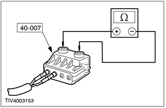
4 Measure the resistance of the airbag module ignition circuit. |
|
• Is the resistance between 2 and 3 ohms? |
|
|
→ Yes |
|
|
REPEAT self-test, CLEAR DTCs. RE-ACTIVATE the system. |
|
|
→ No |
|
|
INSTALL a new driver airbag module. REPEAT self-test, CLEAR DTCs. RE-ACTIVATE the system. |
|
|
H3: CHECK DRIVER'S AIR BAG MODULE AUXILIARY WIRING HARNESS FOR OPEN OR HIGH RESISTANCE CIRCUIT |
|
|
1 Enter the OFF position. |
|
|
2 Disconnect the C920 driver airbag module harness. |
|
|
3 Measure the resistance between: - pin 2 C424 of the airbag control module, circuit 15S-JA8 (green-red), wiring side, and pin 4 C920 clock spring, circuit 15S-JA8 (green-red), from the side of the element; And - pin 3 C424 of the airbag control module, circuit 91S-JA8 (black-orange), wiring side, and pin 3 C920 clock spring, circuit 91S-KA8 (black-orange), from the side of the element. - During the test, turn the steering wheel between the lock positions, noting the gauge reading. |
|
• Is the resistance always less than 5 ohms? |
|
|
→ Yes |
|
|
INSTALL a new driver airbag accessory harness REPEAT self-test, CLEAR DTCs. RE-ACTIVATE the system. |
|
|
→ No |
|
|
Move to H4 |
|
|
H4: CHECK CLOCK SPRING ELECTRICAL CIRCUIT FOR OPEN OR HIGH RESISTANCE |
|
|
1 Disconnect the C896 clock spring. |
|
|
2 Measure the resistance between: - pin 2 C424 of the airbag control module, circuit 15S-JA8 (green-red), and pin 8 C896 clock spring, circuit 15S-JA8 (green-red), from the wiring side; And - pin 3 C424 of the airbag control module, circuit 91S-JA8 (black-orange), and pin 7 C896 clock spring, circuit 91S-JA8 (black-orange), from the side of the electrical wiring. |
|
• Is the resistance always less than 5 ohms? |
|
|
→ Yes |
|
|
Install a new clock spring. For more information refer to Clock Spring available in this section. REPEAT self-test, CLEAR DTCs. RE-ACTIVATE the system. |
|
|
→ No |
|
|
REPAIR circuit 15S-JA8 (green-red) or 91S-JA8 (black and orange). REPEAT self-test, CLEAR DTCs. RE-ACTIVATE the system. |
|
PINPOINT TEST I: DTC B1934: DRIVER AIR BAG CIRCUIT LOW RESISTANCE
|
STATES |
DETAILS/RESULTS/ACTIONS |
|
I1: DRIVER AIR BAG MODULE ELECTRICAL RESISTANCE CHECK |
|
|
WARNING: Wait at least one minute after disconnecting the battery ground wire before disconnecting any auxiliary restraint system connector. Failure to follow this instruction may result in injury. |
|
|
1 Deactivate the auxiliary restraint system. |
|
|
2 Drive the ON position. |
|
|
3 Perform a self-test with installed simulators. |
|
|
• Is the system functioning correctly? |
|
|
→ Yes |
|
|
Go to I2 |
|
|
→ No |
|
|
Go to I3 |
|
|
I2: DRIVER AIR BAG MODULE IGNITOR ELECTRICAL RESISTANCE CHECK |
|
|
WARNING: Do not continue with this test if you are not using WDS/FDS 2000. Failure to follow this instruction could result in personal injury. |
|
|
1 Connect test/initiate wire 40-007-01 to driver airbag module. |
|
|
2 Select the DMM option in WDS/FDS 2000. |
|
|
3 Connect test/trigger wire to WDS/FDS 2000. |
|

|
4 Measure the resistance of the airbag module ignition circuit. |
|
• Is the resistance between 2 and 3 ohms? |
|
|
→ Yes |
|
|
REPEAT self-test, CLEAR DTCs. RE-ACTIVATE the system. |
|
|
→ No |
|
|
INSTALL a new driver airbag module. REPEAT self-test, CLEAR DTCs. RE-ACTIVATE the system. |
|
|
I3: CHECK AIR BAG HARNESS FOR LOW RESISTANCE |
|
|
1 Enter the OFF position. |
|
|
2 Disconnect the C920 airbag module wiring harness. |
|

|
3 Measure the resistance between C424 pin 2 of the airbag control module, circuit 15S-JA8 (green-red), and pin 3, electric circuit 91S-JA8 (black-orange), from the side of the electrical wiring. - During the test, turn the steering wheel between the lock positions, noting the gauge reading. |
|
• Is the resistance greater than 10,000 ohms? |
|
|
→ Yes |
|
|
INSTALL a new airbag harness. REPEAT self-test, CLEAR DTCs. RE-ACTIVATE the system. |
|
|
→ No |
|
|
Go to I4 |
|
|
I4: CHECK CLOCK SPRING ELECTRICAL CIRCUIT FOR LOW RESISTANCE |
|
|
1 Disconnect the C896 clock spring. |
|
|
2 Measure the resistance between C424 pin 2 of the airbag control module, circuit 15S-JA8 (green-red), and pin 3, electric circuit 91S-JA8 (black-orange), from the side of the electrical wiring. |
|
• Is the resistance greater than 10,000 ohms? |
|
|
→ Yes |
|
|
INSTALL a new clock spring. For more information refer to Clock Spring available in this section. REPEAT self-test, CLEAR DTCs. RE-ACTIVATE the system. |
|
|
→ No |
|
|
REPAIR circuit 15S-JA8 (green-red) and 91S-JA8 (black and orange). REPEAT self-test, CLEAR DTCs. RE-ACTIVATE the system. |
|
PINPOINT TEST J: DTC B1888: PASSENGER AIR BAG ELECTRICAL CIRCUIT SHORT TO «MASS»
|
STATES |
DETAILS/RESULTS/ACTIONS |
|
J1: PASSENGER AIR BAG CIRCUIT CHECK |
|
|
WARNING: Wait at least one minute after disconnecting the battery ground wire before disconnecting any auxiliary restraint system connector. Failure to follow this instruction may result in injury. |
|
|
1 Deactivate the auxiliary restraint system. |
|
|
2 Drive the ON position. |
|
|
3 Perform a self-test with installed simulators. |
|
|
• Is the system functioning correctly? |
|
|
→ Yes |
|
|
Go to J2 |
|
|
→ No |
|
|
Go to J3 |
|
|
J2: PASSENGER AIRBAG MODULE CHECK |
|
|
WARNING: Do not continue with this test if you are not using WDS/FDS 2000. Failure to follow this instruction could result in personal injury. |
|
|
1 Connect test/initiate wire 40-007-01 to driver airbag module. |
|
|
2 Select the DMM option in WDS/FDS 2000. |
|
|
3 Connect test/trigger wire to WDS/FDS 2000. |
|

|
4 Measure the resistance between each of the pins and the airbag module housing. |
|
• Is the resistance greater than 10,000 ohms? |
|
|
→ Yes |
|
|
REPEAT self-test, CLEAR DTCs. RE-ACTIVATE the system. |
|
|
→ No |
|
|
INSTALL a new passenger airbag module. REPEAT self-test, CLEAR DTCs. RE-ACTIVATE the system. |
|
|
J3: CHECK PASSENGER AIR BAG CIRCUIT FOR SHORT TO " GROUND " |
|
|
1 Enter the OFF position. |
|
|
2 Disconnect the C424 airbag control module. |
|

|
3 Measure the resistance between: - pin 5 C424 of the airbag control module, circuit 15S-JA11 (green-white), and pin 9, electrical circuit 91-JA10 (black and red), from the wiring side; And - pin 5 C424 of the airbag control module, circuit 15S-JA11 (green-white), from the wiring side, and "ground"; And - pin 6 C424 of the airbag control module, circuit 91S-JA11 (black and white), and pin 9, electrical circuit 91-JA10 (black and red), from the wiring side; And - pin 6 C424 of the airbag control module, circuit 91S-JA11 (black and white), from the wiring side, and "ground". |
|
• Is the resistance greater than 10,000 ohms in all cases? |
|
|
→ Yes |
|
|
REPEAT self-test, CLEAR DTCs. RE-ACTIVATE the system. |
|
|
→ No |
|
|
REPAIR circuit 15S-JA11 (green and white) or 91S-JA11 (black and white) and 91-JA10 (black and red). REPEAT self-test, CLEAR DTCs. RE-ACTIVATE the system. |
|
PINPOINT TEST K: DTC B1925: PASSENGER AIR BAG ELECTRICAL CIRCUIT SHORT TO BATTERY
|
STATES |
DETAILS/RESULTS/ACTIONS |
|
K1: CHECK PASSENGER AIR BAG CIRCUIT FOR SHORT TO BATTERY |
|
|
WARNING: Wait at least one minute after disconnecting the battery ground wire before disconnecting any auxiliary restraint system connector. Failure to follow this instruction may result in injury. |
|
|
1 Deactivate the auxiliary restraint system. |
|
|
2 Visually inspect the passenger airbag harness for damage. |
|
|
3 Disconnect the Dummy Passenger Airbag Module. |
|
|
4 Drive the ON position. |
|
|
5 Measure the voltage between: - pin 5 C424 of the airbag control module, circuit 15S-JA11 (green-white), and pin 9, electrical circuit 91-JA10 (black and red), from the wiring side; And - pin 5 C424 of the airbag control module, circuit 15S-JA11 (green-white), from the wiring side, and "ground"; And - pin 6 C424 of the airbag control module, circuit 91S-JA11 (black and white), and pin 9, electrical circuit 91-JA10 (black and red), from the wiring side; And - pin 6 C424 of the airbag control module, circuit 91S-JA11 (black and white), from the wiring side, and "ground". |
|
• Is voltage being registered? |
|
|
→ Yes |
|
|
REPAIR circuit 15S-JA11 (green and white) or 91S-JA11 (black and white) and 15-JA10 (green-orange) or 91S-JA14A (black and green). REPEAT self-test, CLEAR DTCs. RE-ACTIVATE the system. |
|
|
→ No |
|
|
CONNECT dummy passenger airbag module and airbag control module. REPEAT self-test, CLEAR DTCs. RE-ACTIVATE the system. |
|
PINPOINT TEST L: DTC B1933: PASSENGER AIR BAG CIRCUIT OPEN OR HIGH RESISTANCE
|
STATES |
DETAILS/RESULTS/ACTIONS |
|
L1: PASSENGER AIR BAG MODULE ELECTRICAL RESISTANCE CHECK |
|
|
WARNING: Wait at least one minute after disconnecting the battery ground wire before disconnecting any auxiliary restraint system connector. Failure to follow this instruction may result in injury. |
|
|
1 Deactivate the auxiliary restraint system. |
|
|
2 Drive the ON position. |
|
|
3 Perform a self-test with installed simulators. |
|
|
• Is the system functioning correctly? |
|
|
→ Yes |
|
|
Go to L2 |
|
|
→ No |
|
|
REPAIR circuit 15S-JA11 (green and white) or 91S-JA11 (black and white). REPEAT self-test, CLEAR DTCs. RE-ACTIVATE the system. |
|
|
L2: PASSENGER AIR BAG MODULE IGNITOR ELECTRICAL RESISTANCE CHECK |
|
|
WARNING: Do not continue with this test if you are not using WDS/FDS 2000. Failure to follow this instruction could result in personal injury. |
|
|
1 Connect test/initiate wire 40-007-01 to passenger airbag module. |
|
|
2 Select the DMM option in WDS/FDS 2000. |
|
|
3 Connect test/trigger wire to WDS/FDS 2000. |
|

|
4 Measure the resistance of the airbag module ignition circuit. |
|
• Is the resistance between 2 and 3 ohms? |
|
|
→ Yes |
|
|
REPEAT self-test, CLEAR DTCs. RE-ACTIVATE the system. |
|
|
→ No |
|
|
INSTALL a new passenger airbag module. REPEAT self-test, CLEAR DTCs. RE-ACTIVATE the system. |
|
PINPOINT TEST M: DTC B1935: PASSENGER AIR BAG CIRCUIT RESISTANCE LOW
|
STATES |
DETAILS/RESULTS/ACTIONS |
|
M1: PASSENGER AIR BAG MODULE ELECTRICAL RESISTANCE CHECK |
|
|
WARNING: Wait at least one minute after disconnecting the battery ground wire before disconnecting any auxiliary restraint system connector. Failure to follow this instruction may result in injury. |
|
|
1 Deactivate the auxiliary restraint system. |
|
|
2 Drive the ON position. |
|
|
3 Perform a self-test with installed simulators. |
|
|
• Is the system functioning correctly? |
|
|
→ Yes |
|
|
Navigate to M2 |
|
|
→ No |
|
|
Go to M3 |
|
|
M2: PASSENGER AIR BAG MODULE IGNITOR ELECTRICAL RESISTANCE CHECK |
|
|
WARNING: Do not continue with this test if you are not using WDS/FDS 2000. Failure to follow this instruction could result in personal injury. |
|
|
1 Connect test/initiate wire 40-007-01 to passenger airbag module. |
|
|
2 Select the DMM option in WDS/FDS 2000. |
|
|
3 Connect test/trigger wire to WDS/FDS 2000. |
|

|
4 Measure the resistance of the airbag module ignition circuit. |
|
• Is the resistance between 2 and 3 ohms? |
|
|
→ Yes |
|
|
REPEAT self-test, CLEAR DTCs. RE-ACTIVATE the system. |
|
|
→ No |
|
|
INSTALL a new passenger airbag module. REPEAT self-test, CLEAR DTCs. RE-ACTIVATE the system. |
|
|
M3: CHECK PASSENGER AIR BAG CIRCUIT FOR LOW RESISTANCE |
|
|
1 Enter the OFF position. |
|
|
2 Disconnect the Passenger Airbag Dummy. |
|
|
3 Disconnect the C424 airbag control module. |
|
|
4 Measure the resistance between C424 pin 5 of the airbag control module, circuit 15S-JA11 (green-white), and pin 6, electric circuit 91S-JA11 (black and white), from the side of the electrical wiring. |
|
• Is the resistance greater than 10,000 ohms? |
|
|
→ Yes |
|
|
REPEAT self-test, CLEAR DTCs. RE-ACTIVATE the system. |
|
|
→ No |
|
|
REPAIR circuit 15S-JA11 (green and white) and 91S-JA11 (black and white). REPEAT self-test, CLEAR DTCs. RE-ACTIVATE the system. |
|
PINPOINT TEST N: DTC B1876: DRIVER'S SEAT BELT PRETENSIONER ELECTRICAL CIRCUIT RESISTANCE IS OUT OF RANGE
|
STATES |
DETAILS/RESULTS/ACTIONS |
|
N1: DRIVER'S SEAT BELT PRETENSIONER ELECTRICAL RESISTANCE CHECK |
|
|
WARNING: Wait at least one minute after disconnecting the battery ground wire before disconnecting any auxiliary restraint system connector. Failure to follow this instruction may result in injury. |
|
|
1 Deactivate the auxiliary restraint system. |
|
|
2 Drive the ON position. |
|
|
3 Perform a self-test with installed simulators. |
|
|
• Is the system functioning correctly? |
|
|
→ Yes |
|
|
INSTALL a new driver's seat belt pretensioner. See Section 501-20A / 501-20B for more information. REPEAT self-test, CLEAR DTCs. RE-ACTIVATE the system. |
|
|
→ No |
|
|
CHECK the installation of the dummy air bag module. REPEAT self-test, CLEAR DTCs. RE-ACTIVATE the system. |
|
PINPOINT TEST O: DTC B1877: DRIVER SEAT BELT PRETENSIONER ELECTRICAL CIRCUIT OPEN OR HIGH RESISTANCE
|
STATES |
DETAILS/RESULTS/ACTIONS |
|
O1: DRIVER'S SEAT BELT PRETENSIONER ELECTRICAL CIRCUIT CHECK |
|
|
WARNING: Wait at least one minute after disconnecting the battery ground wire before disconnecting any auxiliary restraint system connector. Failure to follow this instruction may result in injury. |
|
|
1 Deactivate the auxiliary restraint system. |
|
|
2 Drive the ON position. |
|
|
3 Perform a self-test with installed simulators. |
|
|
• Is the system functioning correctly? |
|
|
→ Yes |
|
|
CHECK that the connector on the driver's belt pretensioner is properly mated to the 5-way connector box installed under the seat. INSTALL a new driver's seat belt pretensioner. See Section 501-20A / 501-20B for more information. REPEAT self-test, CLEAR DTCs. RE-ACTIVATE the system. |
|
|
→ No |
|
|
Go to O2 |
|
|
O2: CHECK DRIVER'S SEAT BELT PRETENSIONER ELECTRICAL CIRCUIT FOR OPEN OR HIGH RESISTANCE |
|
|
1 Enter the OFF position. |
|
|
2 Disconnect the C423 airbag control module. |
|
|
3 Disconnect the C30 5-way under-seat airbag dummy. |
|
|
4 Measure the resistance between: - pin 11 C423 of the airbag control module, circuit 15S-JA33 (green-blue), and pin 5 C30 of the 5-way connector under the seat, circuit 15S-JA33 (green-blue), from the wiring side; And - pin 12 C423 of the airbag control module, circuit 91S-JA33 (black and blue), and pin 6 C30 of the 5-way connector under the seat, circuit 91S-JA33 (black and blue), from the side of the electrical wiring. |
|
• Is the resistance always less than 5 ohms? |
|
|
→ Yes |
|
|
REPEAT self-test, CLEAR DTCs. RE-ACTIVATE the system. |
|
|
→ No |
|
|
REPAIR circuit 15S-JA33 (green-blue) or 91S-JA33 (black and blue). REPEAT self-test, CLEAR DTCs. RE-ACTIVATE the system. |
|
PINPOINT TEST P: DTC B1878: DRIVER'S BELT PRETENSIONER ELECTRICAL CIRCUIT SHORT TO BATTERY
|
STATES |
DETAILS/RESULTS/ACTIONS |
|
P1: DRIVER'S SEAT BELT PRETENSIONER ELECTRICAL CIRCUIT CHECK |
|
|
WARNING: Wait at least one minute after disconnecting the battery ground wire before disconnecting any auxiliary restraint system connector. Failure to follow this instruction may result in injury. |
|
|
1 Deactivate the auxiliary restraint system. |
|
|
2 Drive the ON position. |
|
|
3 Perform a self-test with installed simulators. |
|
|
• Is the system functioning correctly? |
|
|
→ Yes |
|
|
INSTALL a new driver's seat belt pretensioner. See Section 501-20A / 501-20B for more information. REPEAT self-test, CLEAR DTCs. RE-ACTIVATE the system. |
|
|
→ No |
|
|
Go to P2 |
|
|
P2: CHECK DRIVER'S SEAT BELT PRETENSIONER ELECTRICAL CIRCUIT FOR SHORT TO + BATTERY |
|
|
1 Enter the OFF position. |
|
|
2 Disconnect C423 and C424 of the airbag control module. |
|
|
3 Disconnect the C30 5-way under-seat airbag dummy. |
|
|
4 Drive the ON position. |
|
|
5 Measure the voltage between: - pin 11 C423 of the airbag control module, circuit 15S-JA33 (green-blue), and pin 9 C424 of the airbag control module, circuit 91-JA10 (black and red), from the wiring side; And - pin 11 C423 of the airbag control module, circuit 15S-JA33 (green-blue), from the wiring side, and "ground"; And - pin 12 C423 of the airbag control module, circuit 91S-JA33 (black and blue), and pin 9 C424 of the airbag control module, circuit 19-JA10 (black and red), from the wiring side; And - pin 12 C423 of the airbag control module, circuit 91S-JA33 (black and blue), from the wiring side, and "ground". |
|
• Is voltage being registered? |
|
|
→ Yes |
|
|
REPAIR circuit 15S-JA33 (green-blue) or 91S-JA33 (black and blue) and 15-JA10 (green-orange) or 91S-JA14A (black and green). REPEAT self-test, CLEAR DTCs. RE-ACTIVATE the system. |
|
|
→ No |
|
|
REPEAT self-test, CLEAR DTCs. RE-ACTIVATE the system. |
|
PINPOINT TEST Q: DTC B1879: DRIVER SEAT BELT PRETENSIONER ELECTRICAL CIRCUIT SHORT TO «MASS»
|
STATES |
DETAILS/RESULTS/ACTIONS |
|
Q1: DRIVER'S SEAT BELT PRETENSIONER ELECTRICAL CIRCUIT CHECK |
|
|
WARNING: Wait at least one minute after disconnecting the battery ground wire before disconnecting any auxiliary restraint system connector. Failure to follow this instruction may result in injury. |
|
|
1 Deactivate the auxiliary restraint system. |
|
|
2 Drive the ON position. |
|
|
3 Perform a self-test with installed simulators. |
|
|
• Is the system functioning correctly? |
|
|
→ Yes |
|
|
INSTALL a new driver's seat belt pretensioner. See Section 501-20A / 501-20B for more information. REPEAT self-test, CLEAR DTCs. RE-ACTIVATE the system. |
|
|
→ No |
|
|
Go to Q2 |
|
|
Q2: CHECK THE DRIVER'S SEAT BELT PRETENSIONER ELECTRICAL CIRCUIT FOR A SHORT TO " GROUND " |
|
|
1 Enter the OFF position. |
|
|
2 Disconnect C423 and C424 of the airbag control module. |
|
|
3 Disconnect the C30 5-way airbag dummy located under the seat. |
|
|
4 Measure the resistance between: - pin 11 C423 of the airbag control module, circuit 15S-JA33 (green-blue), and pin 9 C424 of the airbag control module, circuit 91-JA10 (black and red), from the wiring side; And - pin 11 C423 of the airbag control module, circuit 15S-JA33 (green-blue), from the wiring side, and "ground"; And - pin 12 C423 of the airbag control module, circuit 91S-JA33 (black and blue), and pin 9 C424 of the airbag control module, circuit 91-JA10 (black and red), from the wiring side; And - pin 12 C423 of the airbag control module, circuit 91S-JA33 (black and blue), from the wiring side, and "ground". |
|
• Is the resistance greater than 10,000 ohms in all cases? |
|
|
→ Yes |
|
|
REPEAT self-test, CLEAR DTCs. RE-ACTIVATE the system. |
|
|
→ No |
|
|
REPAIR circuit 15S-JA33 (green-blue) or 91S-JA33 (black and blue) and 91-JA10 (black and red). REPEAT self-test, CLEAR DTCs. RE-ACTIVATE the system. |
|
PINPOINT TEST R: DTC B1885: DRIVER SEAT BELT CIRCUIT LOW RESISTANCE
|
STATES |
DETAILS/RESULTS/ACTIONS |
|
R1: DRIVER'S SEAT BELT PRETENSIONER ELECTRICAL CIRCUIT CHECK |
|
|
WARNING: Wait at least one minute after disconnecting the battery ground wire before disconnecting any auxiliary restraint system connector. Failure to follow this instruction may result in injury. |
|
|
1 Deactivate the auxiliary restraint system. |
|
|
2 Drive the ON position. |
|
|
3 Perform a self-test with installed simulators. |
|
|
• Is the system functioning correctly? |
|
|
→ Yes |
|
|
INSTALL a new driver's seat belt pretensioner. See Section 501-20A / 501-20B for more information. REPEAT self-test, CLEAR DTCs. RE-ACTIVATE the system. |
|
|
→ No |
|
|
Go to R2 |
|
|
R2: CHECK DRIVER'S SEAT BELT PRETENSIONER ELECTRICAL CIRCUIT FOR LOW RESISTANCE |
|
|
1 Enter the OFF position. |
|
|
2 Disconnect the C423 airbag control module. |
|
|
3 Disconnect the C30 5-way airbag dummy located under the seat. |
|
|
4 Measure the resistance between: - pin 11 C423 of the airbag control module, circuit 15S-JA33 (green-blue), and pin 12, electrical circuit 91S-JA33 (black and blue), from the side of the electrical wiring. |
|
• Is the resistance greater than 10,000 ohms? |
|
|
→ Yes |
|
|
REPEAT self-test, CLEAR DTCs. RE-ACTIVATE the system. |
|
|
→ No |
|
|
REPAIR circuit 15S-JA33 (green-blue) and 91S-JA33 (black and blue). REPEAT self-test, CLEAR DTCs. RE-ACTIVATE the system. |
|
PINPOINT TEST S: DTC B1992: DRIVER SIDE AIR BAG ELECTRICAL CIRCUIT SHORT TO BATTERY
|
STATES |
DETAILS/RESULTS/ACTIONS |
|
S1: DRIVER AIR BAG CIRCUIT CHECK |
|
|
WARNING: Wait at least one minute after disconnecting the battery ground wire before disconnecting any auxiliary restraint system connector. Failure to follow this instruction may result in injury. |
|
|
1 Deactivate the auxiliary restraint system. |
|
|
2 Drive the ON position. |
|
|
3 Perform a self-test with installed simulators. |
|
|
• Is the system functioning correctly? |
|
|
→ Yes |
|
|
INSTALL a new driver side airbag module. For more information, refer to the Side Airbag Module available in this section. REPEAT self-test, CLEAR DTCs. RE-ACTIVATE the system. |
|
|
→ No |
|
|
Go to S2 |
|
|
S2: CHECK DRIVER'S SIDE AIR BAG MODULE CIRCUIT FOR SHORT TO BATTERY |
|
|
1 Enter the OFF position. |
|
|
2 Disconnect C423 and C424 of the airbag control module. |
|
|
3 Disconnect the C30 driver airbag simulator. |
|
|
4 Drive the ON position. |
|
|
5 Measure the voltage between: - pin 15 C423 of the airbag control module, circuit 15S-JA37 (green-black), and pin 9 C424 of the airbag control module, circuit 91-JA10 (black and red), from the wiring side; And - pin 15 C423 of the airbag control module, circuit 15S-JA37 (green-black), from the wiring side, and "ground"; And - pin 16 C423 of the airbag control module, circuit 91S-JA37 (black and green), and pin 9 C424 of the airbag control module, circuit 91-JA10 (black and red), from the wiring side; And - pin 16 C423 of the airbag control module, circuit 91S-JA37 (black and green), from the wiring side, and "ground". |
|
• Is voltage being registered? |
|
|
→ Yes |
|
|
REPAIR circuit 15S-JA37 (green-black) or 91S-JA37 (black and green) and 15-JA10 (green-orange) or 91S-JA14A (black and green). REPEAT self-test, CLEAR DTCs. RE-ACTIVATE the system. |
|
|
→ No |
|
|
REPEAT the self test. CLEAR DTCs. RE-ACTIVATE the system. |
|
PINPOINT TEST: DTC B1993: DRIVER SIDE AIR BAG ELECTRICAL CIRCUIT SHORT TO «MASS».
|
STATES |
DETAILS/RESULTS/ACTIONS |
|
T1: DRIVER SIDE AIR BAG CIRCUIT CHECK |
|
|
WARNING: Wait at least one minute after disconnecting the battery ground wire before disconnecting any auxiliary restraint system connector. Failure to follow this instruction may result in injury. |
|
|
1 Deactivate the auxiliary restraint system. |
|
|
2 Drive the ON position. |
|
|
3 Perform a self-test with installed simulators. |
|
|
• Is the system functioning correctly? |
|
|
→ Yes |
|
|
INSTALL a new driver side airbag module. For more information, refer to the Side Airbag Module available in this section. REPEAT self-test, CLEAR DTCs. RE-ACTIVATE the system. |
|
|
→ No |
|
|
Go to T2 |
|
|
T2: CHECK DRIVER SIDE AIR BAG MODULE ELECTRICAL FOR SHORT TO " GROUND ". |
|
|
1 Enter the OFF position. |
|
|
2 Disconnect C423 and C424 of the airbag control module. |
|
|
3 Disconnect the C30 driver side airbag simulator. |
|
|
4 Measure the resistance between: - pin 15 C423 of the airbag control module, circuit 15S-JA37 (green-black), and pin 9 C424 of the airbag control module, circuit 91-JA10 (black and red), from the wiring side; And - pin 15 C423 of the airbag control module, circuit 15S-JA37 (green-black), from the wiring side, and "ground"; And - pin 16 C423 of the airbag control module, circuit 91S-JA37 (black and green), and pin 9 C424 of the airbag control module, circuit 91-JA10 (black and red), from the wiring side; And - pin 16 C423 of the airbag control module, circuit 91S-JA37 (black and green), from the wiring side, and "ground". |
|
• Is the resistance greater than 10,000 ohms in all cases? |
|
|
→ Yes |
|
|
REPEAT the self test. CLEAR DTCs. RE-ACTIVATE the system. |
|
|
→ No |
|
|
REPAIR circuit 15S-JA37 (green-black) or 91S-JA37 (black and green) and 91-JA10 (black and red). REPEAT self-test, CLEAR DTCs. RE-ACTIVATE the system. |
|
PINPOINT TEST U: DTC B1994: DRIVER SIDE AIR BAG CIRCUIT OPEN OR HIGH RESISTANCE
|
STATES |
DETAILS/RESULTS/ACTIONS |
|
U1: DRIVER SIDE AIR BAG ELECTRICAL CHECK |
|
|
WARNING: Wait at least one minute after disconnecting the battery ground wire before disconnecting any auxiliary restraint system connector. Failure to follow this instruction may result in injury. |
|
|
1 Deactivate the auxiliary restraint system. |
|
|
2 Drive the ON position. |
|
|
3 Perform a self-test with installed simulators. |
|
|
• Is the system functioning correctly? |
|
|
→ Yes |
|
|
CHECK that the 5-way plug connector installed under the seat is properly mated to the 5-way connection box installed under the seat. INSTALL a new driver side airbag module. For more information, refer to the Side Airbag Module available in this section. REPEAT self-test, CLEAR DTCs. RE-ACTIVATE the system. |
|
|
→ No |
|
|
Go to U2 |
|
|
U2: CHECK DRIVER'S SIDE AIR BAG CIRCUIT FOR OPEN OR HIGH RESISTANCE |
|
|
1 Disconnect the C423 airbag control module. |
|
|
2 Disconnect the C30 driver side airbag dummy. |
|
|
3 Measure the resistance between: - pin 15 C423 of the airbag control module, circuit 15S-JA37 (green-black), and pin 9 C30 of the driver's airbag 5-way connector under the seat, circuit 15S-JA37 (green-black), from the wiring side; And - pin 16 C423 of the airbag control module, circuit 91S-JA37 (black and green), and pin 10 C30 of the driver's airbag 5-way connector under the seat, circuit 91S-JA37 (black and green), from the side of the electrical wiring. |
|
• Is the resistance always less than 5 ohms? |
|
|
→ Yes |
|
|
REPEAT self-test, CLEAR DTCs. RE-ACTIVATE the system. |
|
|
→ No |
|
|
REPAIR circuit 15S-JA37 (green-black) or 91S-JA37 (black and green). REPEAT self-test, CLEAR DTCs. RE-ACTIVATE the system. |
|
PINPOINT TEST V: DTC B1995: DRIVER SIDE AIR BAG CIRCUIT LOW RESISTANCE
|
STATES |
DETAILS/RESULTS/ACTIONS |
|
V1: DRIVER SIDE AIR BAG ELECTRICAL CHECK |
|
|
WARNING: Wait at least one minute after disconnecting the battery ground wire before disconnecting any auxiliary restraint system connector. Failure to follow this instruction may result in injury. |
|
|
1 Deactivate the auxiliary restraint system. |
|
|
2 Drive the ON position. |
|
|
3 Perform a self-test with installed simulators. |
|
|
• Is the system functioning correctly? |
|
|
→ Yes |
|
|
INSTALL a new driver side airbag module. For more information, refer to the Side Airbag Module available in this section. REPEAT self-test, CLEAR DTCs. RE-ACTIVATE the system. |
|
|
→ No |
|
|
Go to V2 |
|
|
V2: CHECK DRIVER'S SIDE AIR BAG CIRCUIT FOR LOW RESISTANCE |
|
|
1 Enter the OFF position. |
|
|
2 Disconnect the C423 airbag control module. |
|
|
3 Disconnect the C30 5-way airbag dummy mounted under the seat. |
|
|
4 Measure the resistance between: - pin 15 C423 of the airbag control module, circuit 15S-JA37 (green-black), and pin 16, electrical circuit 91S-JA37 (black and green), from the side of the electrical wiring. |
|
• Is the resistance greater than 10,000 ohms? |
|
|
→ Yes |
|
|
REPEAT self-test, CLEAR DTCs. RE-ACTIVATE the system. |
|
|
→ No |
|
|
REPAIR circuits 15S-JA37 (green-black) and 91S-JA37 (black and green). REPEAT self-test, CLEAR DTCs. RE-ACTIVATE the system. |
|
PINPOINT TEST W: DTC B2117: DRIVER SIDE AIR BAG MODULE ELECTRICAL RESISTANCE OUT OF RANGE
|
STATES |
DETAILS/RESULTS/ACTIONS |
|
W1: DRIVER SIDE AIR BAG MODULE ELECTRICAL RESISTANCE CHECK |
|
|
WARNING: Wait at least one minute after disconnecting the battery ground wire before disconnecting any auxiliary restraint system connector. Failure to follow this instruction may result in injury. |
|
|
1 Deactivate the auxiliary restraint system. |
|
|
2 Drive the ON position. |
|
|
3 Perform a self-test with installed simulators. |
|
|
• Is the system functioning correctly? |
|
|
→ Yes |
|
|
INSTALL a new driver side airbag module. For more information, refer to the Side Airbag Module available in this section. REPEAT self-test, CLEAR DTCs. RE-ACTIVATE the system. |
|
|
→ No |
|
|
CHECK the correct installation of the airbag dummy. REPEAT self-test, CLEAR DTCs. RE-ACTIVATE the system. |
|
PINPOINT TEST X: DTC B2444: DRIVER SIDE IMPACT SENSOR ELECTRICAL CIRCUIT SHORT TO «MASS» / ELECTRICAL CIRCUIT WITH IGNITION/ + BATTERY VOLTAGE OR INTERNAL FAULT
|
STATES |
DETAILS/RESULTS/ACTIONS |
|
X1: DRIVER SIDE IMPACT SENSOR CIRCUIT CHECK |
|
|
WARNING: Wait at least one minute after disconnecting the battery ground wire before disconnecting any auxiliary restraint system connector. Failure to follow this instruction may result in injury. |
|
|
1 Deactivate the auxiliary restraint system. |
|
|
2 Disconnect the C427 or C428 side impact sensor. |
|
|
3 Disconnect the C423 airbag control module. |
|
|
4 Measure the resistance between: NOTE: left hand drive variant - pin 18 C423 of the airbag control module, circuit 15S-JA39 (green-yellow), and pin 1 C427, side impact sensor, driver's side, circuit 15S-JA39 (green-yellow), from the wiring side; And - pin 19 C423 of the airbag control module, circuit 91-JA39 (black and yellow), and pin 2 C427 side impact sensor on the driver's side, circuit 91-JA39 (black and yellow), from the side of the electrical wiring. NOTE: right hand drive variant - pin 18 C423 of the airbag control module, circuit 15S-JA39 (green-yellow), and pin 1 C428, side impact sensor, driver's side, circuit 15S-JA39 (green-yellow), from the wiring side; And - pin 19 C423 of the airbag control module, circuit 91-JA39 (black and yellow), and pin 2 C428, side impact sensor, driver's side, circuit 91-JA39 (black and yellow), from the side of the electrical wiring. |
|
• Is the resistance always less than 5 ohms? |
|
|
→ Yes |
|
|
Go to X2 |
|
|
→ No |
|
|
REPAIR circuits 15S-JA39 (green-yellow) and 91-JA39 (black and yellow). REPEAT self-test, CLEAR DTCs. RE-ACTIVATE the system. |
|
|
X2: DRIVER SIDE IMPACT SENSOR ELECTRICAL CIRCUIT CHECK FOR A SHORT CIRCUIT |
|
|
1 Disconnect the C424 airbag control module. |
|
|
2 Measure the resistance between: - pin 18 C423 of the airbag control module, circuit 15S-JA39 (green-yellow), and pin 8 C424 of the airbag control module, circuit 15-JA10 (green-orange), from the wiring side; And - pin 18 C423 of the airbag control module, circuit 15S-JA39 (green-yellow), and pin 9 C424 of the airbag control module, circuit 91-JA10 (black and red), from the wiring side; And - pin 18 C423 of the airbag control module, circuit 15S-JA39 (green-yellow), from the wiring side, and "ground"; And - pin 19 C423 of the airbag control module, circuit 91-JA39 (black and yellow), and pin 8 C424 of the airbag control module, circuit 15-JA10 (green-orange), from the wiring side; And - pin 19 C423 of the airbag control module, circuit 91-JA39 (black and yellow), and pin 9 C424 of the airbag control module, circuit 91-JA10 (black and red), from the wiring side; And - pin 19 C423 of the airbag control module, circuit 91-JA39 (black and yellow), from the wiring side, and "ground". |
|
• Is the resistance greater than 10,000 ohms in all cases? |
|
|
→ Yes |
|
|
INSTALL a new side impact sensor. For more information, refer to the Side Impact Sensor available in this section. REPEAT self-test, CLEAR DTCs. RE-ACTIVATE the system. |
|
|
→ No |
|
|
REPAIR circuits 15-JA10 (green-orange) or 91-JA10 (black and red) and 15S-JA39 (green-yellow) or 91-JA39 (black and yellow). REPEAT self-test, CLEAR DTCs. RE-ACTIVATE the system. |
|
PINPOINT TEST Y: DTC B1880: PASSENGER SEAT BELT PRETENSIONER ELECTRICAL CIRCUIT RESISTANCE IS OUT OF RANGE
|
STATES |
DETAILS/RESULTS/ACTIONS |
|
Y1: PASSENGER SEAT BELT PRETENSIONER ELECTRICAL CIRCUIT RESISTANCE CHECK |
|
|
WARNING: Wait at least one minute after disconnecting the battery ground wire before disconnecting any auxiliary restraint system connector. Failure to follow this instruction may result in injury. |
|
|
1 Deactivate the auxiliary restraint system. |
|
|
2 Drive the ON position. |
|
|
3 Perform a self-test with installed simulators. |
|
|
• Is the system functioning correctly? |
|
|
→ Yes |
|
|
INSTALL a new passenger seat belt pretensioner. See Section 501-20A / 501-20B for more information. REPEAT self-test, CLEAR DTCs. RE-ACTIVATE the system. |
|
|
→ No |
|
|
CHECK the correct installation of the airbag dummy. REPEAT self-test, CLEAR DTCs. RE-ACTIVATE the system. |
|
PINPOINT TEST Z: DTC 1881: OPEN OR HIGH RESISTANCE IN PASSENGER SEAT BELT PRETENSIONER ELECTRICAL CIRCUIT
|
STATES |
DETAILS/RESULTS/ACTIONS |
|
Z1: PASSENGER SEAT BELT PRETENSIONER ELECTRICAL CIRCUIT CHECK |
|
|
WARNING: Wait at least one minute after disconnecting the battery ground wire before disconnecting any auxiliary restraint system connector. Failure to follow this instruction may result in injury. |
|
|
1 Deactivate the auxiliary restraint system. |
|
|
2 Drive the ON position. |
|
|
3 Perform a self-test with installed simulators. |
|
|
• Is the system functioning correctly? |
|
|
→ Yes |
|
|
INSTALL a new passenger seat belt pretensioner. See Section 501-20A / 501-20B for more information. REPEAT self-test, CLEAR DTCs. RE-ACTIVATE the system. |
|
|
→ No |
|
|
Go to Z2 |
|
|
Z2: INSPECTING PASSENGER SEAT BELT PRETENSIONER ELECTRICAL CIRCUIT FOR OPEN OR HIGH RESISTANCE |
|
|
1 Enter the OFF position. |
|
|
2 Disconnect the C423 airbag control module. |
|
|
3 Disconnect the C31 5-way airbag simulator located under the seat. |
|
|
4 Measure the resistance between: - pin 20 C423 of the airbag control module, circuit 15S-JA34 (green-orange), and pin 5 C31 of the passenger's airbag 5-way connector under the seat, circuit 15S-JA34 (green-orange), from the wiring side; And - pin 21 C423 of the airbag control module, circuit 91S-JA34 (black and red), and pin 6 C31 of the passenger's airbag 5-way connector under the seat, circuit 91S-JA34 (black and red), from the side of the electrical wiring. |
|
• Is the resistance always less than 5 ohms? |
|
|
→ Yes |
|
|
REPEAT self-test, CLEAR DTCs. RE-ACTIVATE the system. |
|
|
→ No |
|
|
REPAIR circuits 15S-JA34 (green-orange) or 91S-JA34 (black and red). REPEAT self-test, CLEAR DTCs. RE-ACTIVATE the system. |
|
PINPOINT TEST AA: DTC B1882: PASSENGER BELT PRETENSIONER ELECTRICAL CIRCUIT SHORT TO BATTERY
|
STATES |
DETAILS/RESULTS/ACTIONS |
|
AA1: PASSENGER SEAT BELT PRETENSIONER ELECTRICAL CIRCUIT CHECK |
|
|
WARNING: Wait at least one minute after disconnecting the battery ground wire before disconnecting any auxiliary restraint system connector. Failure to follow this instruction may result in injury. |
|
|
1 Deactivate the auxiliary restraint system. |
|
|
2 Drive the ON position. |
|
|
3 Perform a self-test with installed simulators. |
|
|
• Is the system functioning correctly? |
|
|
→ Yes |
|
|
INSTALL a new passenger seat belt pretensioner. See Section 501-20A / 501-20B for more information. REPEAT self-test, CLEAR DTCs. RE-ACTIVATE the system. |
|
|
→ No |
|
|
Go to AA2 |
|
|
AA2: PASSENGER BELT PRETENSIONER ELECTRICAL CIRCUIT CHECK FOR SHORT TO BATTERY |
|
|
1 Enter the OFF position. |
|
|
2 Disconnect the C423 airbag control module. |
|
|
3 Disconnect the C31 5-way airbag simulator located under the seat. |
|
|
4 Drive the ON position. |
|
|
5 Measure the voltage between: - pin 20 C423 of the airbag control module, circuit 15S-JA34 (green-orange), and pin 9 C424 of the airbag control module, circuit 91-JA10 (black and red), from the wiring side; And - pin 20 C423 of the airbag control module, circuit 15S-JA34 (green-orange), from the wiring side, and "ground"; And - pin 21 C423 of the airbag control module, circuit 91S-JA34 (black and red), and pin 9 C424 of the airbag control module, circuit 91-JA10 (black and red), from the wiring side; And - pin 21 C423 of the airbag control module, circuit 91S-JA34 (black and red), from the wiring side, and "ground" |
|
• Is voltage being registered? |
|
|
→ Yes |
|
|
REPAIR circuits 15-JA10 (green-orange) and 15S-JA34 (green-orange) or 91S-JA34 (black and red). REPEAT self-test, CLEAR DTCs. RE-ACTIVATE the system. |
|
|
→ No |
|
|
Repeat self test. CLEAR DTCs. RE-ACTIVATE the system. |
|
PINPOINT TEST AB: DTC B1883: PASSENGER SEAT BELT PRETENSIONER ELECTRICAL CIRCUIT SHORT TO «MASS»
|
STATES |
DETAILS/RESULTS/ACTIONS |
|
AB1: PASSENGER SEAT BELT PRETENSIONER ELECTRICAL CIRCUIT CHECK |
|
|
WARNING: Wait at least one minute after disconnecting the battery ground wire before disconnecting any auxiliary restraint system connector. Failure to follow this instruction may result in injury. |
|
|
1 Deactivate the auxiliary restraint system. |
|
|
2 Drive the ON position. |
|
|
3 Perform a self-test with installed simulators. |
|
|
• Is the system functioning correctly? |
|
|
→ Yes |
|
|
INSTALL a new passenger seat belt pretensioner. See Section 501-20A / 501-20B for more information. REPEAT self-test, CLEAR DTCs. RE-ACTIVATE the system. |
|
|
→ No |
|
|
Go to AB2 |
|
|
AB2: CHECK PASSENGER SEAT BELT PRETENSIONER ELECTRICAL CIRCUIT FOR SHORT TO « GROUND » |
|
|
1 Enter the OFF position. |
|
|
2 Disconnect C423 and C424 of the airbag control module. |
|
|
3 Disconnect the C31 5-way airbag simulator located under the seat. |
|
|
4 Measure the resistance between: - pin 20 C423 of the airbag control module, circuit 15S-JA34 (green-orange), and pin 9 C424 of the airbag control module, circuit 91-JA10 (black and red), from the wiring side; And - pin 20 C423 of the airbag control module, circuit 15S-JA34 (green-orange), from the wiring side, and "ground"; And - pin 21 C423 of the airbag control module, circuit 91S-JA34 (black and red), and pin 9 C424 of the airbag control module, circuit 91-JA10 (black and red), from the wiring side; And - pin 21 C423 of the airbag control module, circuit 91S-JA34 (black and red), from the wiring side, and "ground" |
|
• Is the resistance greater than 10,000 ohms in all cases? |
|
|
→ Yes |
|
|
REPEAT self-test, CLEAR DTCs. RE-ACTIVATE the system. |
|
|
→ No |
|
|
REPAIR circuits 15S-JA34 (green-orange) or 91S-JA34 (black and red) and 91-JA10 (black and red). REPEAT self-test, CLEAR DTCs. REACTIVATE the system. |
|
PINPOINT TEST AC: DTC B1886: PASSENGER SEAT BELT PRETENSIONER ELECTRICAL CIRCUIT LOW RESISTANCE
|
STATES |
DETAILS/RESULTS/ACTIONS |
|
AC1: PASSENGER SEAT BELT PRETENSIONER ELECTRICAL CIRCUIT CHECK |
|
|
WARNING: Wait at least one minute after disconnecting the battery ground wire before disconnecting any auxiliary restraint system connector. Failure to follow this instruction may result in injury. |
|
|
1 Deactivate the auxiliary restraint system. |
|
|
2 Drive the ON position. |
|
|
3 Perform a self-test with installed simulators. |
|
|
• Is the system functioning correctly? |
|
|
→ Yes |
|
|
INSTALL a new passenger seat belt pretensioner. See Section 501-20A / 501-20B for more information. REPEAT self-test, CLEAR DTCs. RE-ACTIVATE the system. |
|
|
→ No |
|
|
Go to AC2 |
|
|
AC2: CHECK PASSENGER SEAT BELT PRETENSIONER ELECTRICAL CIRCUIT FOR LOW RESISTANCE |
|
|
1 Enter the OFF position. |
|
|
2 Disconnect the C423 airbag control module. |
|
|
3 Disconnect the C31 5-way airbag simulator located under the seat. |
|
|
4 Measure the resistance between: - pin 20 C423 of the airbag control module, circuit 15S-JA34 (green-orange), and pin 21, electrical circuit 91S-JA34 (black and red), from the side of the electrical wiring. |
|
• Is the resistance greater than 10,000 ohms? |
|
|
→ Yes |
|
|
REPEAT self-test, CLEAR DTCs. RE-ACTIVATE the system. |
|
|
→ No |
|
|
REPAIR circuit 15S-JA34 (green-orange) and 91S-JA34 (black and red). REPEAT self-test, CLEAR DTCs. RE-ACTIVATE the system. |
|
AD PINPOINT TEST: DTC 1996: PASSENGER SIDE AIR BAG ELECTRICAL CIRCUIT SHORT TO BATTERY.
|
STATES |
DETAILS/RESULTS/ACTIONS |
|
AD1: PASSENGER AIRBAG CIRCUIT CHECK |
|
|
WARNING: Wait at least one minute after disconnecting the battery ground wire before disconnecting any auxiliary restraint system connector. Failure to follow this instruction may result in injury. |
|
|
1 Deactivate the auxiliary restraint system. |
|
|
2 Drive the ON position. |
|
|
3 Perform a self-test with installed simulators. |
|
|
• Is the system functioning correctly? |
|
|
→ Yes |
|
|
INSTALL a new passenger side airbag module. For more information, refer to the Side Airbag Module available in this section. REPEAT the self test. CLEAR DTCs. RE-ACTIVATE the system. |
|
|
→ No |
|
|
Navigate to AD2 |
|
|
AD2: CHECK PASSENGER SIDE AIR BAG CIRCUIT FOR SHORT TO BATTERY |
|
|
1 Enter the OFF position. |
|
|
2 Disconnect C423 and C424 of the airbag control module. |
|
|
3 Disconnect the C31 5-way airbag simulator located under the seat. |
|
|
4 Drive the ON position. |
|
|
5 Measure the voltage between: NOTE: left hand drive variant - pin 23 C423 of the airbag control module, circuit 15S-JA15 (green-red), and pin 9 C424 of the airbag control module, circuit 91-JA10 (black and red), from the wiring side; And - pin 23 C423 of the airbag control module, circuit 15S-JA15 (green-red), from the wiring side, and "ground"; And - pin 24 C423 of the airbag control module, circuit 91S-JA15 (black-orange), and pin 9 C424 of the airbag control module, circuit 91-JA10 (black and red), from the wiring side; And - pin 24 C423 of the airbag control module, circuit 91S-JA15 (black-orange), from the wiring side, and "ground". NOTE: right hand drive variant - pin 23 C423 of the airbag control module, circuit 15S-JA38 (green-orange), and pin 9 C424 of the airbag control module, circuit 91-JA10 (black and red), from the wiring side; And - pin 23 C423 of the airbag control module, circuit 15S-JA38 (green-orange), from the wiring side, and "ground"; And - pin 24 C423 of the airbag control module, circuit 91S-JA38 (black and red), and pin 9 C424 of the airbag control module, circuit 91-JA10 (black and red), from the wiring side; And - pin 24 C423 of the airbag control module, circuit 91S-JA38 (black and red), from the wiring side, and "ground". |
|
• Is voltage being registered? |
|
|
→ Yes |
|
|
REPAIR circuits 15-JA10 (green-orange) and 15S-JA15 (green-red) or 91S-JA15 (black and orange) left-hand drive variant; 15S-JA38 (green-orange) or 91S-JA38 (black and red) right hand drive option. REPEAT self-test, CLEAR DTCs. RE-ACTIVATE the system. |
|
|
→ No |
|
|
REPEAT self-test, CLEAR DTCs. RE-ACTIVATE the system. |
|
PINPOINT TEST AE: DTC B1997: PASSENGER SIDE AIR BAG ELECTRICAL CIRCUIT SHORT TO GROUND
|
STATES |
DETAILS/RESULTS/ACTIONS |
|
AE1: PASSENGER SIDE AIRBAG ELECTRICAL CHECK |
|
|
WARNING: Wait at least one minute after disconnecting the battery ground wire before disconnecting any auxiliary restraint system connector. Failure to follow this instruction may result in injury. |
|
|
1 Deactivate the auxiliary restraint system. |
|
|
2 Drive the ON position. |
|
|
3 Perform a self-test with installed simulators. |
|
|
• Is the system functioning correctly? |
|
|
→ Yes |
|
|
INSTALL a new passenger side airbag module. For more information, refer to the Side Airbag Module available in this section. REPEAT self-test, CLEAR DTCs. RE-ACTIVATE the system. |
|
|
→ No |
|
|
Go to AE2 |
|
|
AE2: CHECK PASSENGER SIDE BAG CIRCUIT FOR SHORT TO " GROUND " |
|
|
1 Drive the ON position. |
|
|
2 Disconnect C423 and C424 of the airbag control module. |
|
|
3 Disconnect the C31 5-way airbag simulator located under the seat. |
|

|
4 Measure the resistance between: NOTE: left hand drive variant - pin 23 C423 of the airbag control module, circuit 15S-JA15 (green-red), and pin 9 C424 of the airbag control module, circuit 91-JA10 (black and red), from the wiring side; And - pin 23 C423 of the airbag control module, circuit 15S-JA15 (green-red), from the wiring side, and "ground"; And - pin 24 C423 of the airbag control module, circuit 91S-JA15 (black-orange), and pin 9 C424 of the airbag control module, circuit 91-JA10 (black and red), from the wiring side; And - pin 24 C423 of the airbag control module, circuit 91S-JA15 (black-orange), from the wiring side, and "ground". NOTE: right hand drive variant - pin 23 C423 of the airbag control module, circuit 15S-JA38 (green-orange), and pin 9 C424 of the airbag control module, circuit 91-JA10 (black and red), from the wiring side; And - pin 23 C423 of the airbag control module, circuit 15S-JA38 (green-orange), from the wiring side, and "ground"; And - pin 24 C423 of the airbag control module, circuit 91S-JA38 (black and red), and pin 9 C424 of the airbag control module, circuit 91-JA10 (black and red), from the wiring side; And - pin 24 C423 of the airbag control module, circuit 91S-JA38 (black and red), from the wiring side, and "ground". |
|
• Is the resistance greater than 10,000 ohms in all cases? |
|
|
→ Yes |
|
|
REPEAT the self test. CLEAR DTCs. RE-ACTIVATE the system. |
|
|
→ No |
|
|
REPAIR circuits 15S-JA15 (green-red) or 91S-JA15 (black and orange) left-hand drive variant; 15S-JA38 (green-orange) or 91S-JA38 (black and red) RHD variant and 91-JA10 (black and red). REPEAT self-test, CLEAR DTCs. RE-ACTIVATE the system. |
|
PINPOINT TEST AF: DTC B1998: PASSENGER SIDE BAG CIRCUIT OPEN OR HIGH RESISTANCE
|
STATES |
DETAILS/RESULTS/ACTIONS |
|
AF1: PASSENGER SIDE AIRBAG CIRCUIT CHECK |
|
|
WARNING: Wait at least one minute after disconnecting the battery ground wire before disconnecting any auxiliary restraint system connector. Failure to follow this instruction may result in injury. |
|
|
1 Deactivate the auxiliary restraint system. |
|
|
2 Drive the ON position. |
|
|
3 Perform a self-test with installed simulators. |
|
|
• Is the system functioning correctly? |
|
|
→ Yes |
|
|
INSTALL a new passenger side airbag module. For more information, refer to the Side Airbag Module available in this section. REPEAT self-test, CLEAR DTCs. RE-ACTIVATE the system. |
|
|
→ No |
|
|
Go to AF2 |
|
|
AF2: CHECK PASSENGER SIDE BAG CIRCUIT FOR OPEN OR HIGH RESISTANCE |
|
|
1 Disconnect the C423 airbag control module. |
|
|
2 Disconnect the C31 5-way airbag simulator located under the seat. |
|
|
3 Measure the resistance between: NOTE: left hand drive variant - pin 23 C423 of the airbag control module, circuit 15S-JA15 (green-red), and pin 9 C31 of the passenger's airbag 5-way connector under the seat, circuit 15S-JA15 (green-red), from the wiring side; And - pin 24 C423 of the airbag control module, circuit 91S-JA15 (black-orange), and pin 10 C31 of the passenger airbag 5-way connector under the seat, circuit 91S-JA15 (black-orange), from the side of the electrical wiring. NOTE: right hand drive variant - pin 23 C423 of the airbag control module, circuit 15S-JA38 (green-orange), and pin 9 C31 of the passenger's airbag 5-way connector under the seat, circuit 15S-JA38 (green-orange), from the wiring side; And - pin 24 C423 of the airbag control module, circuit 91S-JA38 (black and red), and pin 10 C31 of the 5-way passenger airbag under-seat connector, circuit 91S-JA38 (black and red), from the side of the electrical wiring. |
|
• Is the resistance always less than 5 ohms? |
|
|
→ Yes |
|
|
REPEAT self-test, CLEAR DTCs. RE-ACTIVATE the system. |
|
|
→ No |
|
|
REPAIR circuits 15S-JA15 (green-red) or 91S-JA15 (black and orange) left-hand drive variant; 15S-JA38 (green-orange) or 91S-JA38 (black and red) right hand drive option. REPEAT self-test, CLEAR DTCs. RE-ACTIVATE the system. |
|
PINPOINT TEST AG: DTC B1999: PASSENGER SIDE BAG CIRCUIT LOW RESISTANCE
|
STATES |
DETAILS/RESULTS/ACTIONS |
|
AG1: PASSENGER SIDE AIRBAG ELECTRICAL CHECK |
|
|
WARNING: Wait at least one minute after disconnecting the battery ground wire before disconnecting any auxiliary restraint system connector. Failure to follow this instruction may result in injury. |
|
|
1 Deactivate the auxiliary restraint system. |
|
|
2 Drive the ON position. |
|
|
3 Perform a self-test with installed simulators. |
|
|
• Is the system functioning correctly? |
|
|
→ Yes |
|
|
INSTALL a new passenger side airbag module. For more information, refer to the Side Airbag Module available in this section. REPEAT self-test, CLEAR DTCs. RE-ACTIVATE the system. |
|
|
→ No |
|
|
Go to AG2 |
|
|
AG2: PASSENGER SIDE AIR BAG ELECTRICAL CIRCUIT CHECK FOR LOW RESISTANCE |
|
|
1 Enter the OFF position. |
|
|
2 Disconnect the C423 airbag control module. |
|
|
3 Disconnect the C31 5-channel side airbag simulator located under the seat. |
|
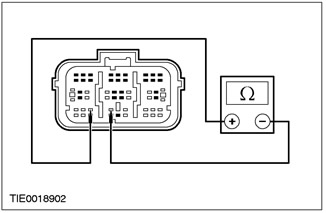
|
4 Measure the resistance between: NOTE: left hand drive variant - pin 23 C423 of the airbag control module, circuit 15S-JA15 (green-red), and pin 24, electrical circuit 91S-JA15 (black-orange), from the side of the electrical wiring. NOTE: right hand drive variant - pin 23 C423 of the airbag control module, circuit 15S-JA38 (green-orange), and pin 24, electrical circuit 91S-JA38 (black and red), from the side of the electrical wiring. |
|
• Is the resistance greater than 10,000 ohms? |
|
|
→ Yes |
|
|
REPEAT self-test, CLEAR DTCs. RE-ACTIVATE the system. |
|
|
→ No |
|
|
REPAIR circuits 15S-JA15 (green-red) and 91S-JA15 (black and orange) left-hand drive variant; 15S-JA38 (green-orange) and 91S-JA38 (black and red) right hand drive option. REPEAT self-test, CLEAR DTCs. REACTIVATE the system. |
|
PINPOINT TEST AH: DTC B2118: PASSENGER SIDE AIR BAG MODULE ELECTRICAL RESISTANCE OUT OF RANGE
|
STATES |
DETAILS/RESULTS/ACTIONS |
|
AH1: PASSENGER SIDE AIR BAG MODULE ELECTRICAL RESISTANCE CHECK |
|
|
WARNING: Wait at least one minute after disconnecting the battery ground wire before disconnecting any auxiliary restraint system connector. Failure to follow this instruction may result in injury. |
|
|
1 Deactivate the auxiliary restraint system. |
|
|
2 Drive the ON position. |
|
|
3 Perform a self-test with installed simulators. |
|
|
• Is the system functioning correctly? |
|
|
→ Yes |
|
|
INSTALL a new passenger side airbag module. For more information, refer to the Side Airbag Module available in this section. REPEAT self-test, CLEAR DTCs. RE-ACTIVATE the system. |
|
|
→ No |
|
|
CHECK the correct installation of the airbag dummy. REPEAT self-test, CLEAR DTCs. RE-ACTIVATE the system. |
|
PINPOINT TEST AI: DTC B2445: PASSENGER SIDE IMPACT SENSOR CIRCUIT SHORT TO GROUND/CIRCUIT WITH IGNITION/+ BATTERY VOLTAGE OR INTERNAL FAULT
|
STATES |
DETAILS/RESULTS/ACTIONS |
|
AI1: PASSENGER SIDE IMPACT SENSOR ELECTRICAL CIRCUIT CHECK |
|
|
WARNING: Wait at least one minute after disconnecting the battery ground wire before disconnecting any auxiliary restraint system connector. Failure to follow this instruction may result in injury. |
|
|
1 Deactivate the auxiliary restraint system. |
|
|
2 Disconnect the C427 or C428 side impact sensor. |
|
|
3 Disconnect the C423 airbag control module. |
|
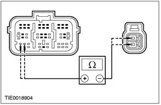
|
4 Measure the resistance between: NOTE: left hand drive variant - pin 26 C423 of the airbag control module, circuit 15S-JA40 (green-white), and pin 1 C428 side impact sensor circuit 15S-JA40 (green-white), from the wiring side; And - pin 25 C423 of the airbag control module, circuit 91-JA40 (black and white), and pin 2 C428 side impact sensor circuit 91-JA40 (black and white), from the side of the electrical wiring. NOTE: right hand drive variant - pin 26 C423 of the airbag control module, circuit 15S-JA40 (green-white), and pin 1 C427 side impact sensor circuit 15S-JA40 (green-white), from the wiring side; And - pin 25 C423 of the airbag control module, circuit 91-JA40 (black and white), and pin 2 C427 side impact sensor circuit 91-JA40 (black and white), from the side of the electrical wiring. |
|
• Is the resistance always less than 5 ohms? |
|
|
→ Yes |
|
|
Go to AI2 |
|
|
→ No |
|
|
REPAIR circuits 15S-JA40 (green and white) or 91-JA40 (black and white). REPEAT self-test, CLEAR DTCs. RE-ACTIVATE the system. |
|
|
AI2: PASSENGER SIDE SIDE IMPACT SENSOR CIRCUIT CHECK FOR SHORT CIRCUIT |
|
|
1 Disconnect the C424 airbag control module. |
|
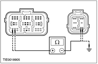
|
2 Measure the resistance between: - pin 26 C423 of the airbag control module, circuit 15S-JA40 (green-white), and pin 8 C424 of the airbag control module, circuit 15-JA10 (green-orange), from the wiring side; And - pin 26 C423 of the airbag control module, circuit 15S-JA40 (green-white), and pin 9 C424 of the airbag control module, circuit 91-JA10 (black and red), from the wiring side; And - pin 26 C423 of the airbag control module, circuit 15S-JA40 (green-white), from the wiring side, and "ground"; And - pin 25 C423 of the airbag control module, circuit 91S-JA40 (black and white), and pin 8 C424 of the airbag control module, circuit 15-JA10 (green-orange), from the wiring side; And - pin 25 C423 of the airbag control module, circuit 91S-JA40 (black and white), and pin 9 C424 of the airbag control module, circuit 91-JA10 (black and red), from the wiring side; And - pin 25 C423 of the airbag control module, circuit 91S-JA40 (black and white), from the wiring side, and "ground". |
|
• Is the resistance greater than 10,000 ohms in all cases? |
|
|
→ Yes |
|
|
INSTALL a new side impact sensor. REPEAT self-test, CLEAR DTCs. RE-ACTIVATE the system. |
|
|
→ No |
|
|
REPAIR circuits 15-JA10 (green-orange) and 15S-JA40 (green-yellow) or 91-JA40 (black and white). REPEAT self-test, CLEAR DTCs. RE-ACTIVATE the system. |
|
Visitor comments