PINPOINT TEST BS: NO COMMUNICATION WITH MODULE
|
STATES |
DETAILS/RESULTS/ACTIONS |
|
BS1: MAKE SURE THE WDS SYSTEM IS COMMUNICATING THROUGH THE DATA LINK CONNECTOR (DLC) |
|
|
WARNING: Wait at least one minute after disconnecting the battery ground cable before disconnecting any supplemental restraint system electrical connector. Failure to follow this instruction could result in personal injury. |
|
|
1Select an alternative system to test the DLC connector. |
|
|
• Can WDS communicate with the selected system? |
|
|
→ Yes |
|
|
Go to BS2 |
|
|
→ No |
|
|
CHECK the DLC connector. Refer to the Wiring Diagrams for more information. |
|
|
BS2: CHECK AIR BAG WARNING LAMP |
|
|
1Enter the ON position. |
|
|
2The airbag warning light should come on for three seconds with the ignition switch in the ON position and then go out. If a fault is present, the airbag warning light will begin to flash after five seconds. |
|
|
• Does the airbag indicator light work? |
|
|
→ Yes |
|
|
Go to BS3 |
|
|
→ No |
|
|
CHECK the instrument cluster. For more information, refer to the Wiring Diagrams. |
|
|
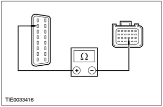
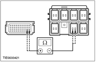
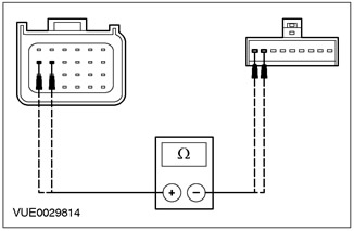
BS3: CHECK DLC CONNECTOR CIRCUIT |
|
|
1Enter the OFF position. |
|
|
2Deactivate the supplemental restraint system. For more information, refer to Supplemental Restraint System Air Bags and Seat Belt Tensioners (SRS) in this section. |
|
|
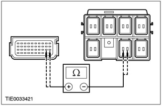
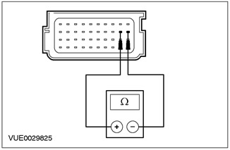
3Disconnect the Supplemental Restraint System Control Module - C424. |
|
|
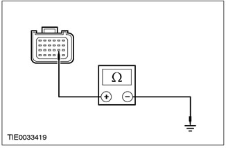
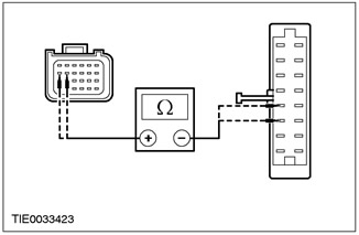
4Measure the resistance between DLC pin C200, circuit 8-EE18 (WH/BLK) and supplemental restraint system control module pin C424, circuit 8-EE7 (WH/RED), wiring harness side. |
|
• Is the resistance less than 5 ohms? |
|
|
→ Yes |
|
|
If the air bag indicator light is flashing, determine the flashing DTC and refer to the indicator light flashing DTC table in this section. INSTALL a new supplemental restraint system control module. REPEAT the self-test, CLEAR the DTCs. Reactivate the system For additional information, refer to Supplemental Restraint System Air Bags and Seat Belt Pretensioners (SRS) in this section. |
|
|
→ No |
|
|
REPAIR the 8-EE7 electrical circuit (white/red). REPEAT the self-test, CLEAR the DTC codes Reactivate the system For more information, refer to the Auxiliary Restraint System for Airbags and Seat Belt Tensioners (SRS) available in this section. |
|
PINPOINT TEST BT: DTC B1318: LOW BATTERY VOLTAGE
|
STATES |
DETAILS/RESULTS/ACTIONS |
|
BT1: CHECK BATTERY VOLTAGE |
|
|
1Enter the ON position. |
|
|
2Check the battery voltage with the ignition ON. |
|
|
• Is the battery voltage greater than 9V? |
|
|
→ Yes |
|
|
Go to BT2 |
|
|
→ No |
|
|
CHECK battery and charging system. Refer to Section 414-00 for additional information. REPEAT self-test, CLEAR DTCs. |
|
|
BT2: CHECK AIR BAG CONTROL MODULE POWER SUPPLY CIRCUIT |
|
|
WARNING: Wait at least one minute after disconnecting the battery ground cable before disconnecting any supplemental restraint system electrical connector. Failure to follow this instruction could result in personal injury. |
|
|
1Enter the OFF position. |
|
|
2Deactivate the supplemental restraint system. For more information, refer to Supplemental Restraint System Air Bags and Seat Belt Tensioners (SRS) in this section. |
|
|
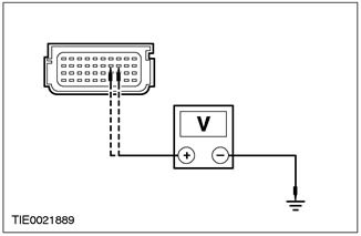
3Disconnect the Supplemental Restraint System Control Module - C424. |
|
|
4Enter the ON position. |
|
|
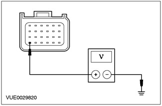
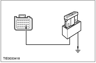
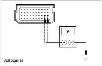
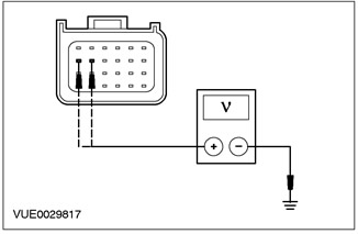
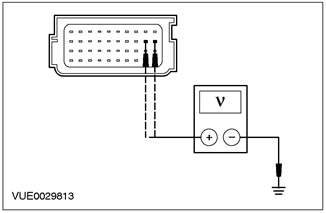
5Measure the voltage between secondary restraint system control module C424 pin 24, circuit 15-JA10 (green/orange), wiring harness side. |
|
• Is the voltage more than 10V? |
|
|
→ Yes |
|
|
Go to BT3 |
|
|
→ No |
|
|
REPAIR circuit 15-JA10 (green/orange). PERFORM the self-test. CLEAR the DTCs. REACTIVATE the system. For additional information, refer to Supplemental Restraint System Air Bags and Seat Belt Tensioners (SRS) in this section. |
|
|
BT3: CHECK AIR BAG CONTROL MODULE POWER SUPPLY CIRCUIT |
|
|
1Enter the OFF position. |
|
|
2Disconnect Fuse 60. |
|
|
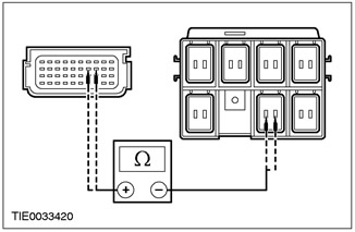
3Measure the resistance between secondary restraint system control module C424 pin 24, circuit 15-JA10 (green/orange), harness side and fuse 60, harness side. |
|
|
• Is the resistance less than 5 ohms? |
|
|
→ Yes |
|
|
REPEAT the self-test, CLEAR the DTCs, REACTIVATE the system For additional information, refer to Supplemental Restraint System (SRS) in this section. |
|
|
→ No |
|
|
REPAIR circuit 15-JA10 (green/orange). REPEAT self-test, CLEAR DTCs. REACTIVATE system For additional information, refer to Supplemental Restraint System Air Bags and Seat Belt Tensioners (SRS) in this section. |
|
PINPOINT TEST BU: DTC B1869: AIR BAG WARRANTY LAMP CIRCUIT OPEN OR SHORT TO GROUND.
|
STATES |
DETAILS/RESULTS/ACTIONS |
|
BU1: CHECK AIR BAG WARNING LAMP |
|
|
1Enter the ON position. |
|
|
2Check the airbag warning light. |
|
|
• Is the airbag indicator light on continuously? |
|
|
→ Yes |
|
|
Go to BU2 |
|
|
→ No |
|
|
Go to BU5 |
|
|
BU2: CHECK AIR BAG WARRANTY LAMP CIRCUIT |
|
|
WARNING: Wait at least one minute after disconnecting the battery ground cable before disconnecting any supplemental restraint system electrical connector. Failure to follow this instruction could result in personal injury. |
|
|
1Enter the OFF position. |
|
|
2Deactivate the supplemental restraint system. For more information, refer to Supplemental Restraint System Air Bags and Seat Belt Tensioners (SRS) in this section. |
|
|
3Disconnect the Supplemental Restraint System Control Module - C424. |
|
|
4Disconnect the Instrument Cluster - C809. |
|
|
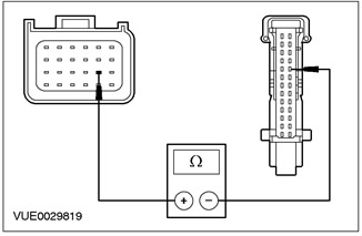
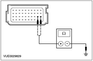
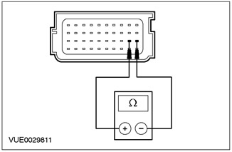
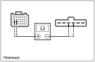
5Measure the resistance between pin 14 C424 of the secondary restraint system control module, circuit 91S-JA14 (BK/GN), wiring harness side and pin 22 C809 of the instrument cluster, circuit 91S-JA14 (BK/GN), wiring harness side. |
|
• Is the resistance less than 5 ohms? |
|
|
→ Yes |
|
|
Go to BU3 |
|
|
→ No |
|
|
REPAIR circuit 91S-JA14 (black/green). REPEAT the self-test, CLEAR the DTCs and REACTIVATE the system. For additional information, refer to Supplemental Restraint System of the Air Bags and Seat Belt Pretensioners (SRS) in this section. |
|
|
BU3: CHECK THE OPERATION OF THE AIR BAG WARNING LAMP |
|
|
1Connect the Instrument Cluster - C809. |
|
|
2Install a 7.5 A fused jumper wire between secondary restraint system control module C424 pin 14, circuit 91S-JA14 (BK/GN), harness side and ground. |
|
3Turn ON the ignition. |
|
|
• Is the airbag indicator light on? |
|
|
→ Yes |
|
|
INSTALL a new instrument cluster. REFER to section 413-01. REPEAT the self-test, CLEAR the DTCs and REACTIVATE the system. For additional information, refer to Supplemental Restraint System Air Bags and Seat Belt Pretensioners (SRS) in this section. |
|
|
→ No |
|
|
Go to BU4 |
|
|
BU4: CHECK AIR BAG WARNING LAMP OPERATION (CONTINUED) |
|
|
1Install a 7.5 A fused jumper wire between secondary restraint system control module C424 pin 14, circuit 91S-JA14 (BK/GN), harness side and ground. |
|
2Disconnect the connecting wire with the fuse from the ground. |
|
|
• Is the airbag indicator light on? |
|
|
→ Yes |
|
|
INSTALL a new supplemental restraint system control module. REPEAT the self-test, CLEAR the DTCs. REACTIVATE the system. For additional information, refer to Supplemental Restraint System Air Bags and Seat Belt Pretensioners (SRS) in this section. |
|
|
→ No |
|
|
REPEAT the self-test, CLEAR the DTCs, and REACTIVATE the system. For additional information, refer to Supplemental Restraint System (SRS) in this section. |
|
|
BU5: CHECK INSTRUMENT PANEL WARNING LAMPS |
|
|
WARNING: Wait at least one minute after disconnecting the battery ground cable before disconnecting any supplemental restraint system electrical connector. Failure to follow this instruction could result in personal injury. |
|
|
NOTE:The supplemental restraints control module will activate the audible warning only if there is a fault in the air bag indicator lamp AND another fault in the supplemental restraints system (such as an open circuit in the driver air bag module). In all cases, REPAIR the air bag indicator lamp first. |
|
|
1Enter the OFF position. |
|
|
2Deactivate the supplemental restraint system. For more information, refer to Supplemental Restraint System Air Bags and Seat Belt Tensioners (SRS) in this section. |
|
|
3Enter the ON position. |
|
|
4Check the instrument cluster indicator lights. |
|
|
• Do the indicator lights come on when the ignition is turned to the ON position? |
|
|
→ Yes |
|
|
Go to BU6 |
|
|
→ No |
|
|
CHECK the instrument cluster fuse. Refer to the Wiring Diagrams for more information. |
|
|
BU6: CHECK AIR BAG WARRANTY LAMP CIRCUIT |
|
|
1Enter the OFF position. |
|
|
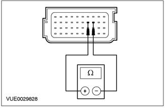
2Disconnect the Supplemental Restraint System Control Module - C424. |
|
|
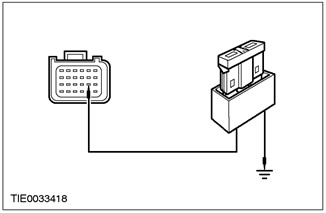
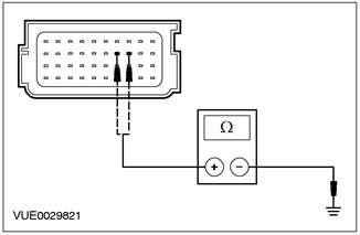
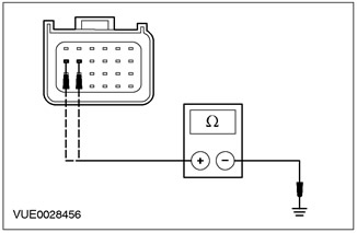
3Measure the resistance between secondary restraint system control module C424 pin 14, circuit 91S-JA14 (BK/GN), wiring harness side and ground. |
|
• Is the resistance greater than 10,000 ohms? |
|
|
→ Yes |
|
|
CHECK the air bag indicator LED/lamp. REPEAT the self-test, CLEAR the DTCs and REACTIVATE the system. For additional information, refer to Supplemental Restraint System (SRS) Air Bags and Seat Belt Pretensioners (SRS) in this section. |
|
|
→ No |
|
|
REPAIR circuit 91S-JA14 (black/green). REPEAT the self-test, CLEAR the DTCs and REACTIVATE the system. For additional information, refer to Supplemental Restraint System of the Air Bags and Seat Belt Pretensioners (SRS) in this section. |
|
PINPOINT TEST BV: DTC B1870: SHORT CIRCUIT OF THE ELECTRIC CIRCUIT OF THE AIRBAG WARNING LAMP RELATIVE TO THE BATTERY
|
STATES |
DETAILS/RESULTS/ACTIONS |
|
WARNING: Wait at least one minute after disconnecting the battery ground cable before disconnecting any supplemental restraint system electrical connector. Failure to follow this instruction could result in personal injury. |
|
|
BV1: CHECK AIR BAG WARRANTY LAMP CIRCUIT |
|
|
1Deactivate the supplemental restraint system. For more information, refer to Supplemental Restraint System Air Bags and Seat Belt Tensioners (SRS) in this section. |
|
|
2Disconnect the Supplemental Restraint System Control Module - C424. |
|
|
3Disconnect the Instrument Cluster - C809. |
|
|
4Enter the ON position. |
|
|
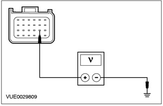
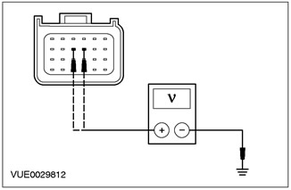
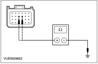
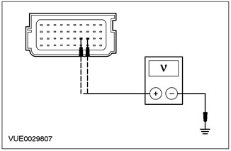
5Measure the voltage between secondary restraint system control module C424 pin 14, circuit 91S-JA14 (BK/GN), harness side and ground. |
|
• Is voltage registered? |
|
|
→ Yes |
|
|
REPAIR circuit 91S-JA14 (black/green) and 15-JA10 (green/orange) or 91S-JA14A (black/green). REPEAT self-test, CLEAR DTCs REACTIVATE system. For additional information, refer to Supplemental Restraint System Air Bags and Seat Belt Pretensioners (SRS) in this section. |
|
|
→ No |
|
|
CHECK the instrument cluster. Refer to Section 413-01 for additional information. REPEAT the self-test, CLEAR the DTCs. REACTIVATE the system. Refer to Supplemental Restraint System (SRS) in this section for additional information. |
|
PINPOINT TEST BW: DTC B1876: DRIVER SEAT BELT TENSIONER CIRCUIT CAPACITOR OUT OF RANGE
|
STATES |
DETAILS/RESULTS/ACTIONS |
|
BW1: CHECK CAPACITIVE RESISTANCE IN DRIVER SEAT BELT TENSIONER CIRCUIT |
|
|
WARNING: Wait at least one minute after disconnecting the battery ground cable before disconnecting any supplemental restraint system electrical connector. Failure to follow this instruction could result in personal injury. |
|
|
1Deactivate the supplemental restraint system. For more information, refer to Supplemental Restraint System Air Bags and Seat Belt Tensioners (SRS) in this section. |
|
|
2Enter the ON position. |
|
|
3Perform a self-test with the simulators installed. |
|
|
• Is the system functioning properly? |
|
|
→ Yes |
|
|
Go to BW2 |
|
|
→ No |
|
|
CHECK the air bag module simulator for proper installation. REPEAT the self-test, CLEAR the DTCs and REACTIVATE the system. For additional information, refer to Supplemental Restraint System (SRS) Air Bags and Seat Belt Pretensioners (SRS) in this section. |
|
|
BW2: CHECK DRIVER SEAT BELT TENSIONER CHAIN |
|
|
1Enter the OFF position. |
|
|
2Disconnect the Driver's Seat Belt Pretensioner Simulator. |
|
|
3Connect the Driver's Seat Belt Pretensioner - C30 or C31. |
|
|
4Enter the ON position. |
|
|
5Perform a self-test. |
|
|
• Is the system functioning properly? |
|
|
→ Yes |
|
|
REPEAT the self-test, CLEAR the DTCs, and REACTIVATE the system. For additional information, refer to Supplemental Restraint System (SRS) in this section. |
|
|
→ No |
|
|
INSTALL a new driver seat belt pretensioner. Refer to Section 501-20A / 501-20B for additional information. REPEAT the self-test, CLEAR the DTCs. REACTIVATE the system. Refer to Supplemental Restraint System (SRS) in this section for additional information. |
|
PINPOINT TEST BX: DTC B1877: OPEN OR HIGH RESISTANCE IN DRIVER SEAT BELT TENSIONER CIRCUIT
|
STATES |
DETAILS/RESULTS/ACTIONS |
|
BX1: CHECK DRIVER SEAT BELT TENSIONER CIRCUIT |
|
|
WARNING: Wait at least one minute after disconnecting the battery ground cable before disconnecting any supplemental restraint system electrical connector. Failure to follow this instruction could result in personal injury. |
|
|
1Deactivate the supplemental restraint system. For more information, refer to Supplemental Restraint System Air Bags and Seat Belt Tensioners (SRS) in this section. |
|
|
2Enter the ON position. |
|
|
3Perform a self-test with the simulators installed. |
|
|
• Is the system functioning properly? |
|
|
→ Yes |
|
|
Go to BX2 |
|
|
→ No |
|
|
Go to BX3 |
|
|
BX2: CHECK DRIVER SEAT BELT TENSIONER CIRCUIT |
|
|
1Enter the OFF position. |
|
|
2Disconnect the Driver's Seat Belt Pretensioner Simulator. |
|
|
3Connect the Driver's Seat Belt Pretensioner - C30 or C31. |
|
|
4Enter the ON position. |
|
|
5Perform a self-test. |
|
|
• Is the system functioning properly? |
|
|
→ Yes |
|
|
REPEAT the self-test, CLEAR the DTCs, and REACTIVATE the system. For additional information, refer to Supplemental Restraint System (SRS) in this section. |
|
|
→ No |
|
|
INSTALL a new driver seat belt pretensioner. Refer to Section 501-20A / 501-20B for additional information. REPEAT the self-test, CLEAR the DTCs. REACTIVATE the system. Refer to Supplemental Restraint System (SRS) in this section for additional information. |
|
|
BX3: CHECK DRIVER SEAT BELT TENSIONER CIRCUIT FOR OPEN OR HIGH RESISTANCE |
|
|
1Enter the OFF position. |
|
|
2Disconnect the Supplemental Restraint System Control Module - C423. |
|
|
3Disconnect the Driver's Seat Belt Pretensioner Simulator. |
|
|
4Measure the resistance between: Left-hand drive vehicles • pin 27 C423 of the secondary restraint system control module, circuit 15S-JA33 (green/blue), wiring harness side and pin 4 C30 of the underseat connector, circuit 15S-JA33 (green/blue), wiring harness side; and • pin 28 C423 of the secondary restraint system control module, circuit 91S-JA33 (black/blue), wiring harness side and pin 3 C30 of the underseat connector, circuit 91S-JA33 (black/blue), wiring harness side. |
|
Right hand drive vehicles • pin 19 C423 of the secondary restraint system control module, circuit 15S-JA34 (green/orange), wiring harness side and pin 4 C31 of the underseat connector, circuit 15S-JA34 (green/orange), wiring harness side; and • pin 20 C423 of the secondary restraint system control module, circuit 91S-JA34 (black/red), wiring harness side and pin 5 C31 of the underseat connector, circuit 91S-JA34 (black/red), wiring harness side. |
|
|
• Is the resistance less than 5 ohms in all cases? |
|
|
→ Yes |
|
|
REPEAT the self-test, CLEAR the DTCs, and REACTIVATE the system. For additional information, refer to Supplemental Restraint System (SRS) in this section. |
|
|
→ No |
|
|
REPAIR electrical circuit 15S-JA33 (Green/Blue) or 91S-JA33 (Black/Blue) (LHD); 15S-JA34 (green/orange) or 91S-JA34 (black/red) (RHD). REPEAT the self-test, CLEAR the DTCs and REACTIVATE the system. For additional information, refer to Supplemental Restraint System (SRS) in this section. |
|
PINPOINT TEST BY: DTC B1878: DRIVER SEAT BELT TENSIONER SHORT CIRCUITED TO BATTERY
|
STATES |
DETAILS/RESULTS/ACTIONS |
|
BY1: CHECK DRIVER SEAT BELT TENSIONER CHAIN |
|
|
WARNING: Wait at least one minute after disconnecting the battery ground cable before disconnecting any supplemental restraint system electrical connector. Failure to follow this instruction could result in personal injury. |
|
|
1Deactivate the supplemental restraint system. For more information, refer to Supplemental Restraint System Air Bags and Seat Belt Tensioners (SRS) in this section. |
|
|
2Enter the ON position. |
|
|
3Perform a self-test with the simulators installed. |
|
|
• Is the system functioning properly? |
|
|
→ Yes |
|
|
Go to BY2 |
|
|
→ No |
|
|
Go to BY3 |
|
|
BY2: CHECK DRIVER SEAT BELT TENSIONER CHAIN |
|
|
1Enter the OFF position. |
|
|
2Disconnect the Driver's Seat Belt Pretensioner Simulator. |
|
|
3Connect the Driver's Seat Belt Pretensioner - C30 or C31. |
|
|
4Enter the ON position. |
|
|
5Perform a self-test. |
|
|
• Is the system functioning properly? |
|
|
→ Yes |
|
|
REPEAT the self-test, CLEAR the DTCs, and REACTIVATE the system. For additional information, refer to Supplemental Restraint System (SRS) in this section. |
|
|
→ No |
|
|
INSTALL a new driver seat belt pretensioner. Refer to Section 501-20A / 501-20B for additional information. REPEAT the self-test, CLEAR the DTCs. REACTIVATE the system. Refer to Supplemental Restraint System (SRS) in this section for additional information. |
|
|
BY3: CHECK DRIVER SEAT BELT TENSIONER CIRCUIT FOR SHORT TO BATTERY |
|
|
1Enter the OFF position. |
|
|
2Disconnect the Supplemental Restraint System Control Module - C423. |
|
|
3Disconnect the Driver's Seat Belt Pretensioner Simulator. |
|
|
4Enter the ON position. |
|

|
5Measure the voltage between: Left-hand drive vehicles • pin 27 C423 auxiliary restraint system control module, circuit 15S-JA33 (green/blue), wiring harness side and ground; and • pin 28 C423 of the auxiliary restraint system control module, electrical circuit 91S-JA33 (black/blue), wiring harness side and ground. |
|
Right hand drive vehicles • pin 19 C423 auxiliary restraint system control module, circuit 15S-JA34 (green/orange), wiring harness side and ground; and • pin 20 C423 auxiliary restraint system control module, circuit 91S-JA34 (black/red), wiring harness side and ground" |
|
|
• Is voltage registered? |
|
|
→ Yes |
|
|
REPAIR electrical circuit 15S-JA33 (Green/Blue) or 91S-JA33 (Black/Blue) and 15-JA10 (Green/Orange) or 91S-JA14A (Black/Green) (LHD); 15S-JA34 (green/orange) or 91S-JA34 (black/red) and 15-JA10 (green/orange) or 91S-JA14A (black/green) (RHD). REPEAT the self-test, CLEAR the DTCs and REACTIVATE the system. For additional information, refer to Supplemental Restraint System (SRS) in this section. |
|
|
→ No |
|
|
REPEAT the self-test, CLEAR the DTCs, and REACTIVATE the system. For additional information, refer to Supplemental Restraint System (SRS) in this section. |
|
PINPOINT TEST BZ: DTC B1879: DRIVER SEAT BELT TENSIONER CIRCUIT SHORT TO GROUND"
|
STATES |
DETAILS/RESULTS/ACTIONS |
|
BZ1: CHECK DRIVER SEAT BELT TENSIONER CIRCUIT |
|
|
WARNING: Wait at least one minute after disconnecting the battery ground cable before disconnecting any supplemental restraint system electrical connector. Failure to follow this instruction could result in personal injury. |
|
|
1Deactivate the supplemental restraint system. For more information, refer to Supplemental Restraint System Air Bags and Seat Belt Tensioners (SRS) in this section. |
|
|
2Enter the ON position. |
|
|
3Perform a self-test with the simulators installed. |
|
|
• Is the system functioning properly? |
|
|
→ Yes |
|
|
Go to BZ2 |
|
|
→ No |
|
|
Go to BZ3 |
|
|
BZ2: CHECK DRIVER SEAT BELT TENSIONER CIRCUIT |
|
|
1Enter the OFF position. |
|
|
2Disconnect the Driver's Seat Belt Pretensioner Simulator. |
|
|
3Connect the Driver's Seat Belt Pretensioner - C30 or C31. |
|
|
4Enter the ON position. |
|
|
5Perform a self-test. |
|
|
• Is the system functioning properly? |
|
|
→ Yes |
|
|
REPEAT the self-test, CLEAR the DTCs, and REACTIVATE the system. For additional information, refer to Supplemental Restraint System (SRS) in this section. |
|
|
→ No |
|
|
INSTALL a new driver seat belt pretensioner. Refer to Section 501-20A / 501-20B for additional information. REPEAT the self-test, CLEAR the DTCs. REACTIVATE the system. Refer to Supplemental Restraint System (SRS) in this section for additional information. |
|
|
BZ3: CHECK DRIVER SEAT BELT TENSIONER CIRCUIT FOR SHORT TO GROUND" |
|
|
1Enter the OFF position. |
|
|
2Disconnect the Supplemental Restraint System Control Module - C423. |
|
|
3Disconnect the Driver's Seat Belt Pretensioner Simulator. |
|
|
4Measure the resistance between: Left-hand drive vehicles • pin 27 C423 auxiliary restraint system control module, circuit 15S-JA33 (green/blue), wiring harness side and ground; and • pin 28 C423 of the auxiliary restraint system control module, electrical circuit 91S-JA33 (black/blue), wiring harness side and ground. |
|
Right hand drive vehicles • pin 19 C423 auxiliary restraint system control module, circuit 15S-JA34 (green/orange), wiring harness side and ground; and • pin 20 C423 auxiliary restraint system control module, circuit 91S-JA34 (black/red), wiring harness side and ground" |
|
|
• Is the resistance greater than 10,000 ohms in all cases? |
|
|
→ Yes |
|
|
REPEAT the self-test, CLEAR the DTCs, and REACTIVATE the system. For additional information, refer to Supplemental Restraint System (SRS) in this section. |
|
|
→ No |
|
|
REPAIR electrical circuit 15S-JA33 (Green/Blue) or 91S-JA33 (Black/Blue) and 91-JA10 (Black/Red) (LHD); 15S-JA34 (green/orange), or 91S-JA34 (black/red) and 91-JA10 (black/red) (RHD). REPEAT the self-test, CLEAR the DTCs and REACTIVATE the system. For additional information, refer to Supplemental Restraint System Air Bags and Seat Belt Pretensioners (SRS) in this section. |
|
PINPOINT TEST CA: DTC B1880: PASSENGER SEAT BELT TENSIONER CIRCUIT CAPACITANCE OUT OF PERMISSIBLE RANGE
|
STATES |
DETAILS/RESULTS/ACTIONS |
|
CA1: CHECK DRIVER SEAT BELT TENSIONER CIRCUIT CAPACITIVE RESISTANCE |
|
|
WARNING: Wait at least one minute after disconnecting the battery ground cable before disconnecting any supplemental restraint system electrical connector. Failure to follow this instruction could result in personal injury. |
|
|
1Deactivate the supplemental restraint system. For more information, refer to Supplemental Restraint System Air Bags and Seat Belt Tensioners (SRS) in this section. |
|
|
2Enter the ON position. |
|
|
3Perform a self-test with the simulators installed. |
|
|
• Is the system functioning properly? |
|
|
→ Yes |
|
|
Go to CA2 |
|
|
→ No |
|
|
CHECK the airbag simulator for proper installation. REPEAT the self-test, CLEAR the DTCs and REACTIVATE the system. For additional information, refer to Supplemental Restraint System (SRS) Airbags and Seat Belt Pretensioners (SRS) in this section. |
|
|
CA2: CHECK DRIVER SEAT BELT TENSIONER CIRCUIT |
|
|
1Enter the OFF position. |
|
|
2Disconnect the Passenger Seat Belt Pretensioner Simulator. |
|
|
3Connect the Passenger Seat Belt Pretensioner - C30 or C31. |
|
|
4Enter the ON position. |
|
|
5Perform a self-test. |
|
|
• Is the system functioning properly? |
|
|
→ Yes |
|
|
REPEAT the self-test, CLEAR the DTCs, and REACTIVATE the system. For additional information, refer to Supplemental Restraint System (SRS) in this section. |
|
|
→ No |
|
|
INSTALL a new passenger seat belt. Refer to Section 501-20A / 501-20B for additional information. REPEAT the self-test, CLEAR the DTCs, and REACTIVATE the system. Refer to Supplemental Restraint System (SRS) in this section for additional information. |
|
PINPOINT TEST CB: DTC 1881: PASSENGER SEAT BELT TENSIONER CIRCUIT OPEN OR HIGH RESISTANCE
|
STATES |
DETAILS/RESULTS/ACTIONS |
|
CB1: CHECK PASSENGER SEAT BELT TENSIONER CIRCUIT |
|
|
WARNING: Wait at least one minute after disconnecting the battery ground cable before disconnecting any supplemental restraint system electrical connector. Failure to follow this instruction could result in personal injury. |
|
|
1Deactivate the supplemental restraint system. For more information, refer to Supplemental Restraint System Air Bags and Seat Belt Tensioners (SRS) in this section. |
|
|
2Enter the ON position. |
|
|
3Perform a self-test with the simulators installed. |
|
|
• Is the system functioning properly? |
|
|
→ Yes |
|
|
Go to CB2 |
|
|
→ No |
|
|
Go to CB3 |
|
|
CB2: CHECK PASSENGER SEAT BELT TENSIONER CIRCUIT |
|
|
1Enter the OFF position. |
|
|
2Disconnect the Passenger Seat Belt Pretensioner Simulator. |
|
|
3Connect the Passenger Seat Belt Pretensioner - C30 or C31. |
|
|
4Enter the ON position. |
|
|
5Perform a self-test. |
|
|
• Is the system functioning properly? |
|
|
→ Yes |
|
|
REPEAT the self-test, CLEAR the DTCs, and REACTIVATE the system. For additional information, refer to Supplemental Restraint System (SRS) in this section. |
|
|
→ No |
|
|
INSTALL a new passenger seat belt pretensioner. Refer to Section 501-20A / 501-20B for additional information. REPEAT the self-test, CLEAR the DTCs. REACTIVATE the system. Refer to Supplemental Restraint System (SRS) in this section for additional information. |
|
|
CB3: CHECK PASSENGER SEAT BELT TENSIONER CIRCUIT FOR OPEN OR HIGH RESISTANCE |
|
|
1Enter the OFF position. |
|
|
2Disconnect the Supplemental Restraint System Control Module - C423. |
|
|
3Disconnect the Passenger Seat Belt Pretensioner Simulator. |
|

|
4Measure the resistance between: Left-hand drive vehicles • pin 19 C423 of the secondary restraint system control module, circuit 15S-JA34 (green/orange), wiring harness side and pin 4 C31 of the underseat connector, circuit 15S-JA34 (green/orange), wiring harness side; and • pin 20 C423 of the supplemental restraint system control module, circuit 91S-JA34 (black/red), wiring harness side, and pin 5 C31 of the underseat connector, circuit 91S-JA34 (black/red), wiring harness side. |
|
Right hand drive vehicles • pin 27 C423 of the secondary restraint system control module, circuit 15S-JA33 (green/blue), wiring harness side, and pin 4 C30 of the underseat connector, circuit 15S-JA33 (green/blue), wiring harness side; and • pin 28 C423 of the secondary restraint system control module, circuit 91S-JA33 (black/blue), wiring harness side, and pin 3 C30 of the underseat connector, circuit 91S-JA33 (black/blue), wiring harness side. |
|
|
• Is the resistance less than 5 ohms in all cases? |
|
|
→ Yes |
|
|
REPEAT the self-test, CLEAR the DTCs, and REACTIVATE the system. For additional information, refer to Supplemental Restraint System (SRS) in this section. |
|
|
→ No |
|
|
REPAIR electrical circuits 15S-JA34 (Green/Orange) or 91S-JA34 (Black/Red) (LHD); 15S-JA33 (green/blue) or 91S-JA33 (black/blue) (RHD). REPEAT the self-test, CLEAR the DTCs and REACTIVATE the system. For additional information, refer to Supplemental Restraint System Air Bags and Seat Belt Tensioners (SRS) in this section. |
|
PINPOINT TEST CC: DTC B1882: PASSENGER SEAT BELT TENSIONER SHORT TO BATTERY
|
STATES |
DETAILS/RESULTS/ACTIONS |
|
CC1: CHECK PASSENGER SEAT BELT TENSIONER CIRCUIT |
|
|
WARNING: Wait at least one minute after disconnecting the battery ground cable before disconnecting any supplemental restraint system electrical connector. Failure to follow this instruction could result in personal injury. |
|
|
1Deactivate the supplemental restraint system. For more information, refer to Supplemental Restraint System Air Bags and Seat Belt Tensioners (SRS) in this section. |
|
|
2Enter the ON position. |
|
|
3Perform a self-test with the simulators installed. |
|
|
• Is the system functioning properly? |
|
|
→ Yes |
|
|
Go to CC2 |
|
|
→ No |
|
|
Go to CC3 |
|
|
CC2: CHECK PASSENGER SEAT BELT TENSIONER CIRCUIT |
|
|
1Enter the OFF position. |
|
|
2Disconnect the Passenger Seat Belt Pretensioner Simulator. |
|
|
3Connect the Passenger Seat Belt Pretensioner - C30 or C31. |
|
|
4Enter the ON position. |
|
|
5Perform a self-test. |
|
|
• Is the system functioning properly? |
|
|
→ Yes |
|
|
REPEAT the self-test, CLEAR the DTCs, and REACTIVATE the system. For additional information, refer to Supplemental Restraint System (SRS) in this section. |
|
|
→ No |
|
|
INSTALL a new passenger seat belt pretensioner. Refer to Section 501-20A / 501-20B for additional information. REPEAT the self-test, CLEAR the DTCs. REACTIVATE the system. Refer to Supplemental Restraint System (SRS) in this section for additional information. |
|
|
CC3: CHECK PASSENGER SEAT BELT TENSIONER CIRCUIT FOR SHORT TO BATTERY |
|
|
1Enter the OFF position. |
|
|
2Disconnect the Supplemental Restraint System Control Module - C423. |
|
|
3Disconnect the Passenger Seat Belt Pretensioner Simulator. |
|
|
4Enter the ON position. |
|

|
5Measure the voltage between: Left-hand drive vehicles • pin 19 C423 auxiliary restraint system control module, circuit 15S-JA34 (green/orange), wiring harness side and ground; and • pin 20 C423 auxiliary restraint system control module, circuit 91S-JA34 (black/red), wiring harness side and ground" |
|
Right hand drive vehicles • pin 27 C423 auxiliary restraint system control module, circuit 15S-JA33 (green/blue), wiring harness side and ground; and • pin 28 C423 of the auxiliary restraint system control module, electrical circuit 91S-JA33 (black/blue), wiring harness side and ground. |
|
|
• Is voltage registered? |
|
|
→ Yes |
|
|
REPAIR electrical circuits 15-JA10 (green/orange) and 15S-JA34 (green/orange) or 91S-JA34 (black/red) (LHD); 15-JA10 (green/orange) and 15S-JA33 (green/blue) or 91S-JA33 (black/blue) (RHD). REPEAT the self-test, CLEAR the DTCs and REACTIVATE the system. For additional information, refer to Supplemental Restraint System Air Bags and Seat Belt Pretensioners (SRS) in this section. |
|
|
→ No |
|
|
Repeat the self-test. CLEAR the DTCs. REACTIVATE the system. For additional information, refer to Supplemental Restraint System (SRS) in this section. |
|
PINPOINT TEST CD: DTC B1883: PASSENGER SEAT BELT TENSIONER SHORT TO GROUND"
|
STATES |
DETAILS/RESULTS/ACTIONS |
|
CD1: CHECK PASSENGER SEAT BELT TENSIONER CHAIN |
|
|
WARNING: Wait at least one minute after disconnecting the battery ground cable before disconnecting any supplemental restraint system electrical connector. Failure to follow this instruction could result in personal injury. |
|
|
1Deactivate the supplemental restraint system. For more information, refer to Supplemental Restraint System Air Bags and Seat Belt Tensioners (SRS) in this section. |
|
|
2Enter the ON position. |
|
|
3Perform a self-test with the simulators installed. |
|
|
• Is the system functioning properly? |
|
|
→ Yes |
|
|
Go to CD2 |
|
|
→ No |
|
|
Go to CD3 |
|
|
CD2: CHECK PASSENGER SEAT BELT TENSIONER CHAIN |
|
|
1Enter the OFF position. |
|
|
2Disconnect the Passenger Seat Belt Pretensioner Simulator. |
|
|
3Connect the Passenger Seat Belt Pretensioner - C30 or C31. |
|
|
4Enter the ON position. |
|
|
5Perform a self-test. |
|
|
• Is the system functioning properly? |
|
|
→ Yes |
|
|
REPEAT the self-test, CLEAR the DTCs, and REACTIVATE the system. For additional information, refer to Supplemental Restraint System (SRS) in this section. |
|
|
→ No |
|
|
INSTALL a new passenger seat belt pretensioner. Refer to Section 501-20A / 501-20B for additional information. REPEAT the self-test, CLEAR the DTCs. REACTIVATE the system. Refer to Supplemental Restraint System (SRS) in this section for additional information. |
|
|
CD3: CHECK PASSENGER SEAT BELT TENSIONER CIRCUIT FOR SHORT TO GROUND" |
|
|
1Enter the OFF position. |
|
|
2Disconnect the Supplemental Restraint System Control Module - C423. |
|
|
3Disconnect the Passenger Seat Belt Pretensioner Simulator. |
|


|
4Measure the resistance between: Left-hand drive vehicles • pin 19 C423 auxiliary restraint system control module, circuit 15S-JA34 (green/orange), wiring harness side and ground; and • pin 20 C423 auxiliary restraint system control module, circuit 91S-JA34 (black/red), wiring harness side and ground" |
|
Right hand drive vehicles • pin 27 C423 auxiliary restraint system control module, circuit 15S-JA33 (green/blue), wiring harness side and ground; and • pin 28 C423 of the auxiliary restraint system control module, electrical circuit 91S-JA33 (black/blue), wiring harness side and ground. |
|
|
• Is the resistance greater than 10,000 ohms in all cases? |
|
|
→ Yes |
|
|
REPEAT the self-test, CLEAR the DTCs, and REACTIVATE the system. For additional information, refer to Supplemental Restraint System (SRS) in this section. |
|
|
→ No |
|
|
REPAIR electrical circuits 15S-JA34 (green/orange) or 91S-JA34 (black/red) and 91-JA10 (black/red) (LHD);15S-JA33 (green/blue) or 91S-JA33 (black/blue) and 91-JA10 (black/red) (RHD). REPEAT the self-test, CLEAR the DTCs and REACTIVATE the system. For additional information, refer to Supplemental Restraint System Air Bags and Seat Belt Pretensioners (SRS) in this section. |
|
PINPOINT TEST CE: DTC B1885: DRIVER SEAT BELT CIRCUIT LOW RESISTANCE
|
STATES |
DETAILS/RESULTS/ACTIONS |
|
CE1: CHECK DRIVER SEAT BELT TENSIONER CIRCUIT |
|
|
WARNING: Wait at least one minute after disconnecting the battery ground cable before disconnecting any supplemental restraint system electrical connector. Failure to follow this instruction could result in personal injury. |
|
|
1Deactivate the supplemental restraint system. For more information, refer to Supplemental Restraint System Air Bags and Seat Belt Tensioners (SRS) in this section. |
|
|
2Enter the ON position. |
|
|
3Perform a self-test with the simulators installed. |
|
|
• Is the system functioning properly? |
|
|
→ Yes |
|
|
Go to CE2 |
|
|
→ No |
|
|
Go to CE3 |
|
|
CE2: CHECK DRIVER SEAT BELT TENSIONER CIRCUIT |
|
|
1Enter the OFF position. |
|
|
2Disconnect the Driver's Seat Belt Pretensioner Simulator. |
|
|
3Connect the Driver's Seat Belt Pretensioner - C30 or C31. |
|
|
4Enter the ON position. |
|
|
5Perform a self-test. |
|
|
• Is the system functioning properly? |
|
|
→ Yes |
|
|
REPEAT the self-test, CLEAR the DTCs, and REACTIVATE the system. For additional information, refer to Supplemental Restraint System (SRS) in this section. |
|
|
→ No |
|
|
INSTALL a new driver seat belt pretensioner. Refer to Section 501-20A / 501-20B for additional information. REPEAT the self-test, CLEAR the DTCs. REACTIVATE the system. Refer to Supplemental Restraint System (SRS) in this section for additional information. |
|
|
CE3: CHECK DRIVER SEAT BELT TENSIONER CIRCUIT FOR LOW RESISTANCE |
|
|
1Enter the OFF position. |
|
|
2Disconnect the Supplemental Restraint System Control Module - C423. |
|
|
3Disconnect the Driver's Seat Belt Pretensioner Simulator. |
|

|
4Measure the resistance between: Left-hand drive vehicles • pin 27 C423 of the auxiliary restraint system control module, circuit 15S-JA33 (green/blue), and pin 28, circuit 91S-JA33 (black/blue), on the wiring harness side. |
|
Right hand drive vehicles • pin 19 C423 of the auxiliary restraint system control module, circuit 15S-JA34 (green/orange), and pin 20, circuit 91S-JA34 (black/red), on the wiring harness side. |
|
|
• Is the resistance greater than 10,000 ohms? |
|
|
→ Yes |
|
|
REPEAT the self-test, CLEAR the DTCs, and REACTIVATE the system. For additional information, refer to Supplemental Restraint System (SRS) in this section. |
|
|
→ No |
|
|
REPAIR electrical circuits 15S-JA33 (green/blue) and 91S-JA33 (black/blue) (LHD); or 15S-JA34 (green/orange) and 91S-JA34 (black/red) (RHD). REPEAT the self-test, CLEAR the DTCs and REACTIVATE the system. For additional information, refer to Supplemental Restraint System (SRS) Air Bags and Seat Belt Tensioners (SRS) in this section. |
|
PINPOINT TEST CF: DTC B1886: PASSENGER SEAT BELT TENSIONER CIRCUIT LOW RESISTANCE
|
STATES |
DETAILS/RESULTS/ACTIONS |
|
CF1: CHECK PASSENGER SEAT BELT TENSIONER CIRCUIT |
|
|
WARNING: Wait at least one minute after disconnecting the battery ground cable before disconnecting any supplemental restraint system electrical connector. Failure to follow this instruction could result in personal injury. |
|
|
1Deactivate the supplemental restraint system. For more information, refer to Supplemental Restraint System Air Bags and Seat Belt Tensioners (SRS) in this section. |
|
|
2Enter the ON position. |
|
|
3Perform a self-test with the simulators installed. |
|
|
• Is the system functioning properly? |
|
|
→ Yes |
|
|
Go to CF2 |
|
|
→ No |
|
|
Go to CF3 |
|
|
CF2: CHECK DRIVER SEAT BELT TENSIONER CIRCUIT |
|
|
1Enter the OFF position. |
|
|
2Disconnect the Passenger Seat Belt Pretensioner Simulator. |
|
|
3Connect the Passenger Seat Belt Pretensioner - C30 or C31. |
|
|
4Enter the ON position. |
|
|
5Perform a self-test. |
|
|
• Is the system functioning properly? |
|
|
→ Yes |
|
|
REPEAT the self-test, CLEAR the DTCs, and REACTIVATE the system. For additional information, refer to Supplemental Restraint System (SRS) in this section. |
|
|
→ No |
|
|
INSTALL a new passenger seat belt pretensioner. Refer to Section 501-20A / 501-20B for additional information. REPEAT the self-test, CLEAR the DTCs. REACTIVATE the system. Refer to Supplemental Restraint System (SRS) in this section for additional information. |
|
|
CF3: CHECK PASSENGER SEAT BELT TENSIONER CIRCUIT FOR LOW RESISTANCE |
|
|
1Enter the OFF position. |
|
|
2Disconnect the Supplemental Restraint System Control Module - C423. |
|
|
3Disconnect the Passenger Seat Belt Pretensioner Simulator. |
|

|
4Measure the resistance between: Left-hand drive vehicles • pin 27 C423 of the auxiliary restraint system control module, circuit 15S-JA33 (green/blue), and pin 28, circuit 91S-JA33 (black/blue), on the wiring harness side. |
|
Right hand drive vehicles • pin 19 C423 of the auxiliary restraint system control module, circuit 15S-JA34 (green/orange), and pin 20, circuit 91S-JA34 (black/red), on the wiring harness side. |
|
|
• Does the resistance exceed 10,000 ohms? |
|
|
→ Yes |
|
|
REPEAT the self-test, CLEAR the DTCs, and REACTIVATE the system. For additional information, refer to Supplemental Restraint System (SRS) in this section. |
|
|
→ No |
|
|
REPAIR electrical circuits 15S-JA33 (green/blue) and 91S-JA33 (black/blue) (LHD); or 15S-JA34 (green/orange) and 91S-JA34 (black/red) (RHD). REPEAT the self-test, CLEAR the DTCs and REACTIVATE the system. For additional information, refer to Supplemental Restraint System (SRS) Air Bags and Seat Belt Tensioners (SRS) in this section. |
|
PINPOINT TEST CG: DTC B1916: DRIVER AIR BAG STAGE 1 CIRCUIT SHORT TO BATTERY
|
STATES |
DETAILS/RESULTS/ACTIONS |
|
CG1: CHECK THE ADDITIONAL AIRBAG WIRING HARNESS FOR A SHORT CIRCUIT RELATIVE TO THE BATTERY |
|
|
WARNING: Wait at least one minute after disconnecting the battery ground cable before disconnecting any supplemental restraint system electrical connector. Failure to follow this instruction could result in personal injury. |
|
|
1Deactivate the supplemental restraint system. For more information, refer to Supplemental Restraint System Air Bags and Seat Belt Tensioners (SRS) in this section. |
|
|
2Disconnect the Driver's First Stage Airbag Simulator. |
|
|
3Disconnect the Supplemental Restraint System Control Module - C424. |
|
|
4Enter the ON position. |
|

|
5Measure the voltage between: • pin 12 C424 auxiliary restraint system control module, circuit 15S-JA8 (green/red), wiring harness side and ground; • pin 11 C424 of the auxiliary restraint system control module, circuit 91S-JA8 (black/orange), wiring harness side and ground. |
|
• Is voltage registered? |
|
|
→ Yes |
|
|
Go to CG2 |
|
|
→ No |
|
|
CONNECT the driver air bag module simulator and the supplemental restraints control module. REPEAT the self-test, CLEAR the DTCs, and REACTIVATE the system. For additional information, refer to Supplemental Restraint System (SRS) in this section. |
|
|
CG2: CHECK CLOCK SPRING CIRCUIT FOR SHORT TO BATTERY |
|
|
1Enter the OFF position. |
|
|
2Disconnect Driver Airbag Wiring Harness - C921. |
|
|
3Enter the ON position. |
|
|
4Measure the voltage between: • pin 12 C424 auxiliary restraint system control module, circuit 15S-JA8 (green/red) wiring harness side and ground; and • pin 11 C424 of the auxiliary restraint system control module, electrical circuit 91S-JA8 (black/orange) on the wiring harness side and ground. |
|
5Turn the steering wheel between extreme positions and record the resistance values. |
|
|
• Is voltage registered? |
|
|
→ Yes |
|
|
Go to CG3 |
|
|
→ No |
|
|
INSTALL a new air bag wiring harness. REPEAT the self-test, CLEAR the DTCs and REACTIVATE the system. For additional information, refer to Supplemental Restraint System (SRS) Air Bags and Seat Belt Pretensioners (SRS) in this section. |
|
|
CG3: CHECK THE AIRBAG WIRING HARNESS FOR A SHORT CIRCUIT RELATIVE TO THE BATTERY |
|
|
1Enter the OFF position. |
|
|
2Disconnect Clock Spring - C896 or C898. |
|
|
3Enter the ON position. |
|

|
4Measure the voltage between: • pin 12 C424 auxiliary restraint system control module, circuit 15S-JA8 (green/red) wiring harness side and ground; and • pin 11 C424 of the auxiliary restraint system control module, electrical circuit 91S-JA8 (black/orange) on the wiring harness side and ground. |
|
• Is voltage registered? |
|
|
→ Yes |
|
|
REPAIR circuit 15S-JA8 (green/red) or 91S-JA8 (black/orange) and 15-JA10 (green/orange) or 91S-JA14A (black/green). REPEAT self-test, CLEAR DTCs REACTIVATE the system. For additional information, refer to Supplemental Restraint System (SRS) in this section. |
|
|
→ No |
|
|
INSTALL a new clock spring. For additional information, refer to Clock Spring in this section. REPEAT the self-test, CLEAR the DTCs. REACTIVATE the system. For additional information, refer to Supplemental Restraint System of the Air Bags and Seat Belt Pretensioners (SRS) in this section. |
|
PINPOINT TEST CH: DTC B1925: PASSENGER AIR BAG STAGE 1 CIRCUIT SHORT TO BATTERY
|
STATES |
DETAILS/RESULTS/ACTIONS |
|
CH1: CHECK THE PASSENGER AIRBAG CIRCUIT FOR A SHORT CIRCUIT RELATIVE TO THE BATTERY |
|
|
WARNING: Wait at least one minute after disconnecting the battery ground cable before disconnecting any supplemental restraint system electrical connector. Failure to follow this instruction could result in personal injury. |
|
|
1Deactivate the supplemental restraint system. For more information, refer to Supplemental Restraint System Air Bags and Seat Belt Tensioners (SRS) in this section. |
|
|
2Disconnect the Passenger Air Bag Module Stage 1 Simulator. |
|
|
3Disconnect the Supplemental Restraint System Control Module - C424. |
|
|
4Enter the ON position. |
|
|
5Measure the voltage between: • pin 9 C424 auxiliary restraint system control module, circuit 15S-JA31 (green/white) wiring harness side and ground; and • pin 10 C424 of the auxiliary restraint system control module, electrical circuit 91S-JA31 (black/white) on the wiring harness side and ground. |
|
• Is voltage registered? |
|
|
→ Yes |
|
|
REPAIR circuits 15S-JA31 (green/white) and 91S-JA31 (black/white). REPEAT the self-test, CLEAR the DTCs and REACTIVATE the system. For additional information, refer to Supplemental Restraint System of the Air Bags and Seat Belt Pretensioners (SRS) in this section. |
|
|
→ No |
|
|
CONNECT the passenger air bag module simulator and the supplemental restraints control module. REPEAT the self-test, CLEAR the DTCs, and REACTIVATE the system. For additional information, refer to Supplemental Restraint System (SRS) in this section. |
|
PINPOINT TEST CI: DTC B1932: OPEN OR HIGH RESISTANCE IN DRIVER STAGE 1 AIR BAG CIRCUIT
|
STATES |
DETAILS/RESULTS/ACTIONS |
|
CI1: CHECK RESISTANCE OF DRIVER AIR BAG STAGE 1 CIRCUIT |
|
|
WARNING: Wait at least one minute after disconnecting the battery ground cable before disconnecting any supplemental restraint system electrical connector. Failure to follow this instruction could result in personal injury. |
|
|
1Deactivate the supplemental restraint system. For more information, refer to Supplemental Restraint System Air Bags and Seat Belt Tensioners (SRS) in this section. |
|
|
2Enter the ON position. |
|
|
3Perform a self-test with the simulators installed. |
|
|
• Is the system functioning properly? |
|
|
→ Yes |
|
|
Go to CI2 |
|
|
→ No |
|
|
Go to CI3 |
|
|
CI2: CHECK DRIVER AIR BAG MODULE IGNITION RESISTANCE |
|
|
WARNING: Do not continue this test without WDS. Failure to follow this instruction may result in injury. |
|
|
1Connect the test and deployment wire to the driver airbag module - stage one. |
|
|
2Select the DMM option in WDS. |
|
|
3Connect the test and deployment wire to the WDS. |
|
|
4Measure the resistance of the air bag module igniter circuit. |
|
|
5Connect the test and deployment wire to the driver airbag module - stage two. |
|

|
6Measure the resistance of the air bag module igniter circuit. |
|
• Is the resistance between 2 and 3 ohms? |
|
|
→ Yes |
|
|
REPEAT the self-test, CLEAR the DTCs, and REACTIVATE the system. For additional information, refer to Supplemental Restraint System (SRS) in this section. |
|
|
→ No |
|
|
INSTALL a new driver air bag module. For additional information, refer to Driver Air Bag Module in this section. REPEAT the self-test, CLEAR the DTCs. REACTIVATE the system. For additional information, refer to Supplemental Restraint System (SRS) in this section. |
|
|
CI3: CHECK AIR BAG WIRING HARNESS FOR OPEN OR HIGH RESISTANCE |
|
|
1Enter the OFF position. |
|
|
2Disconnect the Air Bag Module Wiring Harness - C921. |
|
|
3Measure the resistance between: • pin 12 C424 of the auxiliary restraint system control module, circuit 15S-JA8 (green/red), wiring harness side and pin 3 C921 of the clock spring wiring harness, circuit 15S-JA8 (green/red), component side; and • pin 11 C424 of the auxiliary restraint system control module, circuit 91S-JA8 (black/orange), wiring harness side and pin 4 C921 of the clock spring wiring harness, circuit 91S-JA8 (black/orange), component side. |
|
4Turn the steering wheel between extreme positions and record the resistance values. |
|
|
• Is the resistance less than 5 ohms in all cases? |
|
|
→ Yes |
|
|
INSTALL a new air bag wiring harness. REPEAT the self-test, CLEAR the DTCs and REACTIVATE the system. For additional information, refer to Supplemental Restraint System (SRS) Air Bags and Seat Belt Pretensioners (SRS) in this section. |
|
|
→ No |
|
|
Go to CI4 |
|
|
CI4: CHECK CLOCK SPRING CIRCUIT FOR OPEN OR HIGH RESISTANCE |
|
|
1Disconnect Clock Spring - C896 or C898. |
|
|
2Measure the resistance between: Vehicles with stability control • pin 12 C424 auxiliary restraint system control module, circuit 15S-JA8 (green/red), wiring harness side and pin 9 C896 clock spring, circuit 15S-JA8 (green/red), wiring harness side; and • pin 11 C424 of the auxiliary restraint system control module, circuit 91S-JA8 (black/orange), wiring harness side and pin 8 C896 of the clock spring, circuit 91S-JA8 (black/orange), wiring harness side. |
|
Vehicles without stability control. • pin 12 C424 auxiliary restraint system control module, circuit 15S-JA8 (green/red), wiring harness side and pin 4 C898 clock spring, circuit 15S-JA8 (green/red), wiring harness side; and • pin 11 C424 of the auxiliary restraint system control module, circuit 91S-JA8 (black/orange), wiring harness side and pin 3 C898 of the clock spring, circuit 91S-JA8 (black/orange), wiring harness side. |
|
|
• Is the resistance less than 5 ohms in all cases? |
|
|
→ Yes |
|
|
Install a new clock spring. For additional information, refer to Clock Spring in this section. REPEAT the self-test, CLEAR the DTCs. REACTIVATE the system. For additional information, refer to Supplemental Restraint System of the Air Bags and Seat Belt Pretensioners (SRS) in this section. |
|
|
→ No |
|
|
REPAIR circuit 15S-JA8 (Green/Red) or 91S-JA8 (Black/Orange). REPEAT the self-test, CLEAR the DTCs and REACTIVATE the system. For additional information, refer to Supplemental Restraint System (SRS) in this section. |
|
PINPOINT TEST CJ: DTC B1933: OPEN OR HIGH RESISTANCE IN PASSENGER AIR BAG STAGE 1 CIRCUIT
|
STATES |
DETAILS/RESULTS/ACTIONS |
|
CJ1: CHECK RESISTANCE OF PASSENGER AIR BAG STAGE 1 CIRCUIT |
|
|
WARNING: Wait at least one minute after disconnecting the battery ground cable before disconnecting any supplemental restraint system electrical connector. Failure to follow this instruction could result in personal injury. |
|
|
1Deactivate the supplemental restraint system. For more information, refer to Supplemental Restraint System Air Bags and Seat Belt Tensioners (SRS) in this section. |
|
|
2Enter the ON position. |
|
|
3Perform a self-test with the simulators installed. |
|
|
• Is the system functioning properly? |
|
|
→ Yes |
|
|
Go to CJ2 |
|
|
→ No |
|
|
REPAIR circuit 15S-JA31 (Green/White) or 91S-JA31 (Black/White). REPEAT self-test, CLEAR DTCs REACTIVATE system. For additional information, refer to Supplemental Restraint System (SRS) in this section. |
|
|
CJ2: CHECK RESISTANCE OF PASSENGER AIR BAG MODULE IGNITOR |
|
|
WARNING: Do not continue this test without the WDS. Failure to follow this instruction may result in injury. |
|
|
1Connect the test and deployment wire to the passenger air bag module - stage one. |
|
|
2Select the DMM option in WDS. |
|
|
3Connect the test and deployment wire to the WDS. |
|
|
4Measure the resistance of the air bag module igniter circuit. |
|
|
5Connect the test and deployment wire to the passenger air bag module - stage two. |
|
|
6Measure the resistance of the air bag module igniter circuit. |
|
• Are the resistance values between 2 and 3 ohms? |
|
|
→ Yes |
|
|
REPEAT the self-test, CLEAR the DTCs, and REACTIVATE the system. For additional information, refer to Supplemental Restraint System (SRS) in this section. |
|
|
→ No |
|
|
INSTALL a new passenger air bag module. REPEAT the self-test, CLEAR the DTCs. REACTIVATE the system. For additional information, refer to Supplemental Restraint System (SRS) Air Bags and Seat Belt Tensioners (SRS) in this section. |
|
PINPOINT TEST CK: DTC B1934: LOW RESISTANCE IN DRIVER STAGE 1 AIR BAG CIRCUIT
|
STATES |
DETAILS/RESULTS/ACTIONS |
|
CK1: CHECK RESISTANCE IN DRIVER AIR BAG STAGE 1 CIRCUIT |
|
|
WARNING: Wait at least one minute after disconnecting the battery ground cable before disconnecting any supplemental restraint system electrical connector. Failure to follow this instruction could result in personal injury. |
|
|
1Deactivate the supplemental restraint system. For more information, refer to Supplemental Restraint System Air Bags and Seat Belt Tensioners (SRS) in this section. |
|
|
2Enter the ON position. |
|
|
3Perform a self-test with the simulators installed. |
|
|
• Is the system functioning properly? |
|
|
→ Yes |
|
|
Go to CK2 |
|
|
→ No |
|
|
Go to CK3 |
|
|
CK2: CHECK AIR BAG MODULE IGNITOR RESISTANCE |
|
|
WARNING: Do not continue this test without the WDS. Failure to follow this instruction may result in injury. |
|
|
1Connect the test and deployment wire to the driver airbag module - stage one. |
|
|
2Select the DMM option in WDS. |
|
|
3Connect the test and deployment wire to the WDS. |
|
|
4Measure the resistance of the air bag module igniter circuit. |
|
|
5Connect the test and deployment wire to the driver airbag module - stage two. |
|

|
6Measure the resistance of the air bag module igniter circuit. |
|
• Are the resistance values between 2 and 3 ohms? |
|
|
→ Yes |
|
|
REPEAT the self-test, CLEAR the DTCs, and REACTIVATE the system. For additional information, refer to Supplemental Restraint System (SRS) in this section. |
|
|
→ No |
|
|
INSTALL a new driver air bag module. For additional information, refer to Driver Air Bag Module in this section. REPEAT the self-test, CLEAR the DTCs. REACTIVATE the system. For additional information, refer to Supplemental Restraint System (SRS) in this section. |
|
|
CK3: CHECK AIR BAG WIRING HARNESS FOR LOW RESISTANCE |
|
|
1Enter the OFF position. |
|
|
2Disconnect the Air Bag Module Wiring Harness - C921. |
|
|
3Measure the resistance between the supplemental restraint system control module C424 pin 12, circuit 15S-JA8 (GN/RD) and pin 11, circuit 91S-JA8 (BK/OG), wiring harness side. |
|
4Turn the steering wheel between extreme positions and record the resistance values. |
|
|
• Is the resistance greater than 10,000 ohms? |
|
|
→ Yes |
|
|
INSTALL a new air bag wiring harness. REPEAT the self-test, CLEAR the DTCs. REACTIVATE the system. For additional information, refer to Supplemental Restraint System (SRS) Air Bags and Seat Belt Pretensioners (SRS) in this section. |
|
|
→ No |
|
|
Go to CK4 |
|
|
CK4: CHECK CLOCK SPRING CIRCUIT FOR LOW RESISTANCE |
|
|
1Disconnect Clock Spring - C896 or C898. |
|
|
2Measure the resistance between the supplemental restraint system control module C424 pin 12, circuit 15S-JA8 (GN/RD) and pin 11, circuit 91S-JA8 (BK/OG), wiring harness side. |
|
• Is the resistance greater than 10,000 ohms? |
|
|
→ Yes |
|
|
INSTALL a new clock spring. For additional information, refer to Clock Spring in this section. REPEAT the self-test, CLEAR the DTCs. REACTIVATE the system. For additional information, refer to Supplemental Restraint System of the Air Bags and Seat Belt Pretensioners (SRS) in this section. |
|
|
→ No |
|
|
REPAIR circuit 15S-JA8 (green/red) and 91S-JA8 (black/orange). REPEAT self-test, CLEAR DTCs REACTIVATE system. For additional information, refer to Supplemental Restraint System Air Bags and Seat Belt Pretensioners (SRS) in this section. |
|
PINPOINT TEST CL: DTC B1935: PASSENGER AIR BAG STAGE 1 CIRCUIT LOW RESISTANCE
|
STATES |
DETAILS/RESULTS/ACTIONS |
|
CL1: CHECK RESISTANCE IN PASSENGER AIR BAG STAGE 1 CIRCUIT |
|
|
WARNING: Wait at least one minute after disconnecting the battery ground cable before disconnecting any supplemental restraint system electrical connector. Failure to follow this instruction could result in personal injury. |
|
|
1Deactivate the supplemental restraint system. For more information, refer to Supplemental Restraint System Air Bags and Seat Belt Tensioners (SRS) in this section. |
|
|
2Enter the ON position. |
|
|
3Perform a self-test with the simulators installed. |
|
|
• Is the system functioning properly? |
|
|
→ Yes |
|
|
Go to CL2 |
|
|
→ No |
|
|
Go to CL3 |
|
|
CL2: CHECK RESISTANCE OF PASSENGER AIR BAG MODULE IGNITOR |
|
|
WARNING: Do not continue this test without the WDS. Failure to follow this instruction may result in injury. |
|
|
1Connect the test and deployment wire to the passenger air bag module - stage one. |
|
|
2Select the DMM option in WDS. |
|
|
3Connect the test and deployment wire to the WDS. |
|
|
4Measure the resistance of the air bag module igniter circuit. |
|
|
5Connect the test and deployment wire to the passenger air bag module - stage two. |
|

|
6Measure the resistance of the air bag module igniter circuit. |
|
• Are the resistance values between 2 and 3 ohms? |
|
|
→ Yes |
|
|
REPEAT the self-test, CLEAR the DTCs, and REACTIVATE the system. For additional information, refer to Supplemental Restraint System (SRS) in this section. |
|
|
→ No |
|
|
INSTALL a new passenger air bag module. REPEAT the self-test, CLEAR the DTCs. REACTIVATE the system. For additional information, refer to Supplemental Restraint System (SRS) Air Bags and Seat Belt Tensioners (SRS) in this section. |
|
|
CL3: CHECK PASSENGER AIR BAG CIRCUIT FOR LOW RESISTANCE |
|
|
1Enter the OFF position. |
|
|
2Disconnect the Passenger First Stage Airbag Simulator. |
|
|
3Disconnect the Supplemental Restraint System Control Module - C424. |
|
|
4Measure the resistance between the supplemental restraint system control module C424 pin 9, circuit 15S-JA31 (GN/WH) and pin 10, circuit 91S-JA31 (BK/WH), wiring harness side. |
|
• Is the resistance greater than 10,000 ohms? |
|
|
→ Yes |
|
|
REPEAT the self-test, CLEAR the DTCs, and REACTIVATE the system. For additional information, refer to Supplemental Restraint System (SRS) in this section. |
|
|
→ No |
|
|
REPAIR circuits 15S-JA31 (green/white) and 91S-JA31 (black/white). REPEAT the self-test, CLEAR the DTCs and REACTIVATE the system. For additional information, refer to Supplemental Restraint System of the Air Bags and Seat Belt Pretensioners (SRS) in this section. |
|
PINPOINT TEST CM: DTC B1936: SHORT TO GROUND IN DRIVER STAGE 1 AIR BAG CIRCUIT
|
STATES |
DETAILS/RESULTS/ACTIONS |
|
CM1: CHECK DRIVER AIR BAG STAGE 1 CIRCUIT |
|
|
WARNING: Wait at least one minute after disconnecting the battery ground cable before disconnecting any supplemental restraint system electrical connector. Failure to follow this instruction could result in personal injury. |
|
|
1Deactivate the supplemental restraint system. For more information, refer to Supplemental Restraint System Air Bags and Seat Belt Tensioners (SRS) in this section. |
|
|
2Enter the ON position. |
|
|
3Perform a self-test with the simulators installed. |
|
|
• Is the system functioning properly? |
|
|
→ Yes |
|
|
Go to CM2 |
|
|
→ No |
|
|
Go to CM3 |
|
|
CM2: CHECK DRIVER AIR BAG MODULE |
|
|
WARNING: Do not continue this test without the WDS. Failure to follow this instruction may result in injury. |
|
|
1Connect the test and deployment wire to the driver airbag module - stage one. |
|
|
2Select the DMM option in WDS. |
|
|
3Connect the test and deployment wire to the WDS. |
|
|
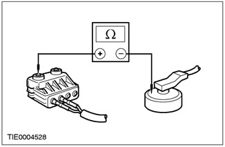
4Measure the resistance between each terminal and the airbag module housing. |
|
|
5Connect the test and deployment wire to the driver airbag module - stage two. |
|

|
6Measure the resistance between each terminal and the airbag module housing. |
|
• Is the resistance in all cases greater than 10,000 ohms? |
|
|
→ Yes |
|
|
REPEAT the self-test, CLEAR the DTCs, and REACTIVATE the system. For additional information, refer to Supplemental Restraint System (SRS) in this section. |
|
|
→ No |
|
|
INSTALL a new driver air bag module. For additional information, refer to Driver Air Bag Module in this section. REPEAT the self-test, CLEAR the DTCs. REACTIVATE the system. For additional information, refer to Supplemental Restraint System (SRS) in this section. |
|
|
CM3: CHECK DRIVER AIR BAG STAGE 1 WIRING HARNESS FOR SHORT TO GROUND" |
|
|
1Enter the OFF position. |
|
|
2Disconnect the Supplemental Restraint System Control Module - C424. |
|
|
3Disconnect the Driver Air Bag Module Stage 1 Simulator. |
|
|
4Measure the resistance between: • pin 12 C424 auxiliary restraint system control module, circuit 15S-JA8 (green/red), wiring harness side and ground; and • pin 11 C424 auxiliary restraint system control module, circuit 91S- JA8 (black/orange), wiring harness side and ground. |
|
5Turn the steering wheel between extreme positions and record the voltage values. |
|
|
• Is the resistance in all cases greater than 10,000 ohms? |
|
|
→ Yes |
|
|
REPEAT the self-test, CLEAR the DTCs, and REACTIVATE the system. For additional information, refer to Supplemental Restraint System (SRS) in this section. |
|
|
→ No |
|
|
Go to CM4 |
|
|
CM4: CHECK CLOCK SPRING CIRCUIT FOR SHORT TO GROUND" |
|
|
1Disconnect Clock Spring - C896 or C898. |
|

|
2Measure the resistance between: • pin 12 C424 auxiliary restraint system control module, circuit 15S-JA8 (green/red), wiring harness side and ground; and • pin 11 C424 auxiliary restraint system control module, circuit 91S- JA8 (black/orange), wiring harness side and ground. |
|
• Is the resistance in all cases greater than 10,000 ohms? |
|
|
→ Yes |
|
|
INSTALL a new clock spring. For additional information, refer to Clock Spring in this section. REPEAT the self-test, CLEAR the DTCs. REACTIVATE the system. For additional information, refer to Supplemental Restraint System of the Air Bags and Seat Belt Pretensioners (SRS) in this section. |
|
|
→ No |
|
|
REPAIR circuits 15S-JA8 (green/red) and 91S-JA8 (black/orange). REPEAT the self-test, CLEAR the DTCs and REACTIVATE the system. For additional information, refer to Supplemental Restraint System of the Air Bags and Seat Belt Pretensioners (SRS) in this section. |
|
PINPOINT TEST CN: DTC B1938: PASSENGER AIR BAG MODULE SHORT TO GROUND"
|
STATES |
DETAILS/RESULTS/ACTIONS |
|
CN1: CHECK RESISTANCE IN PASSENGER AIR BAG STAGE 1 CIRCUIT |
|
|
WARNING: Wait at least one minute after disconnecting the battery ground cable before disconnecting any supplemental restraint system electrical connector. Failure to follow this instruction could result in personal injury. |
|
|
1Deactivate the supplemental restraint system. For more information, refer to Supplemental Restraint System Air Bags and Seat Belt Tensioners (SRS) in this section. |
|
|
2Enter the ON position. |
|
|
3Perform a self-test with the simulators installed. |
|
|
• Is the system functioning properly? |
|
|
→ Yes |
|
|
Go to CN₂ |
|
|
→ No |
|
|
Go to CN3 |
|
|
CN₂: CHECK PASSENGER AIR BAG MODULE |
|
|
WARNING: Do not continue this test without the WDS. Failure to follow this instruction may result in injury. |
|
|
1Connect the test and deployment wire to the passenger air bag module - stage one. |
|
|
2Select the DMM option in WDS. |
|
|
3Connect the test and deployment wire to the WDS. |
|
|
4Measure the resistance between each terminal and the airbag module housing. |
|
|
5Connect the test and deployment wire to the passenger air bag module - stage two. |
|
|
6Measure the resistance between each terminal and the airbag module housing. |
|
• Is the resistance in all cases greater than 10,000 ohms? |
|
|
→ Yes |
|
|
REPEAT the self-test, CLEAR the DTCs, and REACTIVATE the system. For additional information, refer to Supplemental Restraint System (SRS) in this section. |
|
|
→ No |
|
|
INSTALL a new passenger air bag module. REPEAT the self-test, CLEAR the DTCs. REACTIVATE the system. For additional information, refer to Supplemental Restraint System (SRS) Air Bags and Seat Belt Tensioners (SRS) in this section. |
|
|
CN3: CHECK PASSENGER AIR BAG STAGE 1 WIRING HARNESS FOR SHORT TO GROUND" |
|
|
1Enter the OFF position. |
|
|
2Disconnect the Supplemental Restraint System Control Module - C424. |
|
|
3Disconnect the Passenger Air Bag Module Stage 1 Simulator. |
|
|
4Measure the resistance between: • pin 9 C424 auxiliary restraint system control module, circuit 15S-JA31 (green/white), wiring harness side and ground; and • pin 10 C424 of the auxiliary restraint system control module, electrical circuit 91S- JA31 (black/white), wiring harness side and ground. |
|
• Is the resistance in all cases greater than 10,000 ohms? |
|
|
→ Yes |
|
|
REPEAT the self-test, CLEAR the DTCs, and REACTIVATE the system. For additional information, refer to Supplemental Restraint System (SRS) in this section. |
|
|
→ No |
|
|
REPAIR circuits 15S-JA31 (green/white) and 91S-JA31 (black/white). REPEAT the self-test CLEAR the DTCs. REACTIVATE the system. For additional information, refer to Supplemental Restraint System of the Air Bags and Seat Belt Pretensioners (SRS) in this section. |
|
PINPOINT TEST CO: DTC B1992: DRIVER SIDE AIR BAG CIRCUIT SHORT TO BATTERY
|
STATES |
DETAILS/RESULTS/ACTIONS |
|
CO1: CHECK DRIVER AIR BAG CIRCUIT |
|
|
WARNING: Wait at least one minute after disconnecting the battery ground cable before disconnecting any supplemental restraint system electrical connector. Failure to follow this instruction could result in personal injury. |
|
|
1Deactivate the supplemental restraint system. For more information, refer to Supplemental Restraint System Air Bags and Seat Belt Tensioners (SRS) in this section. |
|
|
2Enter the ON position. |
|
|
3Perform a self-test with the simulators installed. |
|
|
• Is the system functioning properly? |
|
|
→ Yes |
|
|
INSTALL a new driver side airbag module. For additional information, refer to Side Airbag Module in this section. REPEAT the self-test, CLEAR the DTCs. REACTIVATE the system. For additional information, refer to Supplemental Restraint System (SRS) in this section. |
|
|
→ No |
|
|
Go to CO₂ |
|
|
CO₂: CHECK DRIVER SIDE AIR BAG MODULE CIRCUIT FOR SHORT TO BATTERY |
|
|
1Enter the OFF position. |
|
|
2Disconnect the Supplemental Restraint System Control Module - C423. |
|
|
3Disconnect the Driver Side Air Bag Module Simulator. |
|
|
4Enter the ON position. |
|
|
5Measure the voltage between: Left-hand drive vehicles • pin 30 C423 auxiliary restraint system control module, circuit 15S-JA37 (green/black), wiring harness side and ground; and • pin 29 C423 of the auxiliary restraint system control module, circuit 91S-JA37 (black/green), wiring harness side and ground. |
|
Right hand drive vehicles • pin 17 C423 auxiliary restraint system control module, circuit 15S-JA38 (green/orange), wiring harness side and ground; and • pin 18 C423 of the auxiliary restraint system control module, electrical circuit 91S-JA38 (black/red), wiring harness side and ground. |
|
|
• Is voltage registered? |
|
|
→ Yes |
|
|
REPAIR electrical circuit 15S-JA37 (Green/Black) or 91S-JA37 (Black/Green) (LHD) and 15-JA10 (Green/Orange) or 91S-JA14A (Black/Green); 15S-JA38 (green/orange) or 91S-JA38 (black/red) (RHD) and 15-JA10 (green/orange) or 91S-JA14A (black/green). REPEAT the self-test, CLEAR the DTCs and REACTIVATE the system. For additional information, refer to Supplemental Restraint System (SRS) in this section. |
|
|
→ No |
|
|
PERFORM the self-test. CLEAR the DTCs. REACTIVATE the system. For additional information, refer to Supplemental Restraint System (SRS) Air Bags and Seat Belt Tensioners (SRS) in this section. |
|
PINPOINT TEST CP: DTC B1993: DRIVER SIDE AIR BAG CIRCUIT SHORT TO GROUND.
|
STATES |
DETAILS/RESULTS/ACTIONS |
|
CP1: CHECK DRIVER SIDE AIR BAG CIRCUIT |
|
|
WARNING: Wait at least one minute after disconnecting the battery ground cable before disconnecting any supplemental restraint system electrical connector. Failure to follow this instruction could result in personal injury. |
|
|
1Deactivate the supplemental restraint system. For more information, refer to Supplemental Restraint System Air Bags and Seat Belt Tensioners (SRS) in this section. |
|
|
2Enter the ON position. |
|
|
3Perform a self-test with the simulators installed. |
|
|
• Is the system functioning properly? |
|
|
→ Yes |
|
|
INSTALL a new driver side airbag module. For additional information, refer to Side Airbag Module in this section. REPEAT the self-test, CLEAR the DTCs. REACTIVATE the system. For additional information, refer to Supplemental Restraint System (SRS) in this section. |
|
|
→ No |
|
|
Go to CP2 |
|
|
CP2: CHECK DRIVER SIDE AIR BAG CIRCUIT FOR SHORT TO GROUND. |
|
|
1Enter the OFF position. |
|
|
2Disconnect the Supplemental Restraint System Control Module - C423. |
|
|
3Disconnect the Driver Side Air Bag Module Simulator. |
|
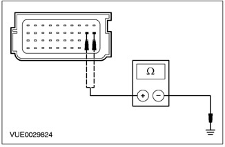

|
4Measure the resistance between: Left-hand drive vehicles • pin 30 C423 auxiliary restraint system control module, circuit 15S-JA37 (green/black), wiring harness side and ground; and • pin 29 C423 of the auxiliary restraint system control module, circuit 91S-JA37 (black/green), wiring harness side and ground. |
|
Right hand drive vehicles • pin 17 C423 auxiliary restraint system control module, circuit 15S-JA38 (green/orange), wiring harness side and ground; and • pin 18 C423 of the auxiliary restraint system control module, electrical circuit 91S-JA38 (black/red), wiring harness side and ground. |
|
|
• Is the resistance in all cases greater than 10,000 ohms? |
|
|
→ Yes |
|
|
PERFORM the self-test. CLEAR the DTCs. REACTIVATE the system. For additional information, refer to Supplemental Restraint System (SRS) Air Bags and Seat Belt Tensioners (SRS) in this section. |
|
|
→ No |
|
|
REPAIR electrical circuit 15S-JA37 (Green/Black) or 91S-JA37 (Black/Green) (LHD) and 91-JA10 (Black/Red); 15S-JA38 (green/orange) or 91S-JA38 (black/red) (RHD) and 91-JA10 (black/red). REPEAT the self-test, CLEAR the DTCs and REACTIVATE the system. For additional information, refer to Supplemental Restraint System Air Bags and Seat Belt Pretensioners (SRS) in this section. |
|
PINPOINT TEST CQ: DTC B1994: DRIVER SIDE AIR BAG CIRCUIT OPEN OR HIGH RESISTANCE
|
STATES |
DETAILS/RESULTS/ACTIONS |
|
CQ1: CHECK DRIVER SIDE AIR BAG CIRCUIT |
|
|
WARNING: Wait at least one minute after disconnecting the battery ground cable before disconnecting any supplemental restraint system electrical connector. Failure to follow this instruction could result in personal injury. |
|
|
1Deactivate the supplemental restraint system. For more information, refer to Supplemental Restraint System Air Bags and Seat Belt Tensioners (SRS) in this section. |
|
|
2Enter the ON position. |
|
|
3Perform a self-test with the simulators installed. |
|
|
• Is the system functioning properly? |
|
|
→ Yes |
|
|
Before installing a new driver side air bag module, MAKE SURE that the electrical connector located under the seat is properly seated in the connector block located under the driver seat. PERFORM the self-test. INSTALL a new driver side air bag module. For additional information, refer to Side Air Bag Module in this section. REPEAT the self-test, CLEAR the DTCs. REACTIVATE the system. For additional information, refer to Supplemental Restraint System (SRS) and Seat Belt Pretensioners (SRS) in this section. |
|
|
→ No |
|
|
Go to CQ2 |
|
|
CQ2: CHECK DRIVER SIDE AIR BAG CIRCUIT FOR OPEN OR HIGH RESISTANCE |
|
|
1Disconnect the Supplemental Restraint System Control Module - C423. |
|
|
2Disconnect the Driver Side Air Bag Module Simulator. |
|
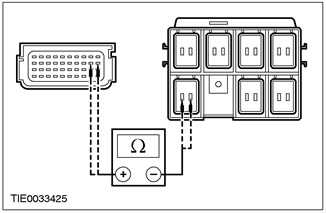
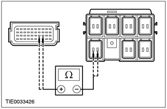
|
3Measure the resistance between: Left-hand drive vehicles • pin 30 C423 of the secondary restraint system control module, circuit 15S-JA37 (green/black), wiring harness side and pin 1 C30 of the underseat connector, circuit 15S-JA37 (green/black), wiring harness side; and • pin 29 C423 of the secondary restraint system control module, circuit 91S-JA37 (black/green), wiring harness side and pin 2 C30 of the underseat connector, circuit 91S-JA37 (black/green), wiring harness side. |
|
Right hand drive vehicles • pin 17 C423 of the secondary restraint system control module, circuit 15S-JA38 (green/orange), wiring harness side and pin 1 C31 of the underseat connector, circuit 15S-JA38 (green/orange), wiring harness side; and • pin 18 C423 of the secondary restraint system control module, circuit 91S-JA38 (black/red), wiring harness side and pin 2 C31 of the underseat connector, circuit 91S-JA38 (black/red), wiring harness side. |
|
|
• Is the resistance less than 5 ohms in all cases? |
|
|
→ Yes |
|
|
REPEAT the self-test, CLEAR the DTCs, and REACTIVATE the system. For additional information, refer to Supplemental Restraint System (SRS) in this section. |
|
|
→ No |
|
|
REPAIR electrical circuit 15S-JA37 (Green/Black) or 91S-JA37 (Black/Green) (LHD); 15S-JA38 (green/orange) or 91S-JA38 (black/red) (RHD). REPEAT the self-test, CLEAR the DTCs and REACTIVATE the system. For additional information, refer to Supplemental Restraint System Air Bags and Seat Belt Tensioners (SRS) in this section. |
|
PINPOINT TEST CR: DTC B1995: DRIVER SIDE AIR BAG CIRCUIT LOW RESISTANCE
|
STATES |
DETAILS/RESULTS/ACTIONS |
|
CR1: CHECK DRIVER SIDE AIR BAG CIRCUIT |
|
|
WARNING: Wait at least one minute after disconnecting the battery ground cable before disconnecting any supplemental restraint system electrical connector. Failure to follow this instruction could result in personal injury. |
|
|
1Deactivate the supplemental restraint system. For more information, refer to Supplemental Restraint System Air Bags and Seat Belt Tensioners (SRS) in this section. |
|
|
2Enter the ON position. |
|
|
3Perform a self-test with the simulators installed. |
|
|
• Is the system functioning properly? |
|
|
→ Yes |
|
|
INSTALL a new driver side airbag module. For additional information, refer to Side Airbag Module in this section. REPEAT the self-test, CLEAR the DTCs. REACTIVATE the system. For additional information, refer to Supplemental Restraint System (SRS) in this section. |
|
|
→ No |
|
|
Go to CR2 |
|
|
CR2: CHECK DRIVER SIDE AIR BAG CIRCUIT FOR LOW RESISTANCE |
|
|
1Enter the OFF position. |
|
|
2Disconnect the Supplemental Restraint System Control Module - C423. |
|
|
3Disconnect the Driver Side Air Bag Module Simulator. |
|


|
4Measure the resistance between: Left-hand drive vehicles • pin 30 C423 of the auxiliary restraint system control module, circuit 15S-JA37 (green/black) and pin 29, circuit 91S-JA37 (black/green), wiring harness side. |
|
Right hand drive vehicles • pin 17 C423 of the auxiliary restraint system control module, circuit 15S-JA38 (green/orange) and pin 18, circuit 91S-JA38 (black/red) on the wiring harness side. |
|
|
• Is the resistance greater than 10,000 ohms? |
|
|
→ Yes |
|
|
REPEAT the self-test, CLEAR the DTCs, and REACTIVATE the system. For additional information, refer to Supplemental Restraint System (SRS) in this section. |
|
|
→ No |
|
|
REPAIR electrical circuits 15S-JA37 (Green/Black) and 91S-JA37 (Black/Green) (LHD); 15S-JA38 (green/orange) and 91S-JA38 (black/red) (RHD). REPEAT the self-test, CLEAR the DTCs and REACTIVATE the system. For additional information, refer to Supplemental Restraint System Air Bags and Seat Belt Pretensioners (SRS) in this section. |
|
PINPOINT TEST CS: DTC 1996: PASSENGER SIDE AIR BAG CIRCUIT SHORT TO BATTERY.
|
STATES |
DETAILS/RESULTS/ACTIONS |
|
CS1: CHECK PASSENGER AIR BAG CIRCUIT |
|
|
WARNING: Wait at least one minute after disconnecting the battery ground cable before disconnecting any supplemental restraint system electrical connector. Failure to follow this instruction could result in personal injury. |
|
|
1Deactivate the supplemental restraint system. For more information, refer to Supplemental Restraint System Air Bags and Seat Belt Tensioners (SRS) in this section. |
|
|
2Enter the ON position. |
|
|
3Perform a self-test with the simulators installed. |
|
|
• Is the system functioning properly? |
|
|
→ Yes |
|
|
INSTALL a new passenger side air bag module. PERFORM the self-test. CLEAR the DTCs. For additional information, refer to Side Air Bag Module in this section. REACTIVATE the system. For additional information, refer to Supplemental Restraint System (SRS) and Seat Belt Pretensioners (SRS) in this section. |
|
|
→ No |
|
|
Go to CS2 |
|
|
CS2: CHECK THE PASSENGER SIDE AIRBAG CIRCUIT FOR A SHORT CIRCUIT RELATIVE TO THE BATTERY |
|
|
1Enter the OFF position. |
|
|
2Disconnect the Supplemental Restraint System Control Module - C423. |
|
|
3Disconnect the Passenger Side Air Bag Module Simulator. |
|
|
4Enter the ON position. |
|


|
5Measure the voltage between: Left-hand drive vehicles • pin 17 C423 auxiliary restraint system control module, circuit 15S-JA38 (green/orange), wiring harness side and ground; and • pin 18 C423 of the auxiliary restraint system control module, electrical circuit 91S-JA38 (black/red), wiring harness side and ground. |
|
Right hand drive vehicles • pin 30 C423 auxiliary restraint system control module, circuit 15S-JA37 (green/black), wiring harness side and ground; and • pin 29 C423 of the auxiliary restraint system control module, circuit 91S-JA37 (black/green), wiring harness side and ground. |
|
|
• Is voltage registered? |
|
|
→ Yes |
|
|
REPAIR electrical circuits 15S-JA38 (green/orange), or 91S-JA38 (black/red) (LHD) and 15-JA10 (green/orange); 15S-JA37 (green/black) or 91S-JA37 (black/green) (RHD) and 15-JA10 (green/orange).. REPEAT the self-test, CLEAR the DTCs REACTIVATE the system. For additional information, refer to Supplemental Restraint System Air Bags and Seat Belt Pretensioners (SRS) in this section. |
|
|
→ No |
|
|
REPEAT the self-test, CLEAR the DTCs, and REACTIVATE the system. For additional information, refer to Supplemental Restraint System (SRS) in this section. |
|
PINPOINT TEST CT: DTC B1997: PASSENGER SIDE AIR BAG CIRCUIT SHORT TO GROUND"
|
STATES |
DETAILS/RESULTS/ACTIONS |
|
CT1: CHECK PASSENGER SIDE AIR BAG CIRCUIT |
|
|
WARNING: Wait at least one minute after disconnecting the battery ground cable before disconnecting any supplemental restraint system electrical connector. Failure to follow this instruction could result in personal injury. |
|
|
1Deactivate the supplemental restraint system. For more information, refer to Supplemental Restraint System Air Bags and Seat Belt Tensioners (SRS) in this section. |
|
|
2Enter the ON position. |
|
|
3Perform a self-test with the simulators installed. |
|
|
• Is the system functioning properly? |
|
|
→ Yes |
|
|
INSTALL a new passenger side air bag module. For additional information, refer to Side Air Bag Module in this section. REPEAT the self-test, CLEAR the DTCs. REACTIVATE the system. For additional information, refer to Supplemental Restraint System (SRS) in this section. |
|
|
→ No |
|
|
Go to CT2 |
|
|
CT2: CHECK PASSENGER SIDE AIR BAG CIRCUIT FOR SHORT TO GROUND" |
|
|
1Enter the OFF position. |
|
|
2Disconnect the Supplemental Restraint System Control Module - C423. |
|
|
3Disconnect the Passenger Side Air Bag Module Simulator. |
|
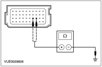
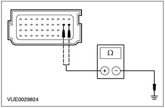
|
4Measure the resistance between: Left-hand drive vehicles • pin 17 C423 auxiliary restraint system control module, circuit 15S-JA38 (green/orange), wiring harness side and ground; and • pin 18 C423 of the auxiliary restraint system control module, electrical circuit 91S-JA38 (black/red), wiring harness side and ground. |
|
Right hand drive vehicles • pin 30 C423 auxiliary restraint system control module, circuit 15S-JA37 (green/black), wiring harness side and ground; and • pin 29 C423 of the auxiliary restraint system control module, circuit 91S-JA37 (black/green), wiring harness side and ground. |
|
|
• Is the resistance in all cases greater than 10,000 ohms? |
|
|
→ Yes |
|
|
PERFORM the self-test. CLEAR the DTCs. REACTIVATE the system. For additional information, refer to Supplemental Restraint System (SRS) Air Bags and Seat Belt Tensioners (SRS) in this section. |
|
|
→ No |
|
|
REPAIR electrical circuits 15S-JA38 (green/orange), or 91S-JA38 (black/red) (LHD) and 91-JA10 (black/red); 15S-JA37 (green/black) or 91S-JA37 (RHD) and 91-JA10 (black/red). REPEAT the self-test, CLEAR the DTCs and REACTIVATE the system. For additional information, refer to Supplemental Restraint System Air Bags and Seat Belt Pretensioners (SRS) in this section. |
|
PINPOINT TEST CU: DTC B1998: PASSENGER SIDE AIR BAG CIRCUIT OPEN OR HIGH RESISTANCE
|
STATES |
DETAILS/RESULTS/ACTIONS |
|
CU1: CHECK PASSENGER SIDE AIR BAG CIRCUIT |
|
|
WARNING: Wait at least one minute after disconnecting the battery ground cable before disconnecting any supplemental restraint system electrical connector. Failure to follow this instruction could result in personal injury. |
|
|
1Deactivate the supplemental restraint system. For more information, refer to Supplemental Restraint System Air Bags and Seat Belt Tensioners (SRS) in this section. |
|
|
2Enter the ON position. |
|
|
3Perform a self-test with the simulators installed. |
|
|
• Is the system functioning properly? |
|
|
→ Yes |
|
|
Before installing a new passenger side air bag module, MAKE SURE that the electrical connector located under the seat is properly seated in the connector block located under the passenger seat. REPEAT the self-test. INSTALL a new passenger side air bag module. For additional information, refer to Side Air Bag Module in this section. REPEAT the self-test, CLEAR the DTCs. REACTIVATE the system. For additional information, refer to Supplemental Restraint System (SRS) and Seat Belt Pretensioners (SRS) in this section. |
|
|
→ No |
|
|
Go to CU2 |
|
|
CU2: CHECK PASSENGER SIDE AIR BAG CIRCUIT FOR OPEN OR HIGH RESISTANCE |
|
|
1Disconnect the Supplemental Restraint System Control Module - C423. |
|
|
2Disconnect the Passenger Side Air Bag Module Simulator. |
|


|
3Measure the resistance between: Left-hand drive vehicles • pin 17 C423 of the secondary restraint system control module, circuit 15S-JA38 (green/orange), wiring harness side and pin 1 C31 of the underseat connector, circuit 15S-JA38 (green/orange), wiring harness side; and • pin 18 C423 of the secondary restraint system control module, circuit 91S-JA38 (black/red), wiring harness side and pin 2 C31 of the underseat connector, circuit 91S-JA38 (black/red), wiring harness side. |
|
Right hand drive vehicles • pin 30 C423 of the secondary restraint system control module, circuit 15S-JA37 (green/black), wiring harness side and pin 1 C30 of the underseat connector, circuit 15S-JA37 (green/black), wiring harness side; and • pin 29 C423 of the secondary restraint system control module, circuit 91S-JA37 (black/green), wiring harness side and pin 2 C30 of the underseat connector, circuit 91S-JA33 (black/green), wiring harness side. |
|
|
• Is the resistance less than 5 ohms in all cases? |
|
|
→ Yes |
|
|
REPEAT the self-test, CLEAR the DTCs, and REACTIVATE the system. For additional information, refer to Supplemental Restraint System (SRS) in this section. |
|
|
→ No |
|
|
REPAIR electrical circuit 15S-JA38 (green/orange), or 91S-JA38 (black/red) (LHD); 15S-JA37 (Green/Black) or 91S-JA37 (Black/Green) (RHD). REPEAT the self-test, CLEAR the DTCs and REACTIVATE the system. For additional information, refer to Supplemental Restraint System Air Bags and Seat Belt Tensioners (SRS) in this section. |
|
PINPOINT TEST CV: DTC B1999: PASSENGER SIDE AIR BAG CIRCUIT LOW RESISTANCE
|
STATES |
DETAILS/RESULTS/ACTIONS |
|
CV1: CHECK PASSENGER SIDE AIR BAG CIRCUIT |
|
|
WARNING: Wait at least one minute after disconnecting the battery ground cable before disconnecting any supplemental restraint system electrical connector. Failure to follow this instruction could result in personal injury. |
|
|
1Deactivate the supplemental restraint system. For more information, refer to Supplemental Restraint System Air Bags and Seat Belt Tensioners (SRS) in this section. |
|
|
2Enter the ON position. |
|
|
3Perform a self-test with the simulators installed. |
|
|
• Is the system functioning properly? |
|
|
→ Yes |
|
|
INSTALL a new passenger side air bag module. For additional information, refer to Side Air Bag Module in this section. REPEAT the self-test, CLEAR the DTCs. REACTIVATE the system. For additional information, refer to Supplemental Restraint System (SRS) in this section. |
|
|
→ No |
|
|
Go to CV2 |
|
|
CV2: CHECK PASSENGER SIDE AIR BAG CIRCUIT FOR LOW RESISTANCE |
|
|
1Enter the OFF position. |
|
|
2Disconnect the Supplemental Restraint System Control Module - C423. |
|
|
3Disconnect the Passenger Side Air Bag Module Simulator. |
|
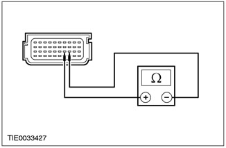

|
4Measure the resistance between: Left-hand drive vehicles • pin 17 C423 of the auxiliary restraint system control module, circuit 15S-JA38 (green/orange) and pin 18, circuit 91S-JA38 (black/red) on the wiring harness side. |
|
Right hand drive vehicles • pin 30 C423 of the auxiliary restraint system control module, circuit 15S-JA37 (green/black) and pin 29, circuit 91S-JA37 (black/green), wiring harness side. |
|
|
• Is the resistance greater than 10,000 ohms? |
|
|
→ Yes |
|
|
REPEAT the self-test, CLEAR the DTCs, and REACTIVATE the system. For additional information, refer to Supplemental Restraint System (SRS) in this section. |
|
|
→ No |
|
|
REPAIR electrical circuits 15S-JA38 (green/orange) and 91S-JA38 (black/red) (LHD); or 15S-JA37 (green/black) and 91S-JA37 (black/green) (RHD). REPEAT the self-test, CLEAR the DTCs and REACTIVATE the system. For additional information, refer to Supplemental Restraint System (SRS) in this section. |
|
PINPOINT TEST CW: DTC B2117: DRIVER SIDE AIR BAG MODULE CAPACITOR OUT OF RANGE
|
STATES |
DETAILS/RESULTS/ACTIONS |
|
CW1: CHECK DRIVER SIDE AIR BAG MODULE CAPACITIVE RESISTOR |
|
|
WARNING: Wait at least one minute after disconnecting the battery ground cable before disconnecting any supplemental restraint system electrical connector. Failure to follow this instruction could result in personal injury. |
|
|
1Deactivate the supplemental restraint system. For more information, refer to Supplemental Restraint System Air Bags and Seat Belt Tensioners (SRS) in this section. |
|
|
2Enter the ON position. |
|
|
3Perform a self-test with the simulators installed. |
|
|
• Is the system functioning properly? |
|
|
→ Yes |
|
|
INSTALL a new driver side airbag module. For additional information, refer to Side Airbag Module in this section. REPEAT the self-test, CLEAR the DTCs. REACTIVATE the system. For additional information, refer to Supplemental Restraint System (SRS) in this section. |
|
|
→ No |
|
|
CHECK the airbag simulator for proper installation. REPEAT the self-test, CLEAR the DTCs and REACTIVATE the system. For additional information, refer to Supplemental Restraint System (SRS) Airbags and Seat Belt Pretensioners (SRS) in this section. |
|
PINPOINT TEST CX: DTC B2118: PASSENGER SIDE AIR BAG MODULE CIRCUIT CAPACITION OUT OF PERMISSIBLE RANGE
|
STATES |
DETAILS/RESULTS/ACTIONS |
|
CX1: CHECK PASSENGER SIDE AIR BAG MODULE CIRCUIT CAPACITION |
|
|
WARNING: Wait at least one minute after disconnecting the battery ground cable before disconnecting any supplemental restraint system electrical connector. Failure to follow this instruction could result in personal injury. |
|
|
1Deactivate the supplemental restraint system. For more information, refer to Supplemental Restraint System Air Bags and Seat Belt Tensioners (SRS) in this section. |
|
|
2Enter the ON position. |
|
|
3Perform a self-test with the simulators installed. |
|
|
• Is the system functioning properly? |
|
|
→ Yes |
|
|
INSTALL a new passenger side air bag module. For additional information, refer to Side Air Bag Module in this section. REPEAT the self-test, CLEAR the DTCs. REACTIVATE the system. For additional information, refer to Supplemental Restraint System (SRS) in this section. |
|
|
→ No |
|
|
CHECK the airbag simulator for proper installation. REPEAT the self-test, CLEAR the DTCs and REACTIVATE the system. For additional information, refer to Supplemental Restraint System (SRS) Airbags and Seat Belt Pretensioners (SRS) in this section. |
|
PINPOINT TEST CY: B2227 FRONT IMPACT SENSOR COMMUNICATION ERROR
|
STATES |
DETAILS/RESULTS/ACTIONS |
|
CY1: CHECK COLLISION SENSOR CIRCUIT |
|
|
WARNING: Wait at least one minute after disconnecting the battery ground cable before disconnecting any supplemental restraint system electrical connector. Failure to follow this instruction could result in personal injury. |
|
|
1Deactivate the supplemental restraint system. For more information, refer to Supplemental Restraint System Air Bags and Seat Belt Tensioners (SRS) in this section. |
|
|
2Disconnect the Crash Sensor - C420. |
|
|
3Disconnect the Supplemental Restraint System Control Module - C424. |
|
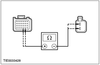
|
4Measure the resistance between: • pin 20 C424 auxiliary restraint system control module, circuit 8-JA49 (white), wiring harness side and pin 2 C420 crash sensor, circuit 8-JA49 (white), wiring harness side; and • pin 21 C424 of the auxiliary restraint system control module, circuit 9-JA49 (brown), wiring harness side and pin 1 C420 of the impact sensor, circuit 9-JA49 (brown), wiring harness side. |
|
• Is the resistance less than 5 ohms in all cases? |
|
|
→ Yes |
|
|
Go to CY2 |
|
|
→ No |
|
|
REPAIR circuits 8-JA49 (white) and 9-JA49 (brown). REPEAT the self-test, CLEAR the DTCs and REACTIVATE the system. For additional information, refer to Supplemental Restraint System of the Air Bags and Seat Belt Pretensioners (SRS) in this section. |
|
|
CY2: CHECK COLLISION SENSOR FOR SHORT TO BATTERY |
|
|
1Enter the ON position. |
|
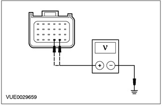
|
2Measure the voltage between: • pin 20 C423 auxiliary restraint system control module, circuit 8-JA49 (white), wiring harness side and ground; and • pin 21 C423 of the auxiliary restraint system control module, electrical circuit 9-JA49 (brown), wiring harness side and ground. |
|
• Is voltage registered? |
|
|
→ Yes |
|
|
REPAIR circuits 8-JA49 (white) and 9-JA49 (brown). REPEAT the self-test, CLEAR the DTCs and REACTIVATE the system. For additional information, refer to Supplemental Restraint System of the Air Bags and Seat Belt Pretensioners (SRS) in this section. |
|
|
→ No |
|
|
Go to CY3 |
|
|
CY3: CHECK COLLISION SENSOR FOR SHORT TO GROUND" |
|
|
1Enter the OFF position. |
|
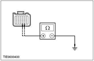
|
2Measure the resistance between: • pin 20 C423 auxiliary restraint system control module, circuit 8-JA49 (white), wiring harness side and ground; and • pin 21 C423 of the auxiliary restraint system control module, electrical circuit 9-JA49 (brown), wiring harness side and ground. |
|
• Is the resistance greater than 10,000 ohms? |
|
|
→ Yes |
|
|
REPEAT the self-test, CLEAR the DTCs, and REACTIVATE the system. For additional information, refer to Supplemental Restraint System (SRS) in this section. |
|
|
→ No |
|
|
REPAIR circuits 8-JA49 (white) and 9-JA49 (brown). REPEAT the self-test, CLEAR the DTCs and REACTIVATE the system. For additional information, refer to Supplemental Restraint System of the Air Bags and Seat Belt Pretensioners (SRS) in this section. |
|
PINPOINT TEST CZ: B2228 DRIVER AIR BAG STAGE 2 CIRCUIT SHORT TO GROUND"
|
STATES |
DETAILS/RESULTS/ACTIONS |
|
CZ1: CHECK RESISTANCE OF DRIVER AIR BAG STAGE 2 CIRCUIT |
|
|
WARNING: Wait at least one minute after disconnecting the battery ground cable before disconnecting any supplemental restraint system electrical connector. Failure to follow this instruction could result in personal injury. |
|
|
1Deactivate the supplemental restraint system. For more information, refer to Supplemental Restraint System Air Bags and Seat Belt Tensioners (SRS) in this section. |
|
|
2Enter the ON position. |
|
|
3Perform a self-test with the simulators installed. |
|
|
• Is the system functioning properly? |
|
|
→ Yes |
|
|
Go to CZ2 |
|
|
→ No |
|
|
Go to CZ3 |
|
|
CZ2: CHECK DRIVER AIR BAG MODULE |
|
|
WARNING: Do not continue this test without the WDS. Failure to follow this instruction may result in injury. |
|
|
1Connect the test and deployment wire to the driver airbag module - stage one. |
|
|
2Select the DMM option in WDS. |
|
|
3Connect the test and deployment wire to the WDS. |
|
|
4Measure the resistance between each terminal and the airbag module housing. |
|
|
5Connect the test and deployment wire to the driver airbag module - stage two. |
|

|
6Measure the resistance between each terminal and the airbag module housing. |
|
• Is the resistance in all cases greater than 10,000 ohms? |
|
|
→ Yes |
|
|
REPEAT the self-test, CLEAR the DTCs, and REACTIVATE the system. For additional information, refer to Supplemental Restraint System (SRS) in this section. |
|
|
→ No |
|
|
INSTALL a new driver air bag module. For additional information, refer to Driver Air Bag Module in this section. REPEAT the self-test, CLEAR the DTCs. REACTIVATE the system. For additional information, refer to Supplemental Restraint System (SRS) in this section. |
|
|
CZ3: CHECK DRIVER AIR BAG STAGE 2 WIRING HARNESS FOR SHORT TO GROUND" |
|
|
1Enter the OFF position. |
|
|
2Disconnect the Supplemental Restraint System Control Module - C424. |
|
|
3Disconnect the Driver Air Bag Module Stage 2 Simulator. |
|
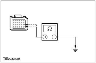
|
4Measure the resistance between: • pin 19 C424 auxiliary restraint system control module, circuit 15S-JA48 (green/black), wiring harness side and ground; and • pin 13 C424 of the auxiliary restraint system control module, circuit 91S- JA48 (black/green), wiring harness side and ground. |
|
5Turn the steering wheel between extreme positions and record the resistance values. |
|
|
• Is the resistance in all cases greater than 10,000 ohms? |
|
|
→ Yes |
|
|
REPEAT the self-test, CLEAR the DTCs, and REACTIVATE the system. For additional information, refer to Supplemental Restraint System (SRS) in this section. |
|
|
→ No |
|
|
Go to CZ4 |
|
|
CZ4: CHECK CLOCK SPRING CIRCUIT FOR SHORT TO GROUND" |
|
|
1Disconnect Clock Spring - C896 or C898. |
|
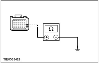
|
2Measure the resistance between: • pin 19 C424 auxiliary restraint system control module, circuit 15S-JA48 (green/black), wiring harness side and ground; and • pin 13 C424 of the auxiliary restraint system control module, circuit 91S- JA48 (black/green), wiring harness side and ground. |
|
• Is the resistance in all cases greater than 10,000 ohms? |
|
|
→ Yes |
|
|
INSTALL a new clock spring. For additional information, refer to Clock Spring in this section. REPEAT the self-test, CLEAR the DTCs. REACTIVATE the system. For additional information, refer to Supplemental Restraint System of the Air Bags and Seat Belt Pretensioners (SRS) in this section. |
|
|
→ No |
|
|
REPAIR circuit 15S-JA48 (GN/BLK) or 91S-JA48 (BLK/GN). REPEAT self-test, CLEAR DTCs, REACTIVATE system. For additional information, refer to Supplemental Restraint System (SRS) in this section. |
|
PINPOINT TEST DA: B2229 PASSENGER AIR BAG STAGE 2 CIRCUIT SHORT TO GROUND"
|
STATES |
DETAILS/RESULTS/ACTIONS |
|
DA1: CHECK PASSENGER AIR BAG STAGE 2 CIRCUIT RESISTANCE |
|
|
WARNING: Wait at least one minute after disconnecting the battery ground cable before disconnecting any supplemental restraint system electrical connector. Failure to follow this instruction could result in personal injury. |
|
|
1Deactivate the supplemental restraint system. For more information, refer to Supplemental Restraint System Air Bags and Seat Belt Tensioners (SRS) in this section. |
|
|
2Enter the ON position. |
|
|
3Perform a self-test with the simulators installed. |
|
|
• Is the system functioning properly? |
|
|
→ Yes |
|
|
Go to DA2 |
|
|
→ No |
|
|
Go to DA3 |
|
|
DA2: CHECK PASSENGER AIR BAG MODULE |
|
|
WARNING: Do not continue this test without WDS. Failure to follow this instruction may result in injury. |
|
|
1Connect the test and deployment wire to the passenger air bag module - stage one. |
|
|
2Select the DMM option in WDS. |
|
|
3Connect the test and deployment wire to the WDS. |
|
|
4Measure the resistance between each terminal and the airbag module housing. |
|
|
5Connect the test and deployment wire to the passenger air bag module - stage two. |
|

|
6Measure the resistance between each terminal and the airbag module housing. |
|
• Is the resistance in all cases greater than 10,000 ohms? |
|
|
→ Yes |
|
|
REPEAT the self-test, CLEAR the DTCs. REACTIVATE the system. For additional information, refer to Supplemental Restraint System (SRS) Air Bags and Seat Belt Tensioners (SRS) in this section. |
|
|
→ No |
|
|
INSTALL a new passenger air bag module. REPEAT the self-test, CLEAR the DTCs. REACTIVATE the system. For additional information, refer to Supplemental Restraint System (SRS) Air Bags and Seat Belt Tensioners (SRS) in this section. |
|
|
DA3: CHECK PASSENGER AIR BAG STAGE 2 WIRING HARNESS FOR SHORT TO GROUND" |
|
|
1Enter the OFF position. |
|
|
2Disconnect the Supplemental Restraint System Control Module - C424. |
|
|
3Disconnect the Passenger Air Bag Module Stage 2 Simulator. |
|
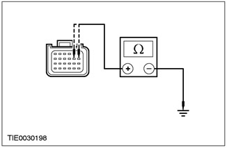
|
4Measure the resistance between: • pin 8 C424 auxiliary restraint system control module, circuit 15S-JA32 (green/yellow), wiring harness side and ground; and • pin 7 C424 of the auxiliary restraint system control module, circuit 91S- JA32 (black/yellow), wiring harness side and ground. |
|
• Is the resistance in all cases greater than 10,000 ohms? |
|
|
→ Yes |
|
|
REPEAT the self-test, CLEAR the DTCs. REACTIVATE the system. For additional information, refer to Supplemental Restraint System (SRS) Air Bags and Seat Belt Tensioners (SRS) in this section. |
|
|
→ No |
|
|
REPAIR circuit 15S-JA32 (green/yellow) or 91S-JA32 (black/yellow). REPEAT self-test, CLEAR DTCs. REACTIVATE the system. For additional information, refer to Supplemental Restraint System (SRS) in this section. |
|
PINPOINT TEST DB: B2230 DRIVER AIR BAG STAGE 2 CIRCUIT SHORT TO BATTERY
|
STATES |
DETAILS/RESULTS/ACTIONS |
|
DB1: CHECK DRIVER STAGE 2 AIR BAG WIRING HARNESS FOR SHORT TO BATTERY OR IGNITION |
|
|
WARNING: Wait at least one minute after disconnecting the battery ground cable before disconnecting any supplemental restraint system electrical connector. Failure to follow this instruction could result in personal injury. |
|
|
1Deactivate the auxiliary restraint system. |
|
|
2Disconnect the Driver Air Bag Module Stage 2 Simulator. |
|
|
3Disconnect the Supplemental Restraint System Control Module - C424. |
|
|
4Enter the ON position. |
|
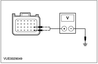
|
5Measure the voltage between: • pin 19 C424 auxiliary restraint system control module, circuit 15S-JA48 (green/black), wiring harness side and ground; and • pin 13 C424 of the auxiliary restraint system control module, circuit 91S- JA48 (black/green), wiring harness side and ground. |
|
• Is voltage registered? |
|
|
→ Yes |
|
|
Go to DB2 |
|
|
→ No |
|
|
CONNECT the driver air bag module stage 2 simulator and the supplemental restraints control module. REPEAT the self-test, CLEAR the DTCs. REACTIVATE the system. |
|
|
DB2: CHECK CLOCK SPRING CIRCUIT FOR SHORT TO BATTERY |
|
|
1Enter the OFF position. |
|
|
2Disconnect Driver Airbag Wiring Harness - C921. |
|
|
3Enter the ON position. |
|
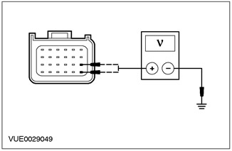
|
4Measure the voltage between: • pin 19 C424 auxiliary restraint system control module, circuit 15S-JA48 (green/black) wiring harness side and ground; and • pin 13 C424 of the auxiliary restraint system control module, circuit 91S-JA48 (black/green) on the wiring harness side and ground. |
|
5Turn the steering wheel between extreme positions and record the resistance values. |
|
|
• Is voltage registered? |
|
|
→ Yes |
|
|
Go to DB3 |
|
|
→ No |
|
|
INSTALL a new airbag wiring harness. REPEAT the self-test, CLEAR the DTCs. REACTIVATE the system. |
|
|
DB3: CHECK CLOCK SPRING CIRCUIT FOR SHORT TO BATTERY OR IGNITION |
|
|
1Enter the OFF position. |
|
|
2Disconnect Clock Spring - C896 or C898. |
|
|
3Enter the ON position. |
|

|
4Measure the voltage between: • pin 19 C424 auxiliary restraint system control module, circuit 15S-JA48 (green/black), wiring harness side and ground; and • pin 13 C424 of the auxiliary restraint system control module, circuit 91S- JA48 (black/green), wiring harness side and ground. |
|
• Is voltage registered? |
|
|
→ Yes |
|
|
REPAIR circuit 15S-JA48 (Green/Black) or 91S-JA48 (Black/Green). REPEAT self-test, CLEAR DTCs, REACTIVATE system. |
|
|
→ No |
|
|
INSTALL a new clock spring. For additional information, refer to Clock Spring in this section. REPEAT the self-test, CLEAR the DTCs. REACTIVATE the system. |
|
PINPOINT TEST DC: B2231 PASSENGER AIR BAG STAGE 2 CIRCUIT SHORT TO BATTERY
|
STATES |
DETAILS/RESULTS/ACTIONS |
|
DC1: CHECK PASSENGER AIR BAG STAGE 2 WIRING HARNESS FOR SHORT TO BATTERY OR IGNITION |
|
|
WARNING: Wait at least one minute after disconnecting the battery ground cable before disconnecting any supplemental restraint system electrical connector. Failure to follow this instruction could result in personal injury. |
|
|
1Deactivate the auxiliary restraint system. |
|
|
2Disconnect the Passenger Air Bag Module Stage 2 Simulator. |
|
|
3Disconnect the Supplemental Restraint System Control Module - C424. |
|
|
4Enter the ON position. |
|
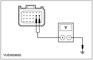
|
5Measure the voltage between: • pin 8 C424 auxiliary restraint system control module, circuit 15S-JA32 (green/yellow), wiring harness side and ground; and • pin 7 C424 of the auxiliary restraint system control module, circuit 91S- JA32 (black/yellow), wiring harness side and ground. |
|
• Is voltage registered? |
|
|
→ Yes |
|
|
REPAIR circuit 15S-JA32 (green/yellow) or 91S-JA32 (black/yellow). REPEAT self-test, CLEAR DTCs, REACTIVATE system. |
|
|
→ No |
|
|
CONNECT the passenger air bag module stage 2 simulator and the supplemental restraints control module. REPEAT the self-test, CLEAR the DTCs, REACTIVATE the system. |
|
PINPOINT TEST DD: B2232 DRIVER AIR BAG STAGE 2 CIRCUIT OPEN
|
STATES |
DETAILS/RESULTS/ACTIONS |
|
DD1: CHECK RESISTANCE OF DRIVER AIR BAG STAGE 2 CIRCUIT |
|
|
WARNING: Wait at least one minute after disconnecting the battery ground cable before disconnecting any supplemental restraint system electrical connector. Failure to follow this instruction could result in personal injury. |
|
|
1Deactivate the auxiliary restraint system. |
|
|
2Enter the ON position. |
|
|
3Perform a self-test with the simulators installed. |
|
|
• Is the system functioning properly? |
|
|
→ Yes |
|
|
Go to DD2 |
|
|
→ No |
|
|
Go to DD3 |
|
|
DD2: CHECK RESISTANCE OF DRIVER AIR BAG MODULE IGNITOR |
|
|
WARNING: Do not continue this test without the WDS. Failure to follow this instruction may result in injury. |
|
|
1Connect the test and deployment wire to the driver airbag module - stage one. |
|
|
2Select the DMM option in WDS. |
|
|
3Connect the test and deployment wire to the WDS. |
|
|
4Measure the resistance of the air bag module igniter circuit. |
|
|
5Connect the test and deployment wire to the driver airbag module - stage two. |
|

|
6Measure the resistance of the air bag module igniter circuit. |
|
• Are the resistance values between 2 and 3 ohms? |
|
|
→ Yes |
|
|
REPEAT the self-test, CLEAR the DTCs, REACTIVATE the system. |
|
|
→ No |
|
|
INSTALL a new driver air bag module. For additional information, refer to Driver Air Bag Module in this section. REPEAT the self-test, CLEAR the DTCs. REACTIVATE the system. |
|
|
DD3: CHECK AIR BAG WIRING HARNESS FOR OPEN OR HIGH RESISTANCE |
|
|
1Enter the OFF position. |
|
|
2Disconnect the Air Bag Module Wiring Harness - C921. |
|

|
3Measure the resistance between: • pin 19 C424 of the auxiliary restraint system control module, circuit 15S-JA48 (green/black) and pin 1 C921 of the clock spring harness, circuit 15S-JA48 (green/black) on the component side; and • pin 13 C424 of the auxiliary restraint system control module, circuit 91S-JA48 (black/green) and pin 2 C921 of the clock spring wiring harness, circuit 91S-JA48 (black/green) on the component side. |
|
4Turn the steering wheel between extreme positions and record the resistance values. |
|
|
• Is the resistance less than 5 ohms in all cases? |
|
|
→ Yes |
|
|
INSTALL a new airbag wiring harness. REPEAT the self-test, CLEAR the DTCs. REACTIVATE the system. |
|
|
→ No |
|
|
Go to DD4 |
|
|
DD4: CHECK CLOCK SPRING CIRCUIT FOR OPEN OR HIGH RESISTANCE |
|
|
1Disconnect the Supplemental Restraint System Control Module - C424. |
|
|
2Disconnect Clock Spring - C896 or C898. |
|
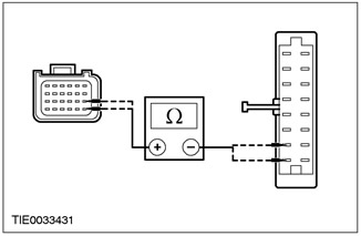
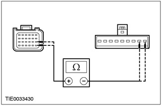
|
3Measure the resistance between: Vehicles with stability control • pin 19 C424 auxiliary restraint system control module, circuit 15S-JA48 (green/black), wiring harness side and pin 1 C898 clock spring, circuit 15S-JA48 (green/black), wiring harness side; and • pin 13 C424 of the auxiliary restraint system control module, circuit 91S-JA48 (black/green), wiring harness side and pin 2 C898 of the clock spring, circuit 91S-JA48 (black/green), wiring harness side. |
|
Vehicles without stability control. • pin 19 C424 auxiliary restraint system control module, circuit 15S-JA48 (green/black), wiring harness side and pin 1 C896 clock spring, circuit 15S-JA48 (green/black), wiring harness side; and • pin 13 C424 of the auxiliary restraint system control module, circuit 91S-JA48 (black/green), wiring harness side and pin 2 C896 of the clock spring, circuit 91S-JA8 (black/green), wiring harness side. |
|
|
• Is the resistance less than 5 ohms in all cases? |
|
|
→ Yes |
|
|
INSTALL a new clock spring. For additional information, refer to Clock Spring in this section. REPEAT the self-test, CLEAR the DTCs. REACTIVATE the system. |
|
|
→ No |
|
|
REPAIR circuit 15S-JA48 (Green/Black) or 91S-JA48 (Black/Green). REPEAT self-test, CLEAR DTCs. REACTIVATE system. |
|
PINPOINT TEST DE: B2233 PASSENGER AIR BAG STAGE 2 CIRCUIT OPEN
|
STATES |
DETAILS/RESULTS/ACTIONS |
|
DE1: CHECK PASSENGER AIR BAG STAGE 2 CIRCUIT RESISTANCE |
|
|
WARNING: Wait at least one minute after disconnecting the battery ground cable before disconnecting any supplemental restraint system electrical connector. Failure to follow this instruction could result in personal injury. |
|
|
1Deactivate the auxiliary restraint system. |
|
|
2Enter the ON position. |
|
|
3Perform a self-test with the simulators installed. |
|
|
• Is the system functioning properly? |
|
|
→ Yes |
|
|
Go to DE2 |
|
|
→ No |
|
|
REPAIR circuits 15S-JA32 (green/yellow) and 91S-JA32 (black/yellow). REPEAT self-test, CLEAR DTCs and REACTIVATE the system. |
|
|
DE2: CHECK RESISTANCE OF PASSENGER AIR BAG MODULE IGNITOR CIRCUIT |
|
|
WARNING: Do not continue this test without the WDS. Failure to follow this instruction may result in injury. |
|
|
1Connect the test and deployment wire to the passenger air bag module - stage one. |
|
|
2Select the DMM option in WDS. |
|
|
3Connect the test and deployment wire to the WDS. |
|
|
4Measure the resistance of the air bag module igniter circuit. |
|
|
5Connect the test and deployment wire to the passenger air bag module - stage two. |
|

|
6Measure the resistance of the air bag module igniter circuit. |
|
• Are the resistance values between 2 and 3 ohms? |
|
|
→ Yes |
|
|
REPEAT the self-test, CLEAR the DTCs, REACTIVATE the system. |
|
|
→ No |
|
|
INSTALL a new passenger air bag module. REPEAT the self-test, CLEAR the DTCs. REACTIVATE the system. |
|
PINPOINT TEST DF: B2234 DRIVER AIR BAG STAGE 2 CIRCUIT LOW RESISTANCE
|
STATES |
DETAILS/RESULTS/ACTIONS |
|
DF1: CHECK RESISTANCE OF DRIVER AIR BAG STAGE 2 CIRCUIT |
|
|
WARNING: Wait at least one minute after disconnecting the battery ground cable before disconnecting any supplemental restraint system electrical connector. Failure to follow these instructions could result in personal injury. |
|
|
1Deactivate the auxiliary restraint system. |
|
|
2Enter the ON position. |
|
|
3Perform a self-test with the simulators installed. |
|
|
• Is the system functioning properly? |
|
|
→ Yes |
|
|
Go to DF2 |
|
|
→ No |
|
|
Go to DF3 |
|
|
DF2: CHECK RESISTANCE OF DRIVER AIR BAG MODULE IGNITOR |
|
|
1Connect the test and deployment wire to the driver airbag module - stage one. |
|
|
2Select the DMM option in WDS. |
|
|
3Connect the test and deployment wire to the WDS. |
|
|
4Measure the resistance of the air bag module igniter circuit. |
|
|
5Connect the test and deployment wire to the driver airbag module - stage two. |
|

|
6Measure the resistance of the air bag module igniter circuit. |
|
• Are the resistance values between 2 and 3 ohms? |
|
|
→ Yes |
|
|
REPEAT the self-test, CLEAR the DTCs, REACTIVATE the system. |
|
|
→ No |
|
|
INSTALL a new driver air bag module. For additional information, refer to Driver Air Bag Module in this section. REPEAT the self-test, CLEAR the DTCs. REACTIVATE the system. |
|
|
DF3: CHECK AIR BAG WIRING HARNESS FOR LOW RESISTANCE |
|
|
1Enter the OFF position. |
|
|
2Disconnect the Air Bag Module Wiring Harness - C921. |
|
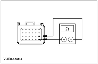
|
3Measure the resistance between the supplemental restraint system control module C424 pin 19, circuit 15S-JA48 (GN/BLK) and pin 13, circuit 91S-JA48 (BLK/GN), wiring harness side. |
|
4Turn the steering wheel between extreme positions and record the resistance values. |
|
|
• Is the resistance greater than 10,000 ohms? |
|
|
→ Yes |
|
|
INSTALL a new airbag wiring harness. REPEAT the self-test, CLEAR the DTCs. REACTIVATE the system. |
|
|
→ No |
|
|
Go to DF4 |
|
|
DF4: CHECK CLOCK SPRING CIRCUIT FOR LOW RESISTANCE |
|
|
1Disconnect Clock Spring - C896 or C898. |
|
|
2Disconnect the Supplemental Restraint System Control Module - C424. |
|

|
3Measure the resistance between secondary restraint system control module C424 pin 19, circuit 15S-JA48 (GN/BLK), harness side and pin 13, circuit 91S-JA48 (BLK/GRN), harness side. |
|
• Is the resistance greater than 10,000 ohms? |
|
|
→ Yes |
|
|
INSTALL a new clock spring. For additional information, refer to Clock Spring in this section. REPEAT the self-test, CLEAR the DTCs. REACTIVATE the system. |
|
|
→ No |
|
|
REPAIR circuits 15S-JA48 (green/black) and 91S-JA48 (black/green). REPEAT self-test, CLEAR DTCs and REACTIVATE the system. |
|
PINPOINT TEST DG: B2235 PASSENGER AIR BAG STAGE 2 CIRCUIT LOW RESISTANCE
|
STATES |
DETAILS/RESULTS/ACTIONS |
|
DG1: CHECK PASSENGER AIR BAG STAGE 2 CIRCUIT RESISTANCE |
|
|
WARNING: Wait at least one minute after disconnecting the battery ground cable before disconnecting any supplemental restraint system electrical connector. Failure to follow these instructions could result in personal injury. |
|
|
1Deactivate the auxiliary restraint system. |
|
|
2Enter the ON position. |
|
|
3Perform a self-test with the simulators installed. |
|
|
• Is the system functioning properly? |
|
|
→ Yes |
|
|
Go to DG2 |
|
|
→ No |
|
|
Go to DG3 |
|
|
DG2: CHECK RESISTANCE OF PASSENGER AIR BAG MODULE IGNITOR CIRCUIT |
|
|
1Connect the test and deployment wire to the passenger air bag module - stage one. |
|
|
2Select the DMM option in WDS. |
|
|
3Connect the test and deployment wire to the WDS. |
|
|
4Measure the resistance of the air bag module igniter circuit. |
|
|
5Connect the test and deployment wire to the passenger air bag module - stage two. |
|

|
6Measure the resistance of the air bag module igniter circuit. |
|
• Are the resistance values between 2 and 3 ohms? |
|
|
→ Yes |
|
|
REPEAT the self-test, CLEAR the DTCs, REACTIVATE the system. |
|
|
→ No |
|
|
INSTALL a new passenger air bag module. REPEAT the self-test, CLEAR the DTCs. REACTIVATE the system. |
|
|
DG3: CHECK PASSENGER AIR BAG STAGE 2 WIRING HARNESS FOR LOW RESISTANCE |
|
|
1Enter the OFF position. |
|
|
2Disconnect the Passenger Air Bag Module Stage 2 Simulator. |
|
|
3Disconnect the Supplemental Restraint System Control Module - C424. |
|

|
4Measure the resistance between secondary restraint system control module C424 pin 8, circuit 15S-JA32 (GN/YE), harness side and pin 7, circuit 91S-JA32 (BK/YE), harness side. |
|
• Is the resistance greater than 10,000 ohms? |
|
|
→ Yes |
|
|
REPEAT the self-test, CLEAR the DTCs, REACTIVATE the system. |
|
|
→ No |
|
|
REPAIR circuits 15S-JA32 (green/yellow) and 91S-JA32 (black/yellow). REPEAT self-test, CLEAR DTCs and REACTIVATE the system. |
|
PINPOINT TEST DH: DTC B2477: AIR BAG CONTROL MODULE CONFIGURATION ERROR
|
STATES |
DETAILS/RESULTS/ACTIONS |
|
DH1: CHECK ACCESSORY RESTRAINT CONTROL MODULE GROUND CIRCUIT |
|
|
WARNING: Wait at least one minute after disconnecting the battery ground cable before disconnecting any supplemental restraint system electrical connector. Failure to follow these instructions could result in personal injury. |
|
|
1Deactivate the auxiliary restraint system. |
|
|
2Disconnect the Supplemental Restraint System Control Module - C424. |
|
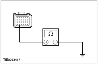
|
3Measure the resistance between secondary restraint system control module C424 pin 23, circuit 91-JA10 (BK/RD), wiring harness side and ground. |
|
• Is the resistance less than 5 ohms? |
|
|
→ Yes |
|
|
INSTALL a new Supplemental Restraint System Control Module. REPEAT the self-test, CLEAR the DTCs. REACTIVATE the system. |
|
|
→ No |
|
|
REPAIR circuit 91-JA10 (black/red). REPEAT self-test, CLEAR DTCs. REACTIVATE system. |
|
PINPOINT TEST DI: DTC B2852: RIGHT SIDE IMPACT SENSOR SHORT TO GROUND OR BATTERY
|
STATES |
DETAILS/RESULTS/ACTIONS |
|
DI1: CHECK COLLISION SENSOR CIRCUIT |
|
|
WARNING: Wait at least one minute after disconnecting the battery ground cable before disconnecting any supplemental restraint system electrical connector. Failure to follow this instruction could result in personal injury. |
|
|
1Deactivate the auxiliary restraint system. |
|
|
2Disconnect Right Side Impact Sensor - C428. |
|
|
3Disconnect the Supplemental Restraint System Control Module - C423. |
|

|
4Measure the resistance between: • pin 40 C423 of the auxiliary restraint system control module, circuit 8-JA40 (WH/VIA), harness side and pin 2 C428 of the right side impact sensor, circuit 8-JA40 (WH/VIA), harness side; and • pin 39 C423 of the secondary restraint system control module, circuit 9-JA40 (brown/white), wiring harness side and pin 1 C428 of the right side impact sensor, circuit 9-JA40 (brown/white), wiring harness side. |
|
• Is the resistance less than 5 ohms in all cases? |
|
|
→ Yes |
|
|
Go to DI2 |
|
|
→ No |
|
|
REPAIR circuit 8-JA40 (white/purple) or circuit 9-JA40 (brown/white). REPEAT self-test, CLEAR DTCs. REACTIVATE the system. |
|
|
DI2: CHECK COLLISION SENSOR FOR SHORT TO BATTERY |
|
|
1Enter the ON position. |
|
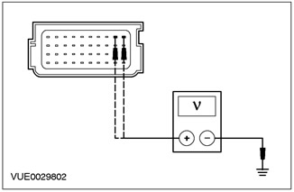
|
2Measure the voltage between: • pin 40 C423 auxiliary restraint system control module, circuit 8-JA40 (white/purple), wiring harness side and ground; and • pin 39 C423 auxiliary restraint system control module, circuit 9-JA49 (brown/white), wiring harness side and ground" |
|
• Is voltage registered? |
|
|
→ Yes |
|
|
REPAIR circuit 8-JA40 (white/purple) or circuit 9-JA40 (brown/white). REPEAT self-test, CLEAR DTCs, REACTIVATE system. |
|
|
→ No |
|
|
Go to DI3 |
|
|
DI3: CHECK COLLISION SENSOR FOR SHORT TO GROUND" |
|
|
1Enter the OFF position. |
|
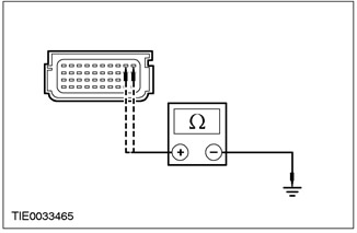
|
2Measure the resistance between: • pin 40 C423 auxiliary restraint system control module, circuit 8-JA40 (white/purple), wiring harness side and ground; and • pin 39 C423 auxiliary restraint system control module, circuit 9-JA49 (brown/white), wiring harness side and ground" |
|
• Is the resistance in all cases greater than 10,000 ohms? |
|
|
→ Yes |
|
|
REPEAT the self-test, CLEAR the DTCs, REACTIVATE the system. |
|
|
→ No |
|
|
REPAIR circuit 8-JA40 (white/purple) or circuit 9-JA40 (brown/white). REPEAT self-test, CLEAR DTCs, REACTIVATE system. |
|
PINPOINT TEST DJ: DTC B2853: LEFT SIDE IMPACT SENSOR SHORT TO GROUND OR BATTERY
|
STATES |
DETAILS/RESULTS/ACTIONS |
|
DJ1: CHECK COLLISION SENSOR CIRCUIT |
|
|
WARNING: Wait at least one minute after disconnecting the battery ground cable before disconnecting any supplemental restraint system electrical connector. Failure to do so could result in personal injury. |
|
|
1Deactivate the auxiliary restraint system. |
|
|
2Disconnect Left Side Impact Sensor - C427. |
|
|
3Disconnect the Supplemental Restraint System Control Module - C423. |
|
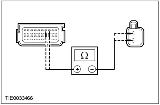
|
4Measure the resistance between: • pin 38 C423 auxiliary restraint system control module, circuit 8-JA39 (white), wiring harness side and pin 2 C427 left side impact sensor, circuit 8-JA39 (white), wiring harness side; and • pin 37 C423 of the auxiliary restraint system control module, circuit 9-JA39 (brown), wiring harness side and pin 1 C427 of the frontal impact sensor, circuit 9-JA39 (brown), wiring harness side. |
|
• Is the resistance less than 5 ohms in all cases? |
|
|
→ Yes |
|
|
Go to DJ2 |
|
|
→ No |
|
|
REPAIR circuit 8-JA39 (white) or circuit 9-JA39 (brown). REPEAT self-test, CLEAR DTCs. REACTIVATE the system. |
|
|
DJ2: CHECK COLLISION SENSOR FOR SHORT TO BATTERY |
|
|
1Enter the ON position. |
|
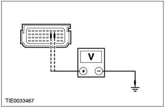
|
2Measure the voltage between: • pin 38 C423 auxiliary restraint system control module, circuit 8-JA39 (white), wiring harness side and ground; and • pin 37 C423 auxiliary restraint system control module, circuit 9-JA39 (brown), wiring harness side and ground" |
|
• Is voltage registered? |
|
|
→ Yes |
|
|
REPAIR circuit 8-JA39 (white) or circuit 9-JA39 (brown). REPEAT self-test, CLEAR DTCs, REACTIVATE system. |
|
|
→ No |
|
|
Go to DJ3 |
|
|
DJ3: CHECK COLLISION SENSOR FOR SHORT TO GROUND" |
|
|
1Enter the OFF position. |
|
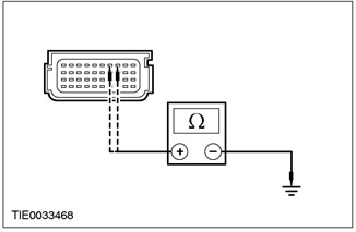
|
2Measure the resistance between: • pin 38 C423 auxiliary restraint system control module, circuit 8-JA39 (white), wiring harness side and ground; and • pin 37 C423 of the auxiliary restraint system control module, electrical circuit 9-JA39 (brown), wiring harness side and ground. |
|
• Is the resistance in all cases greater than 10,000 ohms? |
|
|
→ Yes |
|
|
REPEAT the self-test, CLEAR the DTCs, REACTIVATE the system. |
|
|
→ No |
|
|
REPAIR circuit 8-JA39 (white) or circuit 9-JA39 (brown). REPEAT self-test, CLEAR DTCs, REACTIVATE system. |
|
PINPOINT TEST DK: DTC B2855: FRONT IMPACT SENSOR SHORT TO GROUND OR BATTERY
|
STATES |
DETAILS/RESULTS/ACTIONS |
|
DK1: CHECK COLLISION SENSOR CIRCUIT |
|
|
WARNING: Wait at least one minute after disconnecting the battery ground cable before disconnecting any supplemental restraint system electrical connector. Failure to do so could result in personal injury. |
|
|
1Deactivate the auxiliary restraint system. |
|
|
2Disconnect the Front Impact Sensor - C420. |
|
|
3Disconnect the Supplemental Restraint System Control Module - C424. |
|

|
4Measure the resistance between: • pin 20 C424 auxiliary restraint system control module, circuit 8-JA49 (white), wiring harness side and pin 2 C420 frontal impact sensor, circuit 8-JA49 (white), wiring harness side; and • pin 21 C424 of the auxiliary restraint system control module, circuit 9-JA49 (brown), wiring harness side and pin 1 C420 of the frontal impact sensor, circuit 9-JA49 (brown), wiring harness side. |
|
• Is the resistance less than 5 ohms in all cases? |
|
|
→ Yes |
|
|
Go to DK2 |
|
|
→ No |
|
|
REPAIR circuit 8-JA49 (white) or circuit 9-JA49 (brown). REPEAT self-test, CLEAR DTCs. REACTIVATE the system. |
|
|
DK2: CHECK COLLISION SENSOR FOR SHORT TO BATTERY |
|
|
1Enter the ON position. |
|
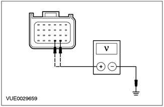
|
2Measure the voltage between: • pin 20 C424 auxiliary restraint system control module, circuit 8-JA49 (white), wiring harness side and ground; and • pin 21 C424 auxiliary restraint system control module, circuit 9-JA49 (brown), wiring harness side and ground" |
|
• Is voltage registered? |
|
|
→ Yes |
|
|
REPAIR circuit 8-JA49 (white) or circuit 9-JA49 (brown) and circuit 15-JA10 (green/orange). REPEAT self-test, CLEAR DTCs REACTIVATE system. |
|
|
→ No |
|
|
Go to DK3 |
|
|
DK3: CHECK COLLISION SENSOR FOR SHORT TO GROUND" |
|
|
1Enter the OFF position. |
|
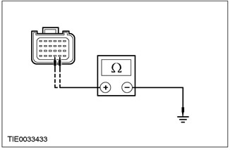
|
2Measure the resistance between: • pin 20 C424 auxiliary restraint system control module, circuit 8-JA49 (white), wiring harness side and ground; and • pin 21 C424 auxiliary restraint system control module, circuit 9-JA49 (brown), wiring harness side and ground" |
|
• Is the resistance in all cases greater than 10,000 ohms? |
|
|
→ Yes |
|
|
REPEAT the self-test, CLEAR the DTCs, REACTIVATE the system. |
|
|
→ No |
|
|
REPAIR circuit 8-JA49 (white) or circuit 9-JA49 (brown). REPEAT self-test, CLEAR DTCs, REACTIVATE system. |
|
PINPOINT TEST DL: U2027 LEFT SIDE IMPACT SENSOR COMMUNICATION ERROR
|
STATES |
DETAILS/RESULTS/ACTIONS |
|
DL1: CHECK COLLISION SENSOR CIRCUIT |
|
|
WARNING: Wait at least one minute after disconnecting the battery ground cable before disconnecting any supplemental restraint system electrical connector. Failure to follow this instruction could result in personal injury. |
|
|
1Deactivate the auxiliary restraint system. |
|
|
2Disconnect Left Side Impact Sensor - C427. |
|
|
3Disconnect the Supplemental Restraint System Control Module - C423. |
|

|
4Measure the resistance between: • pin 38 C423 auxiliary restraint system control module, circuit 8-JA39 (white), wiring harness side and pin 2 C427 left side impact sensor, circuit 8-JA39 (white), wiring harness side; and • pin 37 C423 of the auxiliary restraint system control module, circuit 9-JA39 (brown), wiring harness side and pin 1 C427 of the left side impact sensor, circuit 9-JA39 (brown), wiring harness side. |
|
• Is the resistance less than 5 ohms in all cases? |
|
|
→ Yes |
|
|
REPEAT the self-test, CLEAR the DTCs, REACTIVATE the system. |
|
|
→ No |
|
|
REPAIR circuit 8-JA40 (white/purple) or circuit 9-JA40 (brown/white). REPEAT self-test, CLEAR DTCs. REACTIVATE the system. |
|
PINPOINT TEST DM: U2028 RIGHT SIDE IMPACT SENSOR COMMUNICATION ERROR
|
STATES |
DETAILS/RESULTS/ACTIONS |
|
DM1: CHECK COLLISION SENSOR CIRCUIT |
|
|
WARNING: Wait at least one minute after disconnecting the battery ground cable before disconnecting any supplemental restraint system electrical connector. Failure to follow this instruction could result in personal injury. |
|
|
1Deactivate the auxiliary restraint system. |
|
|
2Disconnect Right Side Impact Sensor - C428. |
|
|
3Disconnect the Supplemental Restraint System Control Module - C423. |
|

|
4Measure the resistance between: • pin 40 C423 of the auxiliary restraint system control module, circuit 8-JA40 (WH/VIA), harness side and pin 2 C428 of the right side impact sensor, circuit 8-JA40 (WH/VIA), harness side; and • pin 39 C423 of the secondary restraint system control module, circuit 9-JA40 (brown/white), wiring harness side and pin 1 C428 of the right side impact sensor, circuit 9-JA40 (brown/white), wiring harness side. |
|
• Is the resistance less than 5 ohms in all cases? |
|
|
→ Yes |
|
|
REPEAT the self-test, CLEAR the DTCs, REACTIVATE the system. |
|
|
→ No |
|
|
REPAIR circuit 8-JA39 (white) or circuit 9-JA39 (brown). REPEAT self-test, CLEAR DTCs. REACTIVATE the system. |
|