PINPOINT TEST AJ: NO CONNECTION WITH MODULE
|
STATES |
DETAILS/RESULTS/ACTIONS |
|
AJ1: CHECKING WDS DATA TRANSMISSION VIA DATA LINK CONNECTOR (DLC) |
|
|
1Please select an alternate system to check out the DLC. |
|
|
• Is WDS able to communicate with the selected system? |
|
|
→ Yes |
|
|
Go to AJ2 |
|
|
→ No |
|
|
CHECK DLC. For more information, refer to the Wiring Diagrams. |
|
|
AJ2: CHECKING THE AIR BAG WARNING LAMP |
|
|
1Enter the ON position. |
|
|
2The airbag warning light should come on for three seconds with the ignition switch in the ON position and then go out. If a fault is present, the airbag warning light will begin to flash after five seconds. |
|
|
• Does the airbag indicator light work? |
|
|
→ Yes |
|
|
Go to AJ3 |
|
|
→ No |
|
|
CHECK the instrument cluster. For more information, refer to the Wiring Diagrams. |
|
|
AJ3: CHECKING THE DLC ELECTRICAL CIRCUIT |
|
|
WARNING: Wait at least one minute after disconnecting the battery ground cable before disconnecting any auxiliary restraint system connector. Failure to follow this instruction could result in injury. |
|
|
1Enter the OFF position. |
|
|
2Deactivate the supplemental restraint system. For more information, refer to Supplemental Restraint System Air Bags and Seat Belt Tensioners (SRS) in this section. |
|
|
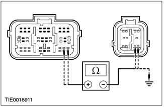
3Disconnect C424 Air Bag Control Module. |
|
|
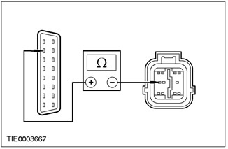
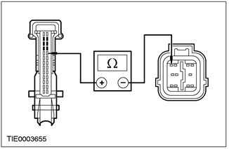
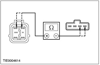
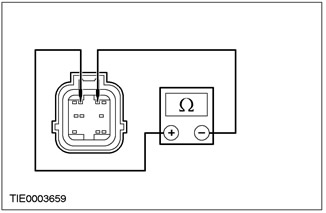
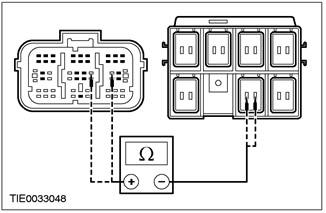
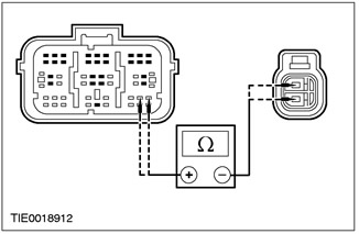
4Measure the resistance between DLC pin 7 C200, circuit 8-EE18 (WH/BLK) and air bag control module pin 7 C424, circuit 8-EE7 (WH/RED), harness side. |
|
• Resistance less than 5 ohms? |
|
|
→ Yes |
|
|
INSTALL a new air bag control module. REPEAT the self-test, CLEAR the DTCs. REACTIVATE the system. For additional information, refer to Supplemental Restraint System (SRS) Air Bags and Seat Belt Pretensioners (SRS) in this section. |
|
|
→ No |
|
|
REPAIR circuit 8-EE18 (WH/BLK)/8-EE7 (WH/RED). REPEAT self-test, CLEAR DTCs. REACTIVATE system. For additional information, refer to Supplemental Restraint System (SRS) Air Bags and Seat Belt Tensioners (SRS) in this section. |
|
PINPOINT TEST AK: DTC B1921: AIR BAG LAMP GROUND CIRCUIT OPEN
|
STATES |
DETAILS/RESULTS/ACTIONS |
|
AK1: CHECKING THE AIR BAG CONTROL MODULE MOUNTING |
|
|
WARNING: Wait at least one minute after disconnecting the battery ground cable before disconnecting any auxiliary restraint system connector. Failure to follow this instruction could result in injury. |
|
|
1Deactivate the supplemental restraint system. For more information, refer to Supplemental Restraint System Air Bags and Seat Belt Tensioners (SRS) in this section. |
|
|
2Remove the floor console. For additional information, refer to Section 501-12. |
|
|
3Check the airbag control module mounting. |
|
|
• Is the air bag control module properly installed and all bolts tightened to the specified torque? |
|
|
→ Yes |
|
|
Go to AK2 |
|
|
→ No |
|
|
LOCK the air bag control module. REPEAT the self-test, CLEAR the DTCs. RE-ACTIVATE the system. For additional information, refer to Supplemental Restraint System (SRS) Air Bags and Seat Belt Pretensioners (SRS) in this section. |
|
|
AK2: CHECKING THE AIR BAG CONTROL MODULE HOUSING GROUND |
|
|
1Disconnect C424 Air Bag Control Module. |
|
|
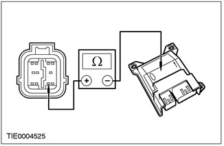
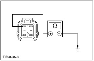
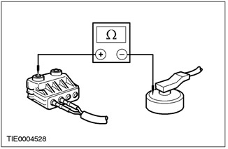
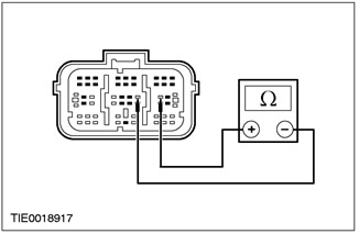
2Measure the resistance between pin 9 C424 of the air bag control module, circuit 91-JA10 (BK/RD), harness side and the air bag control module housing. |
|
• Resistance less than 5 ohms? |
|
|
→ Yes |
|
|
REPEAT the self-test. CLEAR the DTCs. RE-ACTIVATE the system. For additional information, refer to Supplemental Restraint System (SRS) Air Bags and Seat Belt Tensioners (SRS) in this section. |
|
|
→ No |
|
|
REMOVE the air bag control module. CLEAN the air bag control module support (including bolts). INSTALL the air bag control module. REPEAT the self-test, CLEAR the DTCs. REACTIVATE the system. For additional information, refer to Supplemental Restraint System (SRS) Air Bags and Seat Belt Pretensioners (SRS) in this section. |
|
PINPOINT TEST AL: DTC B1318: LOW BATTERY VOLTAGE
|
STATES |
DETAILS/RESULTS/ACTIONS |
|
AL1: CHECK BATTERY VOLTAGE |
|
|
1Enter the ON position. |
|
|
2Check the battery voltage with the ignition switch in the on position. |
|
|
• Is the battery voltage greater than 9V? |
|
|
→ Yes |
|
|
Go to AL2 |
|
|
→ No |
|
|
CHECK the battery and charging system. Refer to Section 414-00 for additional information. REPEAT the self-test. CLEAR the DTCs. |
|
|
AL2: CHECKING THE CONDITION OF THE FUSE. |
|
|
1Enter the OFF position. |
|
|
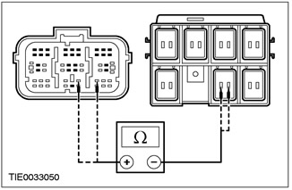
2Disconnect Fuse 60 (7.5A). |
|
|
3CHECK Fuse 60 (7.5A). |
|
|
4Check the condition of fuse 60 (7.5 A). |
|
|
• Is there corrosion on the fuse or terminals? |
|
|
→ Yes |
|
|
CLEAN the terminals. INSTALL a new 60 (7.5 A) fuse. REPEAT the self-test, CLEAR the DTCs. |
|
|
→ No |
|
|
Go to AL3 |
|
|
AL3: CHECK THE AIR BAG CONTROL MODULE POWER SUPPLY CIRCUIT |
|
|
WARNING: Wait at least one minute after disconnecting the battery ground cable before disconnecting any auxiliary restraint system connector. Failure to follow this instruction could result in injury. |
|
|
1Deactivate the supplemental restraint system. For more information, refer to Supplemental Restraint System Air Bags and Seat Belt Tensioners (SRS) in this section. |
|
|
2Disconnect C424 Air Bag Control Module. |
|
|
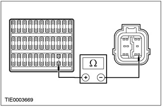
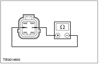
3Measure the resistance between fuse 60 (7.5A) output and pin 8 C424 of the air bag control module, circuit 15-JA10 (green/orange), harness side. |
|
• Resistance less than 5 ohms? |
|
|
→ Yes |
|
|
Go to AL4 |
|
|
→ No |
|
|
CHECK the connector terminals for corrosion or dirt. REPEAT the self-test. CLEAR the DTCs. REACTIVATE the system. For additional information, refer to Supplemental Restraint System of the Air Bags and Seat Belt Pretensioners (SRS) in this section. |
|
|
AL4: CHECK THE AIR BAG CONTROL MODULE GROUND CIRCUIT |
|
|
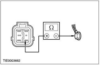
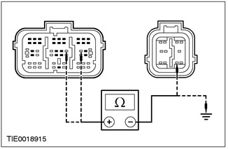
1Measure the resistance between pin 9 C424 of the air bag control module, circuit 91-JA10 (BK/RD), harness side and ground G41 on the A-pillar. |
|
• Resistance less than 2 ohms? |
|
|
→ Yes |
|
|
REPEAT the self-test, CLEAR the DTCs. RE-ACTIVATE the system. For additional information, refer to Supplemental Restraint System (SRS) Air Bags and Seat Belt Tensioners (SRS) in this section. |
|
|
→ No |
|
|
CHECK ground point G41 on the A-pillar for the air bag control module for looseness and corrosion. REPEAT the self-test, CLEAR the DTCs. REACTIVATE the system. For additional information, refer to Supplemental Restraint System (SRS) Air Bags and Seat Belt Pretensioners (SRS) in this section. |
|
PINPOINT TEST AM: DTC B1869: AIR BAG WARRANTY LAMP CIRCUIT OPEN OR SHORT TO GROUND.
|
STATES |
DETAILS/RESULTS/ACTIONS |
|
AM1: CHECK AIR BAG WARNING LAMP. |
|
|
1Enter the ON position. |
|
|
2Check the airbag warning light. |
|
|
• Is the airbag indicator light on continuously? |
|
|
→ Yes |
|
|
Go to AM2 |
|
|
→ No |
|
|
Go to AM4 |
|
|
AM2: CHECKING THE AIR BAG WARRANTY LAMP CIRCUIT |
|
|
WARNING: Wait at least one minute after disconnecting the battery ground cable before disconnecting any auxiliary restraint system connector. Failure to follow this instruction could result in injury. |
|
|
1Enter the OFF position. |
|
|
2Deactivate the supplemental restraint system. For more information, refer to Supplemental Restraint System Air Bags and Seat Belt Tensioners (SRS) in this section. |
|
|
3Disconnect C424 Air Bag Control Module. |
|
|
4Disconnect C809 instrument cluster. |
|
|
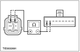
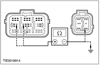
5Measure the resistance between pin 22 C809 instrument cluster, circuit 91S-JA14 (GN/BLK), harness side and pin 4 C424 air bag control module, circuit 91S-JA14 (GN/BLK), harness side. |
|
• Resistance less than 5 ohms? |
|
|
→ Yes |
|
|
Go to AM3 |
|
|
→ No |
|
|
REPAIR circuit 91S-JA14 (black/green). REPEAT the self-test, CLEAR the DTCs. REACTIVATE the system. For additional information, refer to Supplemental Restraint System of the Air Bags and Seat Belt Tensioners (SRS) in this section. |
|
|
AM3: CHECKING THE FUNCTIONING OF THE AIR BAG WARNING LAMP |
|
|
1Connect C809 to the instrument cluster. |
|
|
2Install a 7.5 A fused jumper wire between pin 4 C424 of the air bag control module, circuit 91S-JA14 (black/green), harness side, and ground. |
|
3Enter the ON position. |
|
|
• Is the airbag indicator light on? |
|
|
→ Yes |
|
|
INSTALL a new automatic shutdown detection circuit/instrument cluster printed circuit board. REPEAT the self-test, CLEAR the DTCs. RE-ACTIVATE the system. For additional information, refer to Supplemental Restraint System (SRS) Air Bags and Seat Belt Pretensioners (SRS) in this section. |
|
|
→ No |
|
|
Go to AM6 |
|
|
AM4: CHECKING THE INSTRUMENT PANEL WARNING LAMPS |
|
|
WARNING: Wait at least one minute after disconnecting the battery ground cable before disconnecting any auxiliary restraint system connector. Failure to follow this instruction could result in injury. |
|
|
NOTE:The air bag control module activates the audible warning signal if the air bag indicator lamp malfunctions and another malfunction in the supplemental restraint system (such as an open circuit in the driver air bag module) occurs. In all cases, REPAIR the air bag indicator lamp first. |
|
|
1Enter the OFF position. |
|
|
2Deactivate the supplemental restraint system. For more information, refer to Supplemental Restraint System Air Bags and Seat Belt Tensioners (SRS) in this section. |
|
|
3Enter the ON position. |
|
|
4Check the instrument cluster indicator lights. |
|
|
• Do the indicator lights come on when the ignition is turned to the ON position? |
|
|
→ Yes |
|
|
Go to AM5 |
|
|
→ No |
|
|
CHECK the instrument cluster fuse. Refer to the Wiring Diagrams for more information. |
|
|
AM5: CHECKING THE AIR BAG WARRANTY LAMP CIRCUIT |
|
|
1Enter the OFF position. |
|
|
2Disconnect C424 Air Bag Control Module. |
|
|
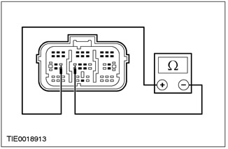
3Measure the resistance between air bag control module pin 4 C424, circuit 91S-JA14 (black/green), wiring harness side and ground. |
|
• Resistance greater than 10,000 ohms? |
|
|
→ Yes |
|
|
CHECK the air bag indicator LED/lamp. REPEAT the self-test, CLEAR the DTCs. RE-ACTIVATE the system. For additional information, refer to Supplemental Restraint System (SRS) Air Bags and Seat Belt Pretensioners (SRS) in this section. |
|
|
→ No |
|
|
REPAIR circuit 91S-JA14 (black/green). REPEAT the self-test, CLEAR the DTCs. REACTIVATE the system. For additional information, refer to Supplemental Restraint System of the Air Bags and Seat Belt Tensioners (SRS) in this section. |
|
|
AM6: CHECKING THE AIR BAG WARNING LAMP OPERATION (CONTINUED) |
|
|
1With a fused jumper wire (7.5A) installed between pin 4 C424 of the airbag control module, electrical circuit 91S-JA14 (black/green), harness side, and ground. |
|

|
2Disconnect the connecting wire with the fuse from the ground. |
|
• Is the airbag indicator light on? |
|
|
→ Yes |
|
|
INSTALL a new air bag control module. REPEAT the self-test, CLEAR the DTCs. REACTIVATE the system. For additional information, refer to Supplemental Restraint System (SRS) Air Bags and Seat Belt Pretensioners (SRS) in this section. |
|
|
→ No |
|
|
REPEAT the self-test, CLEAR the DTCs. REACTIVATE the system. For additional information, refer to Supplemental Restraint System (SRS) Air Bags and Seat Belt Tensioners (SRS) in this section. |
|
PINPOINT TEST AN: DTC B1870: AIR BAG WARNING LAMP CIRCUIT SHORT TO BATTERY POSITION
|
STATES |
DETAILS/RESULTS/ACTIONS |
|
WARNING: Wait at least one minute after disconnecting the battery ground cable before disconnecting any auxiliary restraint system connector. Failure to follow this instruction could result in injury. |
|
|
AN1: CHECKING THE AIR BAG WARRANTY LAMP CIRCUIT |
|
|
1Deactivate the supplemental restraint system. For more information, refer to Supplemental Restraint System of Air Bags and Seat Belt Tensioners (SRS) in this section. |
|
|
2Disconnect C424 Air Bag Control Module. |
|
|
3Disconnect C809 instrument cluster. |
|
|
4Enter the ON position. |
|
|
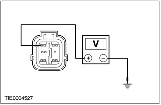
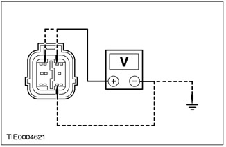
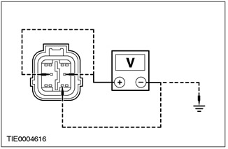
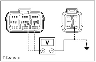
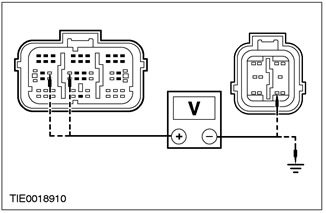
5Measure the voltage between air bag control module C424 pin 4, circuit 91S-JA14 (GN/BK), wiring harness side and ground. |
|
• Is voltage registered? |
|
|
→ Yes |
|
|
REPAIR circuit 91S-JA14 (black/green) and 15-JA10 (green/orange). REPEAT the self-test, CLEAR the DTCs. REACTIVATE the system. For additional information, refer to Supplemental Restraint System of the Air Bags and Seat Belt Pretensioners (SRS) in this section. |
|
|
→ No |
|
|
CHECK the instrument cluster. Refer to Section 413-01 for additional information. REPEAT the self-test, CLEAR the DTCs. REACTIVATE the system. Refer to Supplemental Restraint System Air Bags and Seat Belt Pretensioners (SRS) in this section for additional information. |
|
PINPOINT TEST AO: DTC B1887: DRIVER AIR BAG CIRCUIT SHORT TO GROUND
|
STATES |
DETAILS/RESULTS/ACTIONS |
|
WARNING: Wait at least one minute after disconnecting the battery ground cable before disconnecting any auxiliary restraint system connector. Failure to follow this instruction could result in injury. |
|
|
AO1: CHECK DRIVER AIR BAG ELECTRICAL CIRCUIT |
|
|
1Deactivate the supplemental restraint system. For more information, refer to Supplemental Restraint System Air Bags and Seat Belt Tensioners (SRS) in this section. |
|
|
2Enter the ON position. |
|
|
3Perform a self-test with the simulators installed. |
|
|
• Is the system functioning properly? |
|
|
→ Yes |
|
|
Go to AO2 |
|
|
→ No |
|
|
Go to AO3 |
|
|
AO2: CHECKING THE DRIVER AIR BAG MODULE |
|
|
WARNING: Do not continue this test without WDS. Failure to follow this instruction may result in injury. |
|
|
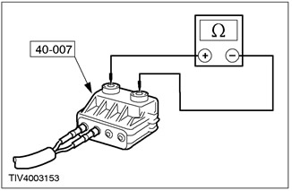
1Connect the test/deployment initiation wire 40-007-01 to the driver air bag module. |
|
|
2Select the DMM option on WDS. |
|
|
3Connect the test/trigger wire to the WDS. |
|

|
4Measure the resistance between each of the pins and the airbag module housing. |
|
• Resistance greater than 10,000 ohms? |
|
|
→ Yes |
|
|
REPEAT the self-test, CLEAR the DTCs. REACTIVATE the system. For additional information, refer to Supplemental Restraint System (SRS) Air Bags and Seat Belt Tensioners (SRS) in this section. |
|
|
→ No |
|
|
INSTALL a new driver air bag module. REPEAT the self-test, CLEAR the DTCs. REACTIVATE the system. For additional information, refer to Supplemental Restraint System (SRS) Air Bags and Seat Belt Pretensioners (SRS) in this section. |
|
|
AO3: CHECK AUXILIARY AIR BAG WIRING HARNESS FOR SHORT CIRCUIT "MASS" |
|
|
1Enter the OFF position. |
|
|
2Disconnect C424 Air Bag Control Module. |
|
|
3Disconnect the Driver Air Bag Module Simulator. |
|

|
4Measure the resistance between: - pin 2 C424 of the airbag control module, electrical circuit 15S-JA8 (green/red), and pin 9, electrical circuit 91-JA10 (black/red), on the wiring side; and - pin 2 C424 of the airbag control module, electrical circuit 15S-JA8 (green-red), on the wiring side, and "ground"; and - pin 3 C424 of the airbag control module, electrical circuit 91S-JA8 (black/orange), and pin 9, electrical circuit 91-JA10 (black/red), on the wiring side; and - pin 3 C424 of the airbag control module, electrical circuit 91S-JA8 (black-orange), on the wiring side, and ground. |
|
5Turn the steering wheel from lock to lock and note the resistance reading. |
|
|
• Is the resistance greater than 10,000 Ohms in all cases? |
|
|
→ Yes |
|
|
REPEAT the self-test, CLEAR the DTCs. REACTIVATE the system. For additional information, refer to Supplemental Restraint System (SRS) Air Bags and Seat Belt Tensioners (SRS) in this section. |
|
|
→ No |
|
|
Go to AO4 |
|
|
AO4: CHECKING THE CLOCK SPRING FOR A SHORT CIRCUIT "MASS" |
|
|
1Disconnect the Driver Air Bag Module Wiring Harness - C921. |
|

|
2Measure the resistance between: - pin 2 C424 of the airbag control module, electrical circuit 15S-JA8 (green/red), and pin 9, electrical circuit 91-JA10 (black/red), on the wiring side; and - pin 2 C424 of the airbag control module, electrical circuit 15S-JA8 (green-red), on the wiring side, and "ground"; and - pin 3 C424 of the airbag control module, electrical circuit 91S-JA8 (black/orange), and pin 9, electrical circuit 91-JA10 (black/red), on the wiring side; and - pin 3 C424 of the airbag control module, electrical circuit 91S-JA8 (black-orange), on the wiring side, and ground. |
|
3Turn the steering wheel from lock to lock and note the resistance reading. |
|
|
• Resistance greater than 10,000 ohms? |
|
|
→ Yes |
|
|
INSTALL a new air bag wiring harness. REPEAT the self-test, CLEAR the DTCs. RE-ACTIVATE the system. For additional information, refer to Supplemental Restraint System (SRS) Air Bags and Seat Belt Pretensioners (SRS) in this section. |
|
|
→ No |
|
|
Go to AO5 |
|
|
AO5: CHECK DRIVER AIR BAG MODULE CIRCUIT FOR SHORT CIRCUITS "MASS" |
|
|
1Disconnect C896 or C898 clock spring. |
|

|
2Measure the resistance between: - pin 2 C424 of the airbag control module, electrical circuit 15S-JA8 (green/red), and pin 9, electrical circuit 91-JA10 (black/red), on the wiring side; and - pin 2 C424 of the airbag control module, electrical circuit 15S-JA8 (green-red), on the wiring side, and "ground"; and - pin 3 C424 of the airbag control module, electrical circuit 91S-JA8 (black/orange), and pin 9, electrical circuit 91-JA10 (black/red), on the wiring side; and - pin 3 C424 of the airbag control module, electrical circuit 91S-JA8 (black-orange), on the wiring side, and ground. |
|
• Is the resistance greater than 10,000 Ohms in all cases? |
|
|
→ Yes |
|
|
INSTALL a new clock spring. For additional information, refer to Clock Spring in this section. REPEAT the self-test, CLEAR the DTCs. REACTIVATE the system. For additional information, refer to Supplemental Restraint System of the Air Bags and Seat Belt Pretensioners (SRS) in this section. |
|
|
→ No |
|
|
REPAIR circuit 15S-JA8 (green/red) or 91S-JA8 (black/orange) and 91-JA10 (black/red). REPEAT self-test, CLEAR DTCs. REACTIVATE the system. For additional information, refer to Supplemental Restraint System of the Air Bags and Seat Belt Pretensioners (SRS) in this section. |
|
PINPOINT TEST AP: DTC B1916: DRIVER AIR BAG CIRCUIT SHORT TO BATTERY POSITIVE
|
STATES |
DETAILS/RESULTS/ACTIONS |
|
AP1: CHECK AUXILIARY AIR BAG WIRING HARNESS FOR SHORT TO BATTERY + |
|
|
WARNING: Wait at least one minute after disconnecting the battery ground cable before disconnecting any auxiliary restraint system connector. Failure to follow this instruction could result in injury. |
|
|
1Deactivate the supplemental restraint system. For more information, refer to Supplemental Restraint System Air Bags and Seat Belt Tensioners (SRS) in this section. |
|
|
2Visually inspect the driver's auxiliary airbag wiring harness for damage. |
|
|
3Disconnect the Driver Air Bag Module Simulator. |
|
|
4Enter the ON position. |
|

|
5Measure the voltage between: - pin 2 C424 of the airbag control module, electrical circuit 15S-JA8 (green/red), and pin 9, electrical circuit 91-JA10 (black/red), on the wiring side; and - pin 2 C424 of the airbag control module, electrical circuit 15S-JA8 (green-red), on the wiring side, and "ground"; - pin 3 C424 of the airbag control module, electrical circuit 91S-JA8 (black/orange), and pin 9, electrical circuit 91-JA10 (black/red), on the wiring side; and - pin 3 C424 of the airbag control module, electrical circuit 91S-JA8 (black-orange), on the wiring side, and ground. |
|
• Is voltage registered? |
|
|
→ Yes |
|
|
Go to AP2 |
|
|
→ No |
|
|
CONNECT the driver air bag module simulator and the air bag control module. REPEAT the self-test, CLEAR the DTCs. RE-ACTIVATE the system. For additional information, refer to Supplemental Restraint System (SRS) Air Bags and Seat Belt Pretensioners (SRS) in this section. |
|
|
AP2: CHECKING THE CLOCK SPRING CIRCUIT FOR A SHORT TO BATTERY + |
|
|
1Enter the OFF position. |
|
|
2Disconnect C921 driver airbag wiring harness. |
|
|
3Enter the ON position. |
|

|
4Measure the voltage between: - pin 2 C424 of the airbag control module, electrical circuit 15S-JA8 (green/red), and pin 9, electrical circuit 91-JA10 (black/red), on the wiring side; and - pin 2 C424 of the airbag control module, electrical circuit 15S-JA8 (green-red), on the wiring side, and "ground"; and - pin 3 C424 of the airbag control module, electrical circuit 91S-JA8 (black/orange), and pin 9, electrical circuit 91-JA10 (black/red), on the wiring side; and - pin 3 C424 of the airbag control module, electrical circuit 91S-JA8 (black-orange), on the wiring side, and ground. |
|
5Turn the steering wheel from lock to lock and note the voltage reading. |
|
|
• Is voltage registered? |
|
|
→ Yes |
|
|
Go to AP3 |
|
|
→ No |
|
|
INSTALL a new air bag wiring harness. REPEAT the self-test, CLEAR the DTCs. RE-ACTIVATE the system. For additional information, refer to Supplemental Restraint System (SRS) Air Bags and Seat Belt Pretensioners (SRS) in this section. |
|
|
AP3: CHECK AIR BAG WIRING HARNESS FOR SHORT CIRCUIT "+ "BATTERY |
|
|
1Enter the OFF position. |
|
|
2Disconnect C896 or C898 clock spring. |
|
|
3Enter the ON position. |
|
|
4Measure the voltage between: - pin 2 C424 of the airbag control module, electrical circuit 15S-JA8 (green/red), and pin 9, electrical circuit 91-JA10 (black/red), on the wiring side; and - pin 2 C424 of the airbag control module, electrical circuit 15S-JA8 (green-red), on the wiring side, and "ground"; and - pin 3 C424 of the airbag control module, electrical circuit 91S-JA8 (black/orange), and pin 9, electrical circuit 91-JA10 (black/red), on the wiring side; and - pin 3 C424 of the airbag control module, electrical circuit 91S-JA8 (black-orange), on the wiring side, and ground. |
|
• Is voltage registered? |
|
|
→ Yes |
|
|
REPAIR circuit 15S-JA8 (green/red) or 91S-JA8 (black/orange) and 15-JA10 (green/orange) or 91S-JA13 (black/red). REPEAT self-test, CLEAR DTCs. REACTIVATE the system. For additional information, refer to Supplemental Restraint System of the Air Bags and Seat Belt Pretensioners (SRS) in this section. |
|
|
→ No |
|
|
INSTALL a new clock spring. For additional information, refer to Clock Spring in this section. REPEAT the self-test, CLEAR the DTCs. REACTIVATE the system. For additional information, refer to Supplemental Restraint System of the Air Bags and Seat Belt Pretensioners (SRS) in this section. |
|
PINPOINT TEST AQ: DTC B1932: DRIVER AIR BAG CIRCUIT OPEN OR HIGH RESISTANCE
|
STATES |
DETAILS/RESULTS/ACTIONS |
|
AQ1: CHECKING THE RESISTANCE OF THE DRIVER AIR BAG MODULE CIRCUIT |
|
|
WARNING: Wait at least one minute after disconnecting the battery ground cable before disconnecting any auxiliary restraint system connector. Failure to follow this instruction could result in injury. |
|
|
1Deactivate the supplemental restraint system. For more information, refer to Supplemental Restraint System Air Bags and Seat Belt Tensioners (SRS) in this section. |
|
|
2Enter the ON position. |
|
|
3Perform a self-test with the simulators installed. |
|
|
• Is the system functioning properly? |
|
|
→ Yes |
|
|
Go to AQ2 |
|
|
→ No |
|
|
Go to AQ3 |
|
|
AQ2: CHECK RESISTANCE OF DRIVER AIR BAG MODULE IGNITOR |
|
|
WARNING: Do not continue this test without WDS. Failure to follow this instruction may result in injury. |
|
|
1Connect the test/deployment initiation wire 40-007-01 to the driver air bag module. |
|
|
2Select the DMM option on WDS. |
|
|
3Connect the test/trigger wire to the WDS. |
|

|
4Measure the resistance of the air bag module igniter circuit. |
|
• Is the resistance between 2 and 3 ohms? |
|
|
→ Yes |
|
|
REPEAT the self-test, CLEAR the DTCs. REACTIVATE the system. For additional information, refer to Supplemental Restraint System (SRS) Air Bags and Seat Belt Tensioners (SRS) in this section. |
|
|
→ No |
|
|
INSTALL a new driver air bag module. REPEAT the self-test, CLEAR the DTCs. REACTIVATE the system. For additional information, refer to Supplemental Restraint System (SRS) Air Bags and Seat Belt Pretensioners (SRS) in this section. |
|
|
AQ3: CHECK DRIVER AIR BAG MODULE SUPPLEMENTAL WIRING HARNESS FOR OPEN OR HIGH RESISTANCE |
|
|
1Enter the OFF position. |
|
|
2Disconnect C921 driver airbag module wiring harness. |
|
|
3Measure the resistance between: - pin 2 C424 of the airbag control module, circuit 15S-JA8 (green/red), harness side, and pin 3 C921 of the clock spring, circuit 15S-JA8 (green/red), element side; and - pin 3 C424 of the airbag control module, electrical circuit 91S-JA8 (black/orange), on the wiring side, and pin 4 C921 of the clock spring, electrical circuit 91S-JA8 (black/orange), on the element side. |
|
4Turn the steering wheel from lock to lock and note the resistance reading. |
|
|
• Is the resistance less than 5 Ohms in all cases? |
|
|
→ Yes |
|
|
INSTALL a new driver air bag supplemental wiring harness REPEAT the self-test, CLEAR the DTCs. RE-ACTIVATE the system. For additional information, refer to Supplemental Restraint System (SRS) Air Bags and Seat Belt Pretensioners (SRS) in this section. |
|
|
→ No |
|
|
Go to AQ4 |
|
|
AQ4: CHECK CLOCK SPRING CIRCUIT FOR OPEN OR HIGH RESISTANCE |
|
|
1Disconnect C896 or C898 clock spring. |
|
|
NOTE:The vehicle shown is without directional stability support. 2Measure the resistance between: - pin 2 C424 air bag control module, circuit 15S-JA8 (green/red), harness side, and pin 9 C896 clock spring, circuit 15S-JA8 (green/red) (pin 4 C898 with yaw stability assist), harness side; and - pin 3 C424 of the air bag control module, circuit 91S-JA8 (black/orange), harness side, and pin 8 C896 of the clock spring, circuit 91S-JA8 (black/orange) (pin 3 C898 with yaw stability assist), harness side. |
|
• Is the resistance less than 5 Ohms in all cases? |
|
|
→ Yes |
|
|
Install a new clock spring. For additional information, refer to Clock Spring in this section. REPEAT the self-test, CLEAR the DTCs. REACTIVATE the system. For additional information, refer to Supplemental Restraint System of the Air Bags and Seat Belt Pretensioners (SRS) in this section. |
|
|
→ No |
|
|
REPAIR circuit 15S-JA8 (green/red) or 91S-JA8 (black/orange). REPEAT the self-test, CLEAR the DTCs. REACTIVATE the system. For additional information, refer to Supplemental Restraint System of the Air Bags and Seat Belt Pretensioners (SRS) in this section. |
|
PINPOINT TEST AR: DTC B1934: DRIVER AIR BAG CIRCUIT LOW RESISTANCE
|
STATES |
DETAILS/RESULTS/ACTIONS |
|
AR1: CHECKING THE RESISTANCE OF THE DRIVER AIR BAG MODULE CIRCUIT |
|
|
WARNING: Wait at least one minute after disconnecting the battery ground cable before disconnecting any auxiliary restraint system connector. Failure to do so could result in injury. |
|
|
1Deactivate the supplemental restraint system. For more information, refer to Supplemental Restraint System of Air Bags and Seat Belt Tensioners (SRS) in this section. |
|
|
2Enter the ON position. |
|
|
3Perform a self-test with the simulators installed. |
|
|
• Is the system functioning properly? |
|
|
→ Yes |
|
|
Go to AR2 |
|
|
→ No |
|
|
Go to AR3 |
|
|
AR2: CHECKING THE RESISTANCE OF THE DRIVER AIR BAG MODULE IGNITOR CIRCUIT |
|
|
WARNING: Do not continue this test without WDS. Failure to follow this instruction may result in injury. |
|
|
1Connect test/deployment wire 40-007-01 to the driver air bag module. |
|
|
2Select the DMM option on WDS. |
|
|
3Connect the test/trigger wire to the WDS. |
|
|
4Measure the resistance of the air bag module igniter circuit. |
|
• Is the resistance between 2 and 3 ohms? |
|
|
→ Yes |
|
|
REPEAT the self-test, CLEAR the DTCs. REACTIVATE the system. For additional information, refer to Supplemental Restraint System (SRS) Air Bags and Seat Belt Tensioners (SRS) in this section. |
|
|
→ No |
|
|
INSTALL a new driver air bag module. REPEAT the self-test, CLEAR the DTCs. REACTIVATE the system. For additional information, refer to Supplemental Restraint System (SRS) Air Bags and Seat Belt Pretensioners (SRS) in this section. |
|
|
AR3: CHECKING THE AIR BAG WIRING HARNESS FOR LOW RESISTANCE |
|
|
1Enter the OFF position. |
|
|
2Disconnect C921 airbag module wiring harness. |
|

|
3Measure the resistance between air bag control module C424 pin 2, circuit 15S-JA8 (GN/RD) and pin 3, circuit 91S-JA8 (BK/OG), harness side. |
|
4Turn the steering wheel from lock to lock and note the resistance reading. |
|
|
• Resistance greater than 10,000 ohms? |
|
|
→ Yes |
|
|
INSTALL a new air bag wiring harness. REPEAT the self-test, CLEAR the DTCs. RE-ACTIVATE the system. For additional information, refer to Supplemental Restraint System (SRS) Air Bags and Seat Belt Pretensioners (SRS) in this section. |
|
|
→ No |
|
|
Go to AR4 |
|
|
AR4: CHECKING THE CLOCK SPRING CIRCUIT FOR LOW RESISTANCE |
|
|
1Disconnect C896 or C898 clock spring. |
|
|
2Measure the resistance between air bag control module C424 pin 2, circuit 15S-JA8 (GN/RD) and pin 3, circuit 91S-JA8 (BK/OG), harness side. |
|
• Resistance greater than 10,000 ohms? |
|
|
→ Yes |
|
|
INSTALL a new clock spring. For additional information, refer to Clock Spring in this section. REPEAT the self-test, CLEAR the DTCs. REACTIVATE the system. For additional information, refer to Supplemental Restraint System of the Air Bags and Seat Belt Pretensioners (SRS) in this section. |
|
|
→ No |
|
|
REPAIR circuit 15S-JA8 (green/red) and 91S-JA8 (black/orange). REPEAT self-test, CLEAR DTCs. REACTIVATE the system. For additional information, refer to Supplemental Restraint System of the Air Bags and Seat Belt Pretensioners (SRS) in this section. |
|
PINPOINT TEST AS: DTC B1888: PASSENGER AIR BAG CIRCUIT SHORT TO GROUND
|
STATES |
DETAILS/RESULTS/ACTIONS |
|
AS1: CHECKING THE PASSENGER AIR BAG ELECTRICAL CIRCUIT |
|
|
WARNING: Wait at least one minute after disconnecting the battery ground cable before disconnecting any auxiliary restraint system connector. Failure to follow this instruction could result in injury. |
|
|
1Deactivate the supplemental restraint system. For more information, refer to Supplemental Restraint System Air Bags and Seat Belt Tensioners (SRS) in this section. |
|
|
2Enter the ON position. |
|
|
3Perform a self-test with the simulators installed. |
|
|
• Is the system functioning properly? |
|
|
→ Yes |
|
|
Go to AS2 |
|
|
→ No |
|
|
Go to AS3 |
|
|
AS2: CHECKING THE PASSENGER AIR BAG MODULE |
|
|
WARNING: Do not continue this test without WDS. Failure to follow this instruction may result in injury. |
|
|
1Connect the test/deployment initiation wire 40-007-01 to the driver air bag module. |
|
|
2Select the DMM option on WDS. |
|
|
3Connect the test/trigger wire to the WDS. |
|
|
4Measure the resistance between each of the pins and the airbag module housing. |
|
• Resistance greater than 10,000 ohms? |
|
|
→ Yes |
|
|
REPEAT the self-test, CLEAR the DTCs. REACTIVATE the system. For additional information, refer to Supplemental Restraint System (SRS) Air Bags and Seat Belt Tensioners (SRS) in this section. |
|
|
→ No |
|
|
INSTALL a new passenger air bag module. REPEAT the self-test, CLEAR the DTCs. REACTIVATE the system. For additional information, refer to Supplemental Restraint System (SRS) Air Bags and Seat Belt Tensioners (SRS) in this section. |
|
|
AS3: CHECK PASSENGER AIR BAG CIRCUIT FOR SHORT CIRCUIT "MASS" |
|
|
1Enter the OFF position. |
|
|
2Disconnect C424 Air Bag Control Module. |
|

|
3Measure the resistance between: - pin 5 C424 of the airbag control module, electrical circuit 15S-JA11 (green/white), and pin 9, electrical circuit 91-JA10 (black/red), on the wiring side; and - pin 5 C424 of the airbag control module, electrical circuit 15S-JA11 (green/white), on the wiring side, and ground; and - pin 6 C424 of the airbag control module, electrical circuit 91S-JA11 (black/white), and pin 9, electrical circuit 91-JA10 (black/red), on the wiring side; and - pin 6 C424 of the airbag control module, electrical circuit 91S-JA11 (black and white), on the wiring side, and ground. |
|
• Is the resistance greater than 10,000 Ohms in all cases? |
|
|
→ Yes |
|
|
REPEAT the self-test, CLEAR the DTCs. REACTIVATE the system. For additional information, refer to Supplemental Restraint System (SRS) Air Bags and Seat Belt Tensioners (SRS) in this section. |
|
|
→ No |
|
|
REPAIR circuit 15S-JA11 (green/white) or 91S-JA11 (black/white) and 91-JA10 (black/red). REPEAT self-test, CLEAR DTCs. REACTIVATE the system. For additional information, refer to Supplemental Restraint System Air Bags and Seat Belt Pretensioners (SRS) in this section. |
|
PINPOINT TEST AT: DTC B1925: PASSENGER AIR BAG CIRCUIT SHORT TO BATTERY POSITION
|
STATES |
DETAILS/RESULTS/ACTIONS |
|
AT1: CHECK THE PASSENGER AIRBAG ELECTRICAL CIRCUIT FOR A SHORT CIRCUIT ON THE BATTERY SIDE |
|
|
WARNING: Wait at least one minute after disconnecting the battery ground cable before disconnecting any auxiliary restraint system connector. Failure to follow this instruction could result in injury. |
|
|
1Deactivate the supplemental restraint system. For more information, refer to Supplemental Restraint System Air Bags and Seat Belt Tensioners (SRS) in this section. |
|
|
2Visually inspect the passenger airbag wiring harness for damage. |
|
|
3Disconnect the Passenger Air Bag Module Simulator. |
|
|
4Enter the ON position. |
|
|
5Measure the voltage between: - pin 5 C424 of the airbag control module, electrical circuit 15S-JA11 (green/white), and pin 9, electrical circuit 91-JA10 (black/red), on the wiring side; and - pin 5 C424 of the airbag control module, electrical circuit 15S-JA11 (green/white), on the wiring side, and ground; and - pin 6 C424 of the airbag control module, electrical circuit 91S-JA11 (black/white), and pin 9, electrical circuit 91-JA10 (black/red), on the wiring side; and - pin 6 C424 of the airbag control module, electrical circuit 91S-JA11 (black and white), on the wiring side, and ground. |
|
• Is voltage registered? |
|
|
→ Yes |
|
|
REPAIR circuit 15S-JA11 (green/white) or 91S-JA11 (black/white) and 15-JA10 (green/orange) or 91S-JA13 (black/red). REPEAT self-test, CLEAR DTCs. REACTIVATE the system. For additional information, refer to Supplemental Restraint System (SRS) in this section. |
|
|
→ No |
|
|
CONNECT the passenger air bag module simulator and the air bag control module. REPEAT the self-test, CLEAR the DTCs. RE-ACTIVATE the system. For additional information, refer to Supplemental Restraint System (SRS) Air Bags and Seat Belt Pretensioners (SRS) in this section. |
|
PINPOINT TEST AU: DTC B1933: PASSENGER AIR BAG CIRCUIT OPEN OR HIGH RESISTANCE
|
STATES |
DETAILS/RESULTS/ACTIONS |
|
AU1: CHECKING THE RESISTANCE OF THE PASSENGER AIR BAG MODULE CIRCUIT |
|
|
WARNING: Wait at least one minute after disconnecting the battery ground cable before disconnecting any auxiliary restraint system connector. Failure to follow this instruction could result in injury. |
|
|
1Deactivate the supplemental restraint system. For more information, refer to Supplemental Restraint System of Air Bags and Seat Belt Tensioners (SRS) in this section. |
|
|
2Enter the ON position. |
|
|
3Perform a self-test with the simulators installed. |
|
|
• Is the system functioning properly? |
|
|
→ Yes |
|
|
Go to AU2 |
|
|
→ No |
|
|
REPAIR circuit 15S-JA11 (green/white) or 91S-JA11 (black/white). REPEAT the self-test, CLEAR the DTCs. REACTIVATE the system. For additional information, refer to Supplemental Restraint System of the Air Bags and Seat Belt Pretensioners (SRS) in this section. |
|
|
AU2: CHECKING THE RESISTANCE OF THE PASSENGER AIR BAG MODULE IGNITOR CIRCUIT |
|
|
WARNING: Do not continue this test without WDS. Failure to follow this instruction may result in injury. |
|
|
1Connect the test/deployment initiation wire 40-007-01 to the passenger air bag module. |
|
|
2Select the DMM option on WDS. |
|
|
3Connect the test/trigger wire to the WDS. |
|

|
4Measure the resistance of the air bag module igniter circuit. |
|
• Is the resistance between 2 and 3 ohms? |
|
|
→ Yes |
|
|
REPEAT the self-test, CLEAR the DTCs. REACTIVATE the system. For additional information, refer to Supplemental Restraint System (SRS) Air Bags and Seat Belt Tensioners (SRS) in this section. |
|
|
→ No |
|
|
INSTALL a new passenger air bag module. REPEAT the self-test, CLEAR the DTCs. REACTIVATE the system. For additional information, refer to Supplemental Restraint System (SRS) Air Bags and Seat Belt Tensioners (SRS) in this section. |
|
PINPOINT TEST AV: DTC B1935: PASSENGER AIR BAG CIRCUIT LOW RESISTANCE
|
STATES |
DETAILS/RESULTS/ACTIONS |
|
AV1: CHECKING THE RESISTANCE OF THE PASSENGER AIR BAG MODULE CIRCUIT |
|
|
WARNING: Wait at least one minute after disconnecting the battery ground cable before disconnecting any auxiliary restraint system connector. Failure to follow this instruction could result in injury. |
|
|
1Deactivate the supplemental restraint system. For more information, refer to Supplemental Restraint System of Air Bags and Seat Belt Tensioners (SRS) in this section. |
|
|
2Enter the ON position. |
|
|
3Perform a self-test with the simulators installed. |
|
|
• Is the system functioning properly? |
|
|
→ Yes |
|
|
Go to AV2 |
|
|
→ No |
|
|
Go to AV3 |
|
|
AV2: CHECKING THE RESISTANCE OF THE PASSENGER AIR BAG MODULE IGNITOR CIRCUIT |
|
|
WARNING: Do not continue this test without WDS. Failure to follow this instruction may result in injury. |
|
|
1Connect the test/deployment initiation wire 40-007-01 to the passenger air bag module. |
|
|
2Select the DMM option on WDS. |
|
|
3Connect the test/trigger wire to the WDS. |
|

|
4Measure the resistance of the air bag module igniter circuit. |
|
• Is the resistance between 2 and 3 ohms? |
|
|
→ Yes |
|
|
REPEAT the self-test, CLEAR the DTCs. REACTIVATE the system. For additional information, refer to Supplemental Restraint System (SRS) Air Bags and Seat Belt Tensioners (SRS) in this section. |
|
|
→ No |
|
|
INSTALL a new passenger air bag module. REPEAT the self-test, CLEAR the DTCs. REACTIVATE the system. For additional information, refer to Supplemental Restraint System (SRS) Air Bags and Seat Belt Tensioners (SRS) in this section. |
|
|
AV3: CHECKING PASSENGER AIR BAG CIRCUIT FOR LOW RESISTANCE |
|
|
1Enter the OFF position. |
|
|
2Disconnect the Passenger Airbag Simulator. |
|
|
3Disconnect C424 Air Bag Control Module. |
|
|
4Measure the resistance between air bag control module C424 pin 5, circuit 15S-JA11 (GN/WH) and pin 6, circuit 91S-JA11 (BK/WH), harness side. |
|
• Resistance greater than 10,000 ohms? |
|
|
→ Yes |
|
|
REPEAT the self-test, CLEAR the DTCs. REACTIVATE the system. For additional information, refer to Supplemental Restraint System (SRS) Air Bags and Seat Belt Tensioners (SRS) in this section. |
|
|
→ No |
|
|
REPAIR circuit 15S-JA11 (green/white) and 91S-JA11 (black/white). REPEAT self-test, CLEAR DTCs. REACTIVATE the system. For additional information, refer to Supplemental Restraint System of the Air Bags and Seat Belt Tensioners (SRS) in this section. |
|
PINPOINT TEST AW: DTC B1876: DRIVER SEAT BELT TENSIONER CIRCUIT RESISTANCE OUT OF PERMISSIBLE RANGE
|
STATES |
DETAILS/RESULTS/ACTIONS |
|
AW1: CHECKING THE RESISTANCE OF THE DRIVER'S SEAT BELT TENSIONER CIRCUIT |
|
|
WARNING: Wait at least one minute after disconnecting the battery ground cable before disconnecting any auxiliary restraint system connector. Failure to follow this instruction could result in injury. |
|
|
1Deactivate the supplemental restraint system. For more information, refer to Supplemental Restraint System Air Bags and Seat Belt Tensioners (SRS) in this section. |
|
|
2Enter the ON position. |
|
|
3Perform a self-test with the simulators installed. |
|
|
• Is the system functioning properly? |
|
|
→ Yes |
|
|
INSTALL a new driver seat belt pretensioner. Refer to Section 501-20A / 501-20B for additional information. REPEAT the self-test, CLEAR the DTCs. REACTIVATE the system. Refer to Supplemental Restraint System (SRS) in this section for additional information. |
|
|
→ No |
|
|
CHECK the air bag module simulator for proper installation. REPEAT the self-test, CLEAR the DTCs. REACTIVATE the system. For additional information, refer to Supplemental Restraint System (SRS) Air Bags and Seat Belt Pretensioners (SRS) in this section. |
|
PINPOINT TEST AX: DTC B1877: DRIVER SEAT BELT TENSIONER CIRCUIT OPEN OR HIGH RESISTANCE
|
STATES |
DETAILS/RESULTS/ACTIONS |
|
AX1: CHECKING THE DRIVER SEAT BELT TENSIONER ELECTRICAL CIRCUIT |
|
|
WARNING: Wait at least one minute after disconnecting the battery ground cable before disconnecting any auxiliary restraint system connector. Failure to follow this instruction could result in injury. |
|
|
1Deactivate the supplemental restraint system. For more information, refer to Supplemental Restraint System Air Bags and Seat Belt Tensioners (SRS) in this section. |
|
|
2Enter the ON position. |
|
|
3Perform a self-test with the simulators installed. |
|
|
• Is the system functioning properly? |
|
|
→ Yes |
|
|
CHECK that the driver seat belt pretensioner connector is properly positioned in the block under the driver's seat. INSTALL a new driver seat belt pretensioner. Refer to Section 501-20A / 501-20B for additional information. REPEAT the self-test, CLEAR the DTCs. REACTIVATE the system. Refer to Supplemental Restraint System (SRS) in this section for additional information. |
|
|
→ No |
|
|
Go to AX2 |
|
|
AX2: CHECK DRIVER SEAT BELT TENSIONER ELECTRICAL CIRCUIT FOR OPEN OR HIGH RESISTANCE |
|
|
1Enter the OFF position. |
|
|
2Disconnect C423 Air Bag Control Module. |
|
|
3Disconnect the Airbag Simulator located under the driver's seat. |
|
|
4Measure the resistance between: - pin 11 C423 of the airbag control module, circuit 15S-JA33 (green/blue), harness side, and pin 4 C30 of the connector located under the driver's seat, circuit 15S-JA33 (green/blue), harness side; and - pin 12 C423 of the airbag control module, electrical circuit 91S-JA33 (black/blue), harness side, and pin 3 C30 of the connector located under the driver's seat, electrical circuit 91S-JA33 (black/blue), harness side. |
|
• Is the resistance less than 5 Ohms in all cases? |
|
|
→ Yes |
|
|
REPEAT the self-test, CLEAR the DTCs. RE-ACTIVATE the system. For additional information, refer to Supplemental Restraint System (SRS) Air Bags and Seat Belt Tensioners (SRS) in this section. |
|
|
→ No |
|
|
REPAIR circuit 15S-JA33 (green/blue) or 91S-JA33 (black/blue). REPEAT the self-test, CLEAR the DTCs. REACTIVATE the system. For additional information, refer to Supplemental Restraint System of the Air Bags and Seat Belt Pretensioners (SRS) in this section. |
|
PINPOINT TEST AY: DTC B1878: SEAT BELT TENSIONER CIRCUIT, DRIVER, SHORT TO BATTERY +
|
STATES |
DETAILS/RESULTS/ACTIONS |
|
AY1: CHECKING THE DRIVER SEAT BELT TENSIONER ELECTRICAL CIRCUIT |
|
|
WARNING: Wait at least one minute after disconnecting the battery ground cable before disconnecting any auxiliary restraint system connector. Failure to follow this instruction could result in injury. |
|
|
1Deactivate the supplemental restraint system. For more information, refer to Supplemental Restraint System Air Bags and Seat Belt Tensioners (SRS) in this section. |
|
|
2Enter the ON position. |
|
|
3Perform a self-test with the simulators installed. |
|
|
• Is the system functioning properly? |
|
|
→ Yes |
|
|
INSTALL a new driver seat belt pretensioner. Refer to Section 501-20A / 501-20B for additional information. REPEAT the self-test, CLEAR the DTCs. REACTIVATE the system. Refer to Supplemental Restraint System (SRS) in this section for additional information. |
|
|
→ No |
|
|
Go to AY2 |
|
|
AY2: CHECK THE DRIVER SEAT BELT TENSIONER ELECTRICAL CIRCUIT FOR A SHORT TO BATTERY + |
|
|
1Enter the OFF position. |
|
|
2Disconnect C423 and C424 of the airbag control module. |
|
|
3Disconnect the airbag simulator installed under the driver's seat. |
|
|
4Enter the ON position. |
|
|
5Measure the voltage between: - pin 11 C423 of the airbag control module, circuit 15S-JA33 (green/blue), harness side, and pin 9 C424 of the airbag control module, circuit 91-JA10 (black/red), harness side; and - pin 11 C423 of the airbag control module, electrical circuit 15S-JA33 (green-blue), on the wiring side, and ground; and - pin 12 C423 of the airbag control module, circuit 91S-JA33 (black/blue), harness side, and pin 9 C424 of the airbag control module, circuit 19-JA10 (black/red), harness side; and - pin 12 C423 of the airbag control module, electrical circuit 91S-JA33 (black and blue), on the wiring side, and ground. |
|
• Is voltage registered? |
|
|
→ Yes |
|
|
REPAIR circuit 15S-JA33 (green/blue) or 91S-JA33 (black/blue) and 15-JA10 (green/orange) or 91S-JA13 (black/red). REPEAT self-test, CLEAR DTCs. REACTIVATE the system. For additional information, refer to Supplemental Restraint System of the Air Bags and Seat Belt Pretensioners (SRS) in this section. |
|
|
→ No |
|
|
REPEAT the self-test, CLEAR the DTCs. REACTIVATE the system. For additional information, refer to Supplemental Restraint System (SRS) Air Bags and Seat Belt Tensioners (SRS) in this section. |
|
PINPOINT TEST AZ: DTC B1879: SEAT BELT TENSIONER CIRCUIT, DRIVER, SHORT TO GROUND
|
STATES |
DETAILS/RESULTS/ACTIONS |
|
AZ1: CHECKING THE DRIVER'S SEAT BELT TENSIONER ELECTRICAL CIRCUIT |
|
|
WARNING: Wait at least one minute after disconnecting the battery ground cable before disconnecting any auxiliary restraint system connector. Failure to follow this instruction could result in injury. |
|
|
1Deactivate the supplemental restraint system. For more information, refer to Supplemental Restraint System Air Bags and Seat Belt Tensioners (SRS) in this section. |
|
|
2Enter the ON position. |
|
|
3Perform a self-test with the simulators installed. |
|
|
• Is the system functioning properly? |
|
|
→ Yes |
|
|
INSTALL a new driver seat belt pretensioner. Refer to Section 501-20A / 501-20B for additional information. REPEAT the self-test, CLEAR the DTCs. REACTIVATE the system. Refer to Supplemental Restraint System (SRS) in this section for additional information. |
|
|
→ No |
|
|
Go to AZ2 |
|
|
AZ2: CHECK THE DRIVER SEAT BELT TENSIONER ELECTRICAL CIRCUIT FOR A SHORT CIRCUIT "MASS" |
|
|
1Enter the OFF position. |
|
|
2Disconnect C423 and C424 of the airbag control module. |
|
|
3Disconnect the airbag simulator installed under the driver's seat. |
|
|
4Measure the resistance between: - pin 11 C423 of the airbag control module, circuit 15S-JA33 (green/blue), harness side, and pin 9 C424 of the airbag control module, circuit 91-JA10 (black/red), harness side; and - pin 11 C423 of the airbag control module, electrical circuit 15S-JA33 (green-blue), on the wiring side, and ground; and - pin 12 C423 of the airbag control module, circuit 91S-JA33 (black/blue), harness side, and pin 9 C424 of the airbag control module, circuit 91-JA10 (black/red), harness side; and - pin 12 C423 of the airbag control module, electrical circuit 91S-JA33 (black and blue), on the wiring side, and ground. |
|
• Is the resistance greater than 10,000 Ohms in all cases? |
|
|
→ Yes |
|
|
REPEAT the self-test, CLEAR the DTCs. REACTIVATE the system. For additional information, refer to Supplemental Restraint System (SRS) Air Bags and Seat Belt Tensioners (SRS) in this section. |
|
|
→ No |
|
|
REPAIR circuit 15S-JA33 (green/blue) or 91S-JA33 (black/blue) and 91-JA10 (black/red). REPEAT self-test, CLEAR DTCs. REACTIVATE the system. For additional information, refer to Supplemental Restraint System of the Air Bags and Seat Belt Pretensioners (SRS) in this section. |
|
PINPOINT TEST BA: DTC B1885: DRIVER SEAT BELT CIRCUIT LOW RESISTANCE
|
STATES |
DETAILS/RESULTS/ACTIONS |
|
BA1: CHECKING THE DRIVER SEAT BELT TENSIONER ELECTRICAL CIRCUIT |
|
|
WARNING: Wait at least one minute after disconnecting the battery ground cable before disconnecting any auxiliary restraint system connector. Failure to follow this instruction could result in injury. |
|
|
1Deactivate the supplemental restraint system. For more information, refer to Supplemental Restraint System Air Bags and Seat Belt Tensioners (SRS) in this section. |
|
|
2Enter the ON position. |
|
|
3Perform a self-test with the simulators installed. |
|
|
• Is the system functioning properly? |
|
|
→ Yes |
|
|
INSTALL a new driver seat belt pretensioner. Refer to Section 501-20A / 501-20B for additional information. REPEAT the self-test, CLEAR the DTCs. REACTIVATE the system. Refer to Supplemental Restraint System (SRS) in this section for additional information. |
|
|
→ No |
|
|
Go to BA2 |
|
|
BA2: CHECK DRIVER SEAT BELT TENSIONER CIRCUIT FOR LOW RESISTANCE |
|
|
1Enter the OFF position. |
|
|
2Disconnect C423 Air Bag Control Module. |
|
|
3Disconnect the airbag simulator installed under the driver's seat. |
|
|
4Measure the resistance between: - pin 11 C423 of the airbag control module, electrical circuit 15S-JA33 (green-blue), and pin 12, electrical circuit 91S-JA33 (black-blue), from the wiring side. |
|
• Resistance greater than 10,000 ohms? |
|
|
→ Yes |
|
|
REPEAT the self-test, CLEAR the DTCs. REACTIVATE the system. For additional information, refer to Supplemental Restraint System (SRS) Air Bags and Seat Belt Tensioners (SRS) in this section. |
|
|
→ No |
|
|
REPAIR circuit 15S-JA33 (green/blue) and 91S-JA33 (black/blue). REPEAT self-test, CLEAR DTCs. REACTIVATE the system. For additional information, refer to Supplemental Restraint System of the Air Bags and Seat Belt Pretensioners (SRS) in this section. |
|
PINPOINT TEST BB: DTC B1992: DRIVER SIDE AIR BAG CIRCUIT SHORT TO BATTERY +
|
STATES |
DETAILS/RESULTS/ACTIONS |
|
BB1: CHECKING THE DRIVER AIR BAG ELECTRICAL CIRCUIT |
|
|
WARNING: Wait at least one minute after disconnecting the battery ground cable before disconnecting any auxiliary restraint system connector. Failure to follow this instruction could result in injury. |
|
|
1Deactivate the supplemental restraint system. For more information, refer to Supplemental Restraint System Air Bags and Seat Belt Tensioners (SRS) in this section. |
|
|
2Enter the ON position. |
|
|
3Perform a self-test with the simulators installed. |
|
|
• Is the system functioning properly? |
|
|
→ Yes |
|
|
INSTALL a new driver side air bag module. REFER to Side Air Bag Module in this section. REPEAT the self-test, CLEAR the DTCs. REACTIVATE the system. For additional information, refer to Supplemental Restraint System (SRS) in this section. |
|
|
→ No |
|
|
Go to BB2 |
|
|
BB2: CHECK THE ELECTRICAL CIRCUIT OF THE DRIVER'S SIDE AIRBAG MODULE FOR A SHORT CIRCUIT ON THE BATTERY SIDE |
|
|
1Enter the OFF position. |
|
|
2Disconnect C423 and C424 of the airbag control module. |
|
|
3Disconnect the airbag simulator installed under the driver's seat. |
|
|
4Enter the ON position. |
|
|
5Measure the voltage between: - pin 15 C423 of the airbag control module, circuit 15S-JA37 (green/black), harness side, and pin 9 C424 of the airbag control module, circuit 91-JA10 (black/red), harness side; and - pin 15 C423 of the airbag control module, electrical circuit 15S-JA37 (green-black), on the wiring side, and ground; and - pin 16 C423 of the airbag control module, circuit 91S-JA37 (black/green), harness side, and pin 9 C424 of the airbag control module, circuit 91-JA10 (black/red), harness side; and - pin 16 C423 of the airbag control module, electrical circuit 91S-JA37 (black-green), on the wiring side, and ground. |
|
• Is voltage registered? |
|
|
→ Yes |
|
|
REPAIR circuit 15S-JA37 (green/black) or 91S-JA37 (black/green) and 15-JA10 (green/orange) or 91S-JA13 (black/red). REPEAT self-test, CLEAR DTCs. REACTIVATE the system. For additional information, refer to Supplemental Restraint System of the Air Bags and Seat Belt Pretensioners (SRS) in this section. |
|
|
→ No |
|
|
REPEAT the self-test. CLEAR the DTCs. RE-ACTIVATE the system. For additional information, refer to Supplemental Restraint System (SRS) Air Bags and Seat Belt Tensioners (SRS) in this section. |
|
PINPOINT TEST BC: DTC B1993: DRIVER SIDE AIR BAG CIRCUIT SHORT TO GROUND.
|
STATES |
DETAILS/RESULTS/ACTIONS |
|
BC1: CHECKING THE DRIVER SIDE AIR BAG CIRCUIT |
|
|
WARNING: Wait at least one minute after disconnecting the battery ground cable before disconnecting any auxiliary restraint system connector. Failure to follow this instruction could result in injury. |
|
|
1Deactivate the supplemental restraint system. For more information, refer to Supplemental Restraint System Air Bags and Seat Belt Tensioners (SRS) in this section. |
|
|
2Enter the ON position. |
|
|
3Perform a self-test with the simulators installed. |
|
|
• Is the system functioning properly? |
|
|
→ Yes |
|
|
INSTALL a new driver side airbag module. For additional information, refer to Side Airbag Module in this section. REPEAT the self-test, CLEAR the DTCs. REACTIVATE the system. For additional information, refer to Supplemental Restraint System (SRS) in this section. |
|
|
→ No |
|
|
Go to BC2 |
|
|
BC2: CHECK THE ELECTRICAL CIRCUIT OF THE DRIVER'S SIDE AIRBAG MODULE FOR A SHORT CIRCUIT ON THE "MASS". |
|
|
1Enter the OFF position. |
|
|
2Disconnect C423 and C424 of the airbag control module. |
|
|
3Disconnect the airbag simulator installed under the driver's seat. |
|
|
4Measure the resistance between: - pin 15 C423 of the airbag control module, circuit 15S-JA37 (green/black), harness side, and pin 9 C424 of the airbag control module, circuit 91-JA10 (black/red), harness side; and - pin 15 C423 of the airbag control module, electrical circuit 15S-JA37 (green-black), on the wiring side, and ground; and - pin 16 C423 of the airbag control module, circuit 91S-JA37 (black/green), harness side, and pin 9 C424 of the airbag control module, circuit 91-JA10 (black/red), harness side; and - pin 16 C423 of the airbag control module, electrical circuit 91S-JA37 (black-green), on the wiring side, and ground. |
|
• Is the resistance greater than 10,000 Ohms in all cases? |
|
|
→ Yes |
|
|
REPEAT the self-test. CLEAR the DTCs. RE-ACTIVATE the system. For additional information, refer to Supplemental Restraint System (SRS) Air Bags and Seat Belt Tensioners (SRS) in this section. |
|
|
→ No |
|
|
REPAIR circuit 15S-JA37 (green/black) or 91S-JA37 (black/green) and 91-JA10 (black/red). REPEAT self-test, CLEAR DTCs. REACTIVATE the system. For additional information, refer to Supplemental Restraint System of the Air Bags and Seat Belt Pretensioners (SRS) in this section. |
|
PINPOINT TEST BD: DTC B1994: DRIVER SIDE AIR BAG CIRCUIT OPEN OR HIGH RESISTANCE
|
STATES |
DETAILS/RESULTS/ACTIONS |
|
BD1: CHECKING THE DRIVER SIDE AIR BAG ELECTRICAL CIRCUIT |
|
|
WARNING: Wait at least one minute after disconnecting the battery ground cable before disconnecting any auxiliary restraint system connector. Failure to follow this instruction could result in injury. |
|
|
1Deactivate the supplemental restraint system. For more information, refer to Supplemental Restraint System Air Bags and Seat Belt Tensioners (SRS) in this section. |
|
|
2Enter the ON position. |
|
|
3Perform a self-test with the simulators installed. |
|
|
• Is the system functioning properly? |
|
|
→ Yes |
|
|
CHECK that the connector located under the driver's seat is properly positioned in the under-driver seat block. INSTALL a new driver's side air bag module. For additional information, refer to Side Air Bag Module in this section. REPEAT the self-test, CLEAR the DTCs. REACTIVATE the system. For additional information, refer to Supplemental Restraint System (SRS) and Seat Belt Pretensioners (SRS) in this section. |
|
|
→ No |
|
|
Go to BD2 |
|
|
BD2: CHECK DRIVER SIDE AIR BAG CIRCUIT FOR OPEN OR HIGH RESISTANCE |
|
|
1Disconnect C423 Air Bag Control Module. |
|
|
2Disconnect the airbag simulator installed under the driver's seat. |
|

|
3Measure the resistance between: - pin 15 C423 of the airbag control module, circuit 15S-JA37 (green/black), harness side, and pin 1 C30 of the connector located under the driver's seat, circuit 15S-JA37 (green/black), harness side; and - pin 16 C423 of the airbag control module, circuit 91S-JA37 (black/green), harness side, and pin 2 C30 of the connector located under the driver's seat, circuit 91S-JA37 (black/green), harness side. |
|
• Is the resistance less than 5 Ohms in all cases? |
|
|
→ Yes |
|
|
REPEAT the self-test, CLEAR the DTCs. REACTIVATE the system. For additional information, refer to Supplemental Restraint System (SRS) Air Bags and Seat Belt Tensioners (SRS) in this section. |
|
|
→ No |
|
|
REPAIR circuit 15S-JA37 (Green/Black) or 91S-JA37 (Black/Green). REPEAT the self-test, CLEAR the DTCs. REACTIVATE the system. For additional information, refer to Supplemental Restraint System of the Air Bags and Seat Belt Pretensioners (SRS) in this section. |
|
PINPOINT TEST BE: DTC B1995: DRIVER SIDE AIR BAG CIRCUIT LOW RESISTANCE
|
STATES |
DETAILS/RESULTS/ACTIONS |
|
BE1: CHECKING THE DRIVER SIDE AIR BAG ELECTRICAL CIRCUIT |
|
|
WARNING: Wait at least one minute after disconnecting the battery ground cable before disconnecting any auxiliary restraint system connector. Failure to follow this instruction could result in injury. |
|
|
1Deactivate the supplemental restraint system. For more information, refer to Supplemental Restraint System Air Bags and Seat Belt Tensioners (SRS) in this section. |
|
|
2Enter the ON position. |
|
|
3Perform a self-test with the simulators installed. |
|
|
• Is the system functioning properly? |
|
|
→ Yes |
|
|
INSTALL a new driver side airbag module. For additional information, refer to Side Airbag Module in this section. REPEAT the self-test, CLEAR the DTCs. REACTIVATE the system. For additional information, refer to Supplemental Restraint System (SRS) in this section. |
|
|
→ No |
|
|
Go to BE2 |
|
|
BE2: CHECK DRIVER SIDE AIR BAG CIRCUIT FOR LOW RESISTANCE |
|
|
1Enter the OFF position. |
|
|
2Disconnect C423 Air Bag Control Module. |
|
|
3Disconnect the Airbag Simulator installed under the passenger seat. |
|
|
4Measure the resistance between: - pin 15 C423 of the airbag control module, electrical circuit 15S-JA37 (green-black), and pin 16, electrical circuit 91S-JA37 (black-green), on the wiring side. |
|
• Resistance greater than 10,000 ohms? |
|
|
→ Yes |
|
|
REPEAT the self-test, CLEAR the DTCs. REACTIVATE the system. For additional information, refer to Supplemental Restraint System (SRS) Air Bags and Seat Belt Tensioners (SRS) in this section. |
|
|
→ No |
|
|
REPAIR circuits 15S-JA37 (green/black) and 91S-JA37 (black/green). REPEAT the self-test, CLEAR the DTCs. REACTIVATE the system. For additional information, refer to Supplemental Restraint System of the Air Bags and Seat Belt Pretensioners (SRS) in this section. |
|
PINPOINT TEST BF: DTC B2117: DRIVER SIDE AIR BAG MODULE CIRCUIT RESISTANCE OUT OF PERMISSIBLE RANGE
|
STATES |
DETAILS/RESULTS/ACTIONS |
|
BF1: CHECKING THE RESISTANCE OF THE DRIVER SIDE AIR BAG MODULE CIRCUIT |
|
|
WARNING: Wait at least one minute after disconnecting the battery ground cable before disconnecting any auxiliary restraint system connector. Failure to follow this instruction could result in injury. |
|
|
1Deactivate the supplemental restraint system. For more information, refer to Supplemental Restraint System Air Bags and Seat Belt Tensioners (SRS) in this section. |
|
|
2Enter the ON position. |
|
|
3Perform a self-test with the simulators installed. |
|
|
• Is the system functioning properly? |
|
|
→ Yes |
|
|
INSTALL a new driver side airbag module. For additional information, refer to Side Airbag Module in this section. REPEAT the self-test, CLEAR the DTCs. REACTIVATE the system. For additional information, refer to Supplemental Restraint System (SRS) in this section. |
|
|
→ No |
|
|
CHECK the airbag simulator for proper installation. REPEAT the self-test, CLEAR the DTCs. REACTIVATE the system. For additional information, refer to Supplemental Restraint System (SRS) Airbags and Seat Belt Pretensioners (SRS) in this section. |
|
PINPOINT TEST BG: DTC B2444: DRIVER SIDE IMPACT SENSOR CIRCUIT SHORT TO GROUND/IGNITION/+BATTERY CIRCUIT OR INTERNAL MALFUNCTION
|
STATES |
DETAILS/RESULTS/ACTIONS |
|
BG1: CHECKING THE DRIVER SIDE IMPACT SENSOR CIRCUIT |
|
|
WARNING: Wait at least one minute after disconnecting the battery ground cable before disconnecting any auxiliary restraint system connector. Failure to follow this instruction could result in injury. |
|
|
1Deactivate the supplemental restraint system. For more information, refer to Supplemental Restraint System Air Bags and Seat Belt Tensioners (SRS) in this section. |
|
|
2Disconnect C427 or C428 side impact sensor. |
|
|
3Disconnect the airbag control module C423. |
|
|
4Measure the resistance between: NOTE:left-hand drive variant - pin 18 C423 of the airbag control module, circuit 15S-JA39 (green/yellow), harness side, and pin 1 C427 of the driver-side impact sensor, circuit 15S-JA39 (green/yellow), harness side; and - pin 19 C423 of the airbag control module, circuit 91-JA39 (black/yellow), harness side, and pin 2 C427 of the driver-side impact sensor, circuit 91-JA39 (black/yellow), harness side. NOTE:right hand drive variant - pin 18 C423 of the airbag control module, circuit 15S-JA39 (green/yellow), harness side, and pin 1 C428 of the driver-side impact sensor, circuit 15S-JA39 (green/yellow), harness side; and - pin 19 C423 of the airbag control module, circuit 91-JA39 (black/yellow), harness side, and pin 2 C428 of the driver-side impact sensor, circuit 91-JA39 (black/yellow), harness side. |
|
• Is the resistance less than 5 Ohms in all cases? |
|
|
→ Yes |
|
|
Go to BG2 |
|
|
→ No |
|
|
REPAIR circuits 15S-JA39 (GY) and 91-JA39 (BKY). REPEAT the self-test, CLEAR the DTCs. REACTIVATE the system. For additional information, refer to Supplemental Restraint System Air Bags and Seat Belt Tensioners (SRS) in this section. |
|
|
BG2: CHECK DRIVER SIDE IMPACT SENSOR CIRCUIT FOR SHORT CIRCUIT |
|
|
1Disconnect C424 Air Bag Control Module. |
|
|
2Measure the resistance between: - pin 18 C423 of the airbag control module, circuit 15S-JA39 (green/yellow), harness side, and pin 8 C424 of the airbag control module, circuit 15-JA10 (green/orange), harness side; and - pin 18 C423 of the airbag control module, circuit 15S-JA39 (green/yellow), harness side, and pin 9 C424 of the airbag control module, circuit 91-JA10 (black/red), harness side; and - pin 18 C423 of the airbag control module, electrical circuit 15S-JA39 (green-yellow), on the wiring side, and ground; and - pin 19 C423 airbag control module, circuit 91-JA39 (black/yellow), harness side and pin 8 C424 airbag control module, circuit 15-JA10 (green/orange), harness side; and - pin 19 C423 of the airbag control module, circuit 91-JA39 (black/yellow), harness side, and pin 9 C424 of the airbag control module, circuit 91-JA10 (black/red), harness side; and - pin 19 C423 of the airbag control module, electrical circuit 91-JA39 (black-yellow), on the wiring side, and ground. |
|
• Is the resistance greater than 10,000 Ohms in all cases? |
|
|
→ Yes |
|
|
INSTALL a new side impact sensor. For additional information, refer to Side Impact Sensor in this section. REPEAT the self-test, CLEAR the DTCs. REACTIVATE the system. For additional information, refer to Supplemental Restraint System (SRS) Air Bags and Seat Belt Pretensioners in this section. |
|
|
→ No |
|
|
REPAIR circuits 15-JA10 (green/orange) or 91-JA10 (black/red) and 15S-JA39 (green/yellow) or 91-JA39 (black/yellow). REPEAT the self-test, CLEAR the DTCs. REACTIVATE the system. For additional information, refer to Supplemental Restraint System (SRS) in this section. |
|
PINPOINT TEST BH: DTC B1880: PASSENGER SEAT BELT TENSIONER CIRCUIT RESISTANCE OUT OF PERMISSIBLE RANGE
|
STATES |
DETAILS/RESULTS/ACTIONS |
|
BH1: CHECKING THE RESISTANCE OF THE PASSENGER SEAT BELT TENSIONER CIRCUIT |
|
|
WARNING: Wait at least one minute after disconnecting the battery ground cable before disconnecting any auxiliary restraint system connector. Failure to follow this instruction could result in injury. |
|
|
1Deactivate the supplemental restraint system. For more information, refer to Supplemental Restraint System Air Bags and Seat Belt Tensioners (SRS) in this section. |
|
|
2Enter the ON position. |
|
|
3Perform a self-test with the simulators installed. |
|
|
• Is the system functioning properly? |
|
|
→ Yes |
|
|
INSTALL a new passenger seat belt pretensioner. Refer to Section 501-20A / 501-20B for additional information. REPEAT the self-test, CLEAR the DTCs. REACTIVATE the system. Refer to Supplemental Restraint System (SRS) in this section for additional information. |
|
|
→ No |
|
|
CHECK the airbag simulator for proper installation. REPEAT the self-test, CLEAR the DTCs. REACTIVATE the system. For additional information, refer to Supplemental Restraint System (SRS) Airbags and Seat Belt Pretensioners (SRS) in this section. |
|
PINPOINT TEST BI: DTC 1881: PASSENGER SEAT BELT TENSIONER CIRCUIT OPEN OR HIGH RESISTANCE
|
STATES |
DETAILS/RESULTS/ACTIONS |
|
BI1: CHECKING THE PASSENGER SEAT BELT TENSIONER ELECTRICAL CIRCUIT |
|
|
WARNING: Wait at least one minute after disconnecting the battery ground cable before disconnecting any auxiliary restraint system connector. Failure to follow this instruction could result in injury. |
|
|
1Deactivate the supplemental restraint system. For more information, refer to Supplemental Restraint System Air Bags and Seat Belt Tensioners (SRS) in this section. |
|
|
2Enter the ON position. |
|
|
3Perform a self-test with the simulators installed. |
|
|
• Is the system functioning properly? |
|
|
→ Yes |
|
|
INSTALL a new passenger seat belt pretensioner. Refer to Section 501-20A / 501-20B for additional information. REPEAT the self-test, CLEAR the DTCs. REACTIVATE the system. Refer to Supplemental Restraint System (SRS) in this section for additional information. |
|
|
→ No |
|
|
Go to BI2 |
|
|
BI2: CHECK PASSENGER SEAT BELT TENSIONER ELECTRICAL CIRCUIT FOR OPEN OR HIGH RESISTANCE |
|
|
1Enter the OFF position. |
|
|
2Disconnect the airbag control module C423. |
|
|
3Disconnect the Airbag Simulator installed under the passenger seat. |
|
|
4Measure the resistance between: - pin 20 C423 of the airbag control module, electrical circuit 15S-JA34 (green/orange), harness side, and pin 4 C31 of the connector located under the driver's seat, 15S-JA34 (green/orange), harness side; and - pin 21 C423 of the airbag control module, electrical circuit 91S-JA34 (black/red), on the wiring side, and pin 3 C31 of the plug connector located under the driver's seat, 91S-JA34 (black/red), on the wiring side. |
|
• Is the resistance less than 5 Ohms in all cases? |
|
|
→ Yes |
|
|
REPEAT the self-test, CLEAR the DTCs. REACTIVATE the system. For additional information, refer to Supplemental Restraint System (SRS) Air Bags and Seat Belt Tensioners (SRS) in this section. |
|
|
→ No |
|
|
REPAIR circuits 15S-JA34 (green/orange) or 91S-JA34 (black/red). REPEAT the self-test, CLEAR the DTCs. REACTIVATE the system. For additional information, refer to Supplemental Restraint System Air Bags and Seat Belt Tensioners (SRS) in this section. |
|
PINPOINT TEST BJ: DTC B1882: PASSENGER SEAT BELT TENSIONER CIRCUIT SHORT TO BATTERY POSITION
|
STATES |
DETAILS/RESULTS/ACTIONS |
|
BJ1: CHECKING THE PASSENGER SEAT BELT TENSIONER ELECTRICAL CIRCUIT |
|
|
WARNING: Wait at least one minute after disconnecting the battery ground cable before disconnecting any auxiliary restraint system connector. Failure to follow this instruction could result in injury. |
|
|
1Deactivate the supplemental restraint system. For more information, refer to Supplemental Restraint System Air Bags and Seat Belt Tensioners (SRS) in this section. |
|
|
2Enter the ON position. |
|
|
3Perform a self-test with the simulators installed. |
|
|
• Is the system functioning properly? |
|
|
→ Yes |
|
|
INSTALL a new passenger seat belt pretensioner. Refer to Section 501-20A / 501-20B for additional information. REPEAT the self-test, CLEAR the DTCs. REACTIVATE the system. Refer to Supplemental Restraint System (SRS) in this section for additional information. |
|
|
→ No |
|
|
Go to BJ2 |
|
|
BJ2: CHECK PASSENGER SEAT BELT TENSIONER ELECTRICAL CIRCUIT FOR SHORT TO BATTERY + |
|
|
1Enter the OFF position. |
|
|
2Disconnect the airbag control module C423. |
|
|
3Disconnect the Airbag Simulator installed under the passenger seat. |
|
|
4Enter the ON position. |
|
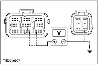
|
5Measure the voltage between: - pin 20 C423 of the airbag control module, circuit 15S-JA34 (green/orange), harness side, and pin 9 C424 of the airbag control module, circuit 91-JA10 (black/red), harness side; and - pin 20 C423 of the airbag control module, electrical circuit 15S-JA34 (green-orange), on the wiring side, and ground; and - pin 21 C423 of the airbag control module, circuit 91S-JA34 (black/red), harness side, and pin 9 C424 of the airbag control module, circuit 91-JA10 (black/red), harness side; and - pin 21 C423 of the airbag control module, electrical circuit 91S-JA34 (black/red), on the wiring side, and ground |
|
• Is there any voltage present? |
|
|
→ Yes |
|
|
REPAIR circuits 15-JA10 (green/orange) and 15S-JA34 (green/orange) or 91S-JA34 (black/red). REPEAT the self-test, CLEAR the DTCs. REACTIVATE the system. For additional information, refer to Supplemental Restraint System of the Air Bags and Seat Belt Pretensioners (SRS) in this section. |
|
|
→ No |
|
|
Repeat the self-test. CLEAR the DTCs. RE-ACTIVATE the system. For additional information, refer to Supplemental Restraint System (SRS) in this section. |
|
PINPOINT TEST BK: DTC B1883: PASSENGER SEAT BELT TENSIONER CIRCUIT SHORT TO GROUND
|
STATES |
DETAILS/RESULTS/ACTIONS |
|
BK1: CHECKING THE PASSENGER SEAT BELT TENSIONER ELECTRICAL CIRCUIT |
|
|
WARNING: Wait at least one minute after disconnecting the battery ground cable before disconnecting any auxiliary restraint system connector. Failure to follow this instruction could result in injury. |
|
|
1Deactivate the supplemental restraint system. For more information, refer to Supplemental Restraint System Air Bags and Seat Belt Tensioners (SRS) in this section. |
|
|
2Enter the ON position. |
|
|
3Perform a self-test with the simulators installed. |
|
|
• Is the system functioning properly? |
|
|
→ Yes |
|
|
INSTALL a new passenger seat belt pretensioner. Refer to Section 501-20A / 501-20B for additional information. REPEAT the self-test, CLEAR the DTCs. REACTIVATE the system. Refer to Supplemental Restraint System (SRS) in this section for additional information. |
|
|
→ No |
|
|
Go to BK2 |
|
|
BK2: CHECK THE PASSENGER SEAT BELT TENSIONER ELECTRICAL CIRCUIT FOR A SHORT CIRCUIT "MASS" |
|
|
1Enter the OFF position. |
|
|
2Disconnect C423 and C424 of the airbag control module. |
|
|
3Disconnect the Airbag Simulator installed under the passenger seat. |
|
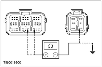
|
4Measure the resistance between: - pin 20 C423 of the airbag control module, circuit 15S-JA34 (green/orange), harness side, and pin 9 C424 of the airbag control module, circuit 91-JA10 (black/red), harness side; and - pin 20 C423 of the airbag control module, electrical circuit 15S-JA34 (green-orange), on the wiring side, and ground; and - pin 21 C423 of the airbag control module, circuit 91S-JA34 (black/red), harness side, and pin 9 C424 of the airbag control module, circuit 91-JA10 (black/red), harness side; and - pin 21 C423 of the airbag control module, electrical circuit 91S-JA34 (black/red), on the wiring side, and ground |
|
• Is the resistance greater than 10,000 Ohms in all cases? |
|
|
→ Yes |
|
|
REPEAT the self-test, CLEAR the DTCs. REACTIVATE the system. For additional information, refer to Supplemental Restraint System (SRS) Air Bags and Seat Belt Tensioners (SRS) in this section. |
|
|
→ No |
|
|
REPAIR circuits 15S-JA34 (green/orange) or 91S-JA34 (black/red) and 91-JA10 (black/red). REPEAT the self-test, CLEAR the DTCs. REACTIVATE the system. For additional information, refer to Supplemental Restraint System of the Air Bags and Seat Belt Pretensioners (SRS) in this section. |
|
PINPOINT TEST BL: DTC B1886: PASSENGER SEAT BELT TENSIONER CIRCUIT LOW RESISTANCE
|
STATES |
DETAILS/RESULTS/ACTIONS |
|
BL1: CHECKING THE PASSENGER SEAT BELT TENSIONER ELECTRICAL CIRCUIT |
|
|
WARNING: Wait at least one minute after disconnecting the battery ground cable before disconnecting any auxiliary restraint system connector. Failure to follow this instruction could result in injury. |
|
|
1Deactivate the supplemental restraint system. For more information, refer to Supplemental Restraint System Air Bags and Seat Belt Tensioners (SRS) in this section. |
|
|
2Enter the ON position. |
|
|
3Perform a self-test with the simulators installed. |
|
|
• Is the system functioning properly? |
|
|
→ Yes |
|
|
INSTALL a new passenger seat belt pretensioner. Refer to Section 501-20A / 501-20B for additional information. REPEAT the self-test, CLEAR the DTCs. REACTIVATE the system. Refer to Supplemental Restraint System (SRS) in this section for additional information. |
|
|
→ No |
|
|
Go to BL2 |
|
|
BL2: CHECK PASSENGER SEAT BELT TENSIONER CIRCUIT FOR LOW RESISTANCE |
|
|
1Enter the OFF position. |
|
|
2Disconnect the airbag control module C423. |
|
|
3Disconnect the Airbag Simulator installed under the passenger seat. |
|
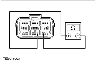
|
4Measure the resistance between: - pin 20 C423 of the airbag control module, electrical circuit 15S-JA34 (green-orange), and pin 21, electrical circuit 91S-JA34 (black-red), on the wiring side. |
|
• Resistance greater than 10,000 ohms? |
|
|
→ Yes |
|
|
REPEAT the self-test, CLEAR the DTCs. REACTIVATE the system. For additional information, refer to Supplemental Restraint System (SRS) Air Bags and Seat Belt Tensioners (SRS) in this section. |
|
|
→ No |
|
|
REPAIR circuit 15S-JA34 (green/orange) and 91S-JA34 (black/red). REPEAT self-test, CLEAR DTCs. REACTIVATE the system. For additional information, refer to Supplemental Restraint System of the Air Bags and Seat Belt Pretensioners (SRS) in this section. |
|
PINPOINT TEST BM: DTC 1996: PASSENGER SIDE AIR BAG CIRCUIT SHORT TO BATTERY +.
|
STATES |
DETAILS/RESULTS/ACTIONS |
|
BM1: CHECKING THE PASSENGER AIR BAG ELECTRICAL CIRCUIT |
|
|
WARNING: Wait at least one minute after disconnecting the battery ground cable before disconnecting any auxiliary restraint system connector. Failure to follow this instruction could result in injury. |
|
|
1Deactivate the supplemental restraint system. For more information, refer to Supplemental Restraint System Air Bags and Seat Belt Tensioners (SRS) in this section. |
|
|
2Enter the ON position. |
|
|
3Perform a self-test with the simulators installed. |
|
|
• Is the system functioning properly? |
|
|
→ Yes |
|
|
INSTALL a new passenger side air bag module. For additional information, refer to Side Air Bag Module in this section. REPEAT the self-test. CLEAR the DTCs. REACTIVATE the system. For additional information, refer to Supplemental Restraint System (SRS) in this section. |
|
|
→ No |
|
|
Go to BM2 |
|
|
BM2: CHECK THE ELECTRICAL CIRCUIT OF THE PASSENGER SIDE AIRBAG FOR A SHORT CIRCUIT ON THE BATTERY SIDE |
|
|
1Enter the OFF position. |
|
|
2Disconnect C423 and C424 of the airbag control module. |
|
|
3Disconnect the Airbag Simulator installed under the passenger seat. |
|
|
4Enter the ON position. |
|
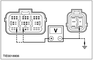
|
5Measure the voltage between: - pin 23 C423 of the airbag control module, circuit 15S-JA15 (green/red), harness side, and pin 9 C424 of the airbag control module, circuit 91-JA10 (black/red), harness side; and - pin 23 C423 of the airbag control module, electrical circuit 15S-JA15 (green-red), on the wiring side, and ground; and - pin 24 C423 of the airbag control module, circuit 91S-JA15 (black/orange), harness side, and pin 9 C424 of the airbag control module, circuit 91-JA10 (black/red), harness side; and - pin 24 C423 of the airbag control module, electrical circuit 91S-JA15 (black-orange), on the wiring side, and ground. |
|
• Is there any voltage present? |
|
|
→ Yes |
|
|
REPAIR circuits 15-JA10 (green/orange) and 15S-JA15 (green/red) or 91S-JA15 (black/orange). REPEAT the self-test, CLEAR the DTCs. REACTIVATE the system. For additional information, refer to Supplemental Restraint System of the Air Bags and Seat Belt Pretensioners (SRS) in this section. |
|
|
→ No |
|
|
REPEAT the self-test, CLEAR the DTCs. REACTIVATE the system. For additional information, refer to Supplemental Restraint System (SRS) Air Bags and Seat Belt Tensioners (SRS) in this section. |
|
PINPOINT TEST BN: DTC B1997: PASSENGER SIDE AIR BAG CIRCUIT SHORT TO GROUND
|
STATES |
DETAILS/RESULTS/ACTIONS |
|
BN1: CHECKING THE PASSENGER SIDE AIR BAG ELECTRICAL CIRCUIT |
|
|
WARNING: Wait at least one minute after disconnecting the battery ground cable before disconnecting any auxiliary restraint system connector. Failure to follow this instruction could result in injury. |
|
|
1Deactivate the supplemental restraint system. For more information, refer to Supplemental Restraint System Air Bags and Seat Belt Tensioners (SRS) in this section. |
|
|
2Enter the ON position. |
|
|
3Perform a self-test with the simulators installed. |
|
|
• Is the system functioning properly? |
|
|
→ Yes |
|
|
INSTALL a new passenger side air bag module. For additional information, refer to Side Air Bag Module in this section. REPEAT the self-test, CLEAR the DTCs. REACTIVATE the system. For additional information, refer to Supplemental Restraint System (SRS) in this section. |
|
|
→ No |
|
|
Go to BN₂ |
|
|
BN₂: CHECK PASSENGER SIDE AIR BAG CIRCUIT FOR SHORT CIRCUIT "MASS" |
|
|
1Enter the ON position. |
|
|
2Disconnect C423 and C424 of the airbag control module. |
|
|
3Disconnect the Airbag Simulator installed under the passenger seat. |
|

|
4Measure the resistance between: - pin 23 C423 of the airbag control module, circuit 15S-JA15 (green/red), harness side, and pin 9 C424 of the airbag control module, circuit 91-JA10 (black/red), harness side; and - pin 23 C423 of the airbag control module, electrical circuit 15S-JA15 (green-red), on the wiring side, and ground; and - pin 24 C423 of the airbag control module, circuit 91S-JA15 (black/orange), harness side, and pin 9 C424 of the airbag control module, circuit 91-JA10 (black/red), harness side; and - pin 24 C423 of the airbag control module, electrical circuit 91S-JA15 (black-orange), on the wiring side, and ground. |
|
• Is the resistance greater than 10,000 Ohms in all cases? |
|
|
→ Yes |
|
|
REPEAT the self-test. CLEAR the DTCs. RE-ACTIVATE the system. For additional information, refer to Supplemental Restraint System (SRS) Air Bags and Seat Belt Tensioners (SRS) in this section. |
|
|
→ No |
|
|
REPAIR circuits 15S-JA15 (green/red) or 91S-JA15 (black/orange) and 91-JA10 (black/red). REPEAT the self-test, CLEAR the DTCs. REACTIVATE the system. For additional information, refer to Supplemental Restraint System of the Air Bags and Seat Belt Pretensioners (SRS) in this section. |
|
PINPOINT TEST BO: DTC B1998: PASSENGER SIDE AIR BAG CIRCUIT OPEN OR HIGH RESISTANCE
|
STATES |
DETAILS/RESULTS/ACTIONS |
|
BO1: CHECK PASSENGER SIDE AIR BAG ELECTRICAL CIRCUIT |
|
|
WARNING: Wait at least one minute after disconnecting the battery ground cable before disconnecting any auxiliary restraint system connector. Failure to follow this instruction could result in injury. |
|
|
1Deactivate the supplemental restraint system. For more information, refer to Supplemental Restraint System of Air Bags and Seat Belt Tensioners (SRS) in this section. |
|
|
2Enter the ON position. |
|
|
3Perform a self-test with the simulators installed. |
|
|
• Is the system functioning properly? |
|
|
→ Yes |
|
|
INSTALL a new passenger side air bag module. For additional information, refer to Side Air Bag Module in this section. REPEAT the self-test, CLEAR the DTCs. REACTIVATE the system. For additional information, refer to Supplemental Restraint System (SRS) in this section. |
|
|
→ No |
|
|
Go to BO2 |
|
|
BO2: CHECK PASSENGER SIDE AIR BAG CIRCUIT FOR OPEN OR HIGH RESISTANCE |
|
|
1Disconnect the airbag control module C423. |
|
|
2Disconnect the Airbag Simulator installed under the passenger seat. |
|
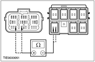
|
3Measure the resistance between: - pin 23 C423 of the airbag control module, electrical circuit 15S-JA15 (green/red), harness side, and pin 1 C31 of the connector located under the driver's seat, 15S-JA15 (green/red), harness side; and - pin 24 C423 of the airbag control module, electrical circuit 91S-JA15 (black/orange), on the wiring side, and pin 2 C31 of the connector located under the driver's seat, 91S-JA15 (black/orange), on the wiring side. |
|
• Is the resistance less than 5 Ohms in all cases? |
|
|
→ Yes |
|
|
REPEAT the self-test, CLEAR the DTCs. RE-ACTIVATE the system. For additional information, refer to Supplemental Restraint System (SRS) Air Bags and Seat Belt Tensioners (SRS) in this section. |
|
|
→ No |
|
|
REPAIR circuits 15S-JA15 (green/red) or 91S-JA15 (black/orange). REPEAT the self-test, CLEAR the DTCs. REACTIVATE the system. For additional information, refer to Supplemental Restraint System of the Air Bags and Seat Belt Pretensioners (SRS) in this section. |
|
PINPOINT TEST BP: DTC B1999: PASSENGER SIDE AIR BAG CIRCUIT LOW RESISTANCE
|
STATES |
DETAILS/RESULTS/ACTIONS |
|
BP1: CHECK PASSENGER SIDE AIR BAG ELECTRICAL CIRCUIT |
|
|
WARNING: Wait at least one minute after disconnecting the battery ground cable before disconnecting any auxiliary restraint system connector. Failure to follow this instruction could result in injury. |
|
|
1Deactivate the supplemental restraint system. For more information, refer to Supplemental Restraint System of Air Bags and Seat Belt Tensioners (SRS) in this section. |
|
|
2Enter the ON position. |
|
|
3Perform a self-test with the simulators installed. |
|
|
• Is the system functioning properly? |
|
|
→ Yes |
|
|
INSTALL a new passenger side air bag module. For additional information, refer to Side Air Bag Module in this section. REPEAT the self-test, CLEAR the DTCs. REACTIVATE the system. For additional information, refer to Supplemental Restraint System (SRS) in this section. |
|
|
→ No |
|
|
Go to BP2 |
|
|
BP2: CHECK PASSENGER SIDE AIR BAG CIRCUIT FOR LOW RESISTANCE |
|
|
1Enter the OFF position. |
|
|
2Disconnect the airbag control module C423. |
|
|
3Disconnect the Airbag Simulator installed under the passenger seat. |
|
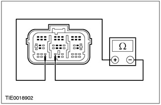
|
4Measure the resistance between pin 23, circuit 15S-JA15 (GN/RD) and pin 24, circuit 91S-JA15 (BK/OG), C423 air bag control module, harness side. |
|
• Resistance greater than 10,000 Ohms? |
|
|
→ Yes |
|
|
REPEAT the self-test, CLEAR the DTCs. RE-ACTIVATE the system. For additional information, refer to Supplemental Restraint System (SRS) Air Bags and Seat Belt Tensioners (SRS) in this section. |
|
|
→ No |
|
|
REPAIR circuits 15S-JA15 (green/red) and 91S-JA15 (black/orange). REPEAT the self-test, CLEAR the DTCs. REACTIVATE the system. For additional information, refer to Supplemental Restraint System of the Air Bags and Seat Belt Pretensioners (SRS) in this section. |
|
PINPOINT TEST BQ: DTC B2118: PASSENGER SIDE AIR BAG MODULE CIRCUIT RESISTANCE OUT OF PERMISSIBLE RANGE
|
STATES |
DETAILS/RESULTS/ACTIONS |
|
BQ1: CHECKING THE RESISTANCE OF THE PASSENGER SIDE AIR BAG MODULE CIRCUIT |
|
|
WARNING: Wait at least one minute after disconnecting the battery ground cable before disconnecting any auxiliary restraint system connector. Failure to follow this instruction could result in injury. |
|
|
1Deactivate the supplemental restraint system. For more information, refer to Supplemental Restraint System of Air Bags and Seat Belt Tensioners (SRS) in this section. |
|
|
2Enter the ON position. |
|
|
3Perform a self-test with the simulators installed. |
|
|
• Is the system functioning properly? |
|
|
→ Yes |
|
|
INSTALL a new passenger side air bag module. For additional information, refer to Side Air Bag Module in this section. REPEAT the self-test, CLEAR the DTCs. REACTIVATE the system. For additional information, refer to Supplemental Restraint System (SRS) in this section. |
|
|
→ No |
|
|
CHECK the airbag simulator for proper installation. REPEAT the self-test, CLEAR the DTCs. REACTIVATE the system. For additional information, refer to Supplemental Restraint System (SRS) Airbags and Seat Belt Pretensioners (SRS) in this section. |
|
PINPOINT TEST BR: DTC B2445: PASSENGER SIDE IMPACT SENSOR CIRCUIT SHORT TO GROUND/IGNITION CIRCUIT/+BATTERY OR INTERNAL MALFUNCTION
|
STATES |
DETAILS/RESULTS/ACTIONS |
|
BR1: CHECKING THE PASSENGER SIDE IMPACT SENSOR CIRCUIT |
|
|
WARNING: Wait at least one minute after disconnecting the battery ground cable before disconnecting any auxiliary restraint system connector. Failure to follow this instruction could result in injury. |
|
|
1Deactivate the supplemental restraint system. For more information, refer to Supplemental Restraint System of Air Bags and Seat Belt Tensioners (SRS) in this section. |
|
|
2Disconnect C427 or C428 side impact sensor. |
|
|
3Disconnect the airbag control module C423. |
|
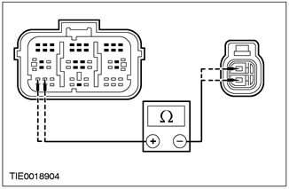
|
4Measure the resistance between: NOTE:left-hand drive variant - pin 26 C423 air bag control module, circuit 15S-JA40 (green/white), harness side and pin 1 C428 side impact sensor, circuit 15S-JA40 (green/white), harness side; and - pin 25 C423 of the airbag control module, circuit 91-JA40 (black/white), harness side, and pin 2 C428 of the side impact sensor, circuit 91-JA40 (black/white), harness side. NOTE:right hand drive variant - pin 26 C423 airbag control module, circuit 15S-JA40 (green/white), harness side, and pin 1 C427 side impact sensor, circuit 15S-JA40 (green/white), harness side; and - pin 25 C423 of the airbag control module, circuit 91-JA40 (black/white), harness side, and pin 2 C427 of the side impact sensor, circuit 91-JA40 (black/white), harness side. |
|
• Is the resistance less than 5 Ohms in all cases? |
|
|
→ Yes |
|
|
Go to BR2 |
|
|
→ No |
|
|
REPAIR circuits 15S-JA40 (green/white) or 91-JA40 (black/white). REPEAT the self-test, CLEAR the DTCs. REACTIVATE the system. For additional information, refer to Supplemental Restraint System Air Bags and Seat Belt Tensioners (SRS) in this section. |
|
|
BR2: CHECK PASSENGER SIDE IMPACT SENSOR CIRCUIT FOR SHORT CIRCUIT |
|
|
1Disconnect C424 Air Bag Control Module. |
|
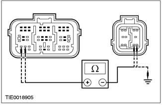
|
2Measure the resistance between: - pin 26 C423 airbag control module, circuit 15S-JA40 (green/white), harness side and pin 8 C424 airbag control module, circuit 15-JA10 (green/orange), harness side; and - pin 26 C423 of the airbag control module, circuit 15S-JA40 (green/white), harness side, and pin 9 C424 of the airbag control module, circuit 91-JA10 (black/red), harness side; and - pin 26 C423 of the airbag control module, electrical circuit 15S-JA40 (green/white), on the wiring side, and ground; and - pin 25 C423 of the airbag control module, circuit 91S-JA40 (black/white), harness side, and pin 8 C424 of the airbag control module, circuit 15-JA10 (green/orange), harness side; and - pin 25 C423 of the airbag control module, circuit 91S-JA40 (black/white), harness side, and pin 9 C424 of the airbag control module, circuit 91-JA10 (black/red), harness side; and - pin 25 C423 of the airbag control module, electrical circuit 91S-JA40 (black and white), on the wiring side, and ground. |
|
• Is the resistance greater than 10,000 Ohms in all cases? |
|
|
→ Yes |
|
|
INSTALL a new side impact sensor. REPEAT the self-test, CLEAR the DTCs. REACTIVATE the system. For additional information, refer to Supplemental Restraint System Air Bags and Seat Belt Tensioners (SRS) in this section. |
|
|
→ No |
|
|
REPAIR circuits 15-JA10 (green/orange) and 15S-JA40 (green/yellow) or 91-JA40 (black/white). REPEAT the self-test, CLEAR the DTCs. REACTIVATE the system. For additional information, refer to Supplemental Restraint System of the Air Bags and Seat Belt Pretensioners (SRS) in this section. |
|