Contents: Checking high voltage wires ↳ Checking the resistance of high… ↳ Checking the resistance of the… ↳ Removing and installing the… ↳ Checking the vacuum delay/boost valve ↳
The contactless ignition system does not require any special maintenance, except for periodic replacement of spark plugs, cleaning and checking the condition of the cover and rotor of the distributor sensor.
NOTE: Do not test spark plugs by shorting the side electrode to ground, as this will immediately damage the commutator.
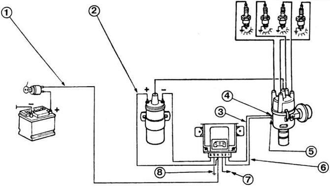 Fig. 7.49. Diagram of contactless ignition system.
1 - red wire; 2 - pink wire; 3 - green wire; 4 — pin "4"; 5 — terminal "B"; 6 - brown wire; 7 — tachometer output; 8 - green wire.
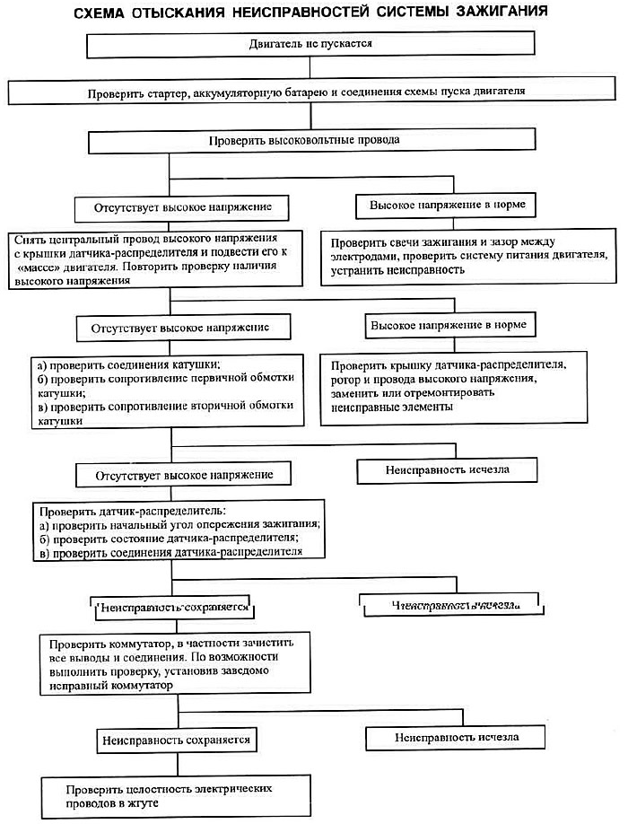
In case of malfunction or interruptions in the operation of the ignition system, check the system according to the troubleshooting diagram.
Checking high voltage wires
Pull the tip to remove the wire from the spark plug and place the tip on a spare spark plug or metal rod. Turn on the starter and check for a spark between the ground and the electrode, located at a distance of no more than 5 mm.
NOTE: It is recommended to hold the wire with pliers with insulated handles. Do not hold the electrode at a distance exceeding 5 mm from the "ground" to avoid damage to the switch.
If there is no spark, remove the central wire from the distributor cap and check it in the same way.
Checking the resistance of high voltage wires
Disconnect the wires from the battery, remove the wires from the spark plugs and ignition coil. Using an ohmmeter, measure the resistance of each wire, which should not exceed 7500 Ohms. Otherwise, replace the wire.
Checking the resistance of the ignition coil windings
Connecting an ohmmeter to the low voltage terminals, measure the resistance of the primary winding (0.72–0.88 Ohm), and between the high voltage terminals, measure the resistance of the secondary winding of the ignition coil (4.5–7.0 kOhm).
Removing and installing the distributor sensor and setting the ignition timing
Removal and installation of the distributor sensor and setting the ignition timing are performed in the order recommended for the ignition system with a distributor. The only difference is the pulse sensor connector (disconnect when removing and connect when installing the distributor sensor).
Checking the vacuum delay/boost valve
Assemble the test circuit shown in Fig. 7.50.
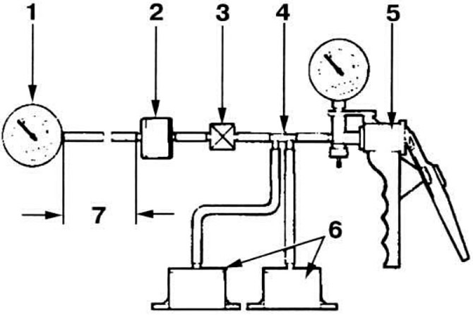 Fig. 7.50. Vacuum delay/amplification valve test diagram.
1 - device for measuring vacuum; 2 - valve being tested; 3 - crane; 4 - connecting pipe; 5 - hand vacuum pump; 6 - vacuum receivers; 7 - tube 60 cm long.
Connect the side of the delay valve marked "CARB" to a vacuum pump, and the side of the vacuum booster valve marked "DIST" to a vacuum meter. Create a vacuum of 250 mm Hg with the control valve closed. Open the valve and note the time it takes for the vacuum to reach 200 mm Hg, which should be 1-9 sec for the delay valve and 8-16 sec for the vacuum booster valve.
This article is a copy from the website [FORDBOOK.ru]