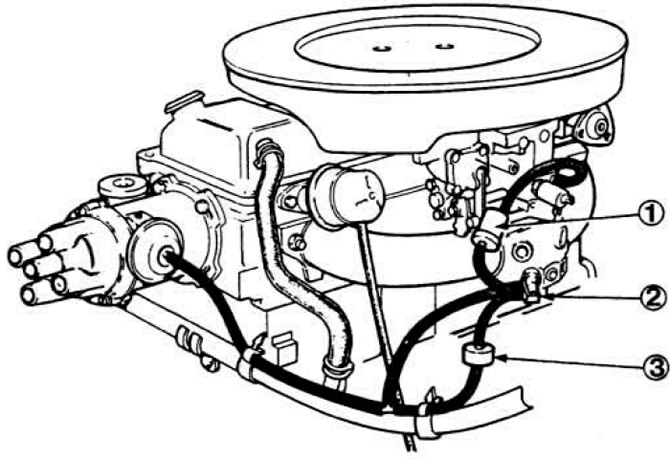
 Pic. 7.31. Vacuum ignition timing controller control device.
1 - fuel accumulator; 2 - thermostatic three-way valve; 3 - valve delay / amplification of vacuum.
The delay is carried out by a valve, the principle of which is illustrated in fig. 7.32.
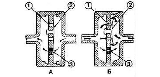 Pic. 7.32. The principle of operation of the valve delay / amplification of vacuum.
A - in the delay mode; B - in the mode of free transfer of rarefaction; 1 - opening of the return valve; 2 - return valve; 3 - nozzle.
After the engine warms up, the vacuum from the throttle space is transferred directly to the vacuum regulator. Delay time to create a vacuum of 200 mm. R. Art. from 1 to 9 sec, delay valve catalog number D 3 DE - 12 F 189 - AB, valve color - black-brown.
The operating mode of the device is determined by a three-way thermostatic valve (pic. 7.33) depending on the temperature of the coolant passing through the liquid chamber of the carburetor.
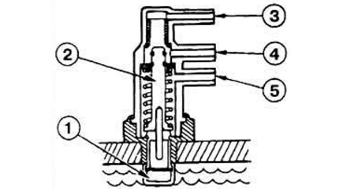 Pic. 7.33. Three-way thermostatic valve.
1 - liquid chamber; 2 - plunger; 3 - upper branch pipe; 4 - middle branch pipe; 5 - lower branch pipe.
The vacuum is transmitted to the three-way valve through the fuel accumulator 1 (pic. 7.31). which traps gasoline vapors and thereby protects the diaphragm of the vacuum regulator from their harmful effects. The middle branch pipe of the three-way valve is connected to the inlet pipeline. the upper one connects the vacuum regulator to the middle pipe (inlet pipeline) through the valve on a cold engine, the bottom pipe connects the vacuum regulator directly to the middle pipe when the coolant reaches operating temperature.
Visitor comments