Oil pump
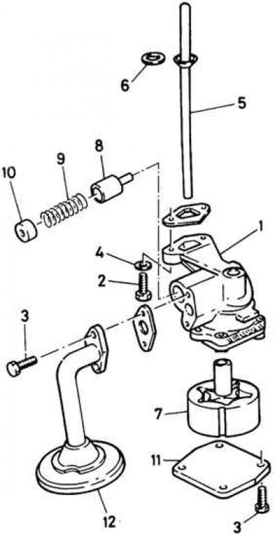
1 – housing, 2, 3 – bolts, 4 – lock washer, 5 – drive shaft, 6 – washer, 7 – rotors, 8 – plunger, 9 – spring, 10 – plug, 11 – cover, 12 – intake tube with mesh filter
1. Check the pump for wear. If one rotor needs to be replaced, both rotors should be replaced as they are a matched pair. If the rotors are fit for further use, mark the front of the outer rotor before disassembling to ensure proper reassembly.
2. Mark the relative positions of the oil pump cover and the pump body, then unscrew and remove the bolts and spring washers. Remove the cover.
3. Carefully remove the rotors from the housing.
4. Using a center punch, punch a hole in the sealing plug of the pressure reducing valve (a new plug should be installed).
5. Tighten the self-tapping screw and use an open-end wrench to remove the sealing plug.
6. Clean all parts thoroughly in gasoline or kerosene and wipe dry with a cloth. Check the gaps with a steel ruler and a set of feeler gauges. The most important gaps are: between the protrusions of the central rotor and the convex parts of the outer rotor; between the rotor and the pump body; between both rotors and the flat end cap.
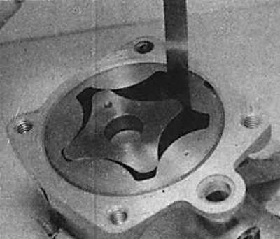
7. Check the gap between the rotor projections using a set of feeler gauges; the gap size should be within 0.05–0.20 mm.
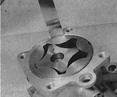
8. The gap between the outer rotor and the pump body should be within 0.15–0.30 mm.
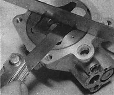
9. Place a steel ruler on the end of the pump and measure the gap between the rotors and the ruler. The gap of each rotor should be within 0.03–0.10 mm.
10. In the event that only the end gap values exceed the required values, the gaps can be reduced by removing the rotors and lapping the end surface of the housing on a lapping plate until the required gaps are achieved. It should be emphasized that the end surface of the housing must remain flat and perpendicular to the rotor axis. If the values of the other two gaps do not correspond to the values given in subsection 3.3.1, it is necessary to replace the pump with a new one.
11. Clean all parts thoroughly, reinstall the pressure relief valve and spring and lightly lubricate with engine oil.
12. Using a punch of the appropriate diameter, install a new sealing plug in place (with the flat side facing outward) flush with the surface of the flange of the inlet pipe.
13. Lubricate both rotors with engine oil and install them in the housing. Install the oil pump cover and secure it with four bolts, tighten them gradually diagonally to the required torque.
14. Install the drive shaft into the rotor drive shaft and check if the rotor turns freely.
15. Replace the inlet pipe and mesh filter.
(The text is available on the specified website info portal: «fordbook»)