|
STATES |
DETAILS/RESULTS/ACTIONS |
|
WARNING: Do not smoke or walk around with a lit cigarette or open flame of any kind while working on or near fuel related items. In such situations, there are always highly flammable mixtures that can ignite. Failure to follow these instructions may result in injury. |
|
|
WARNING: This procedure is fuel handling related. Always be aware of the possibility of fuel splashing and observe fuel handling precautions. Failure to follow these instructions may result in injury. |
|
|
CAUTION: The generator must be protected from contamination. Failure to follow this instruction may result in premature generator failure. |
|
|
A1: INSPECTION OF THE VALVE FOR LEAKAGE |
|
|
1Cover the generator with lint-free material to prevent contamination. |
|
|
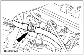
2 Inspect the valve in the fuel supply line from the fuel filter to the high pressure fuel pump for signs of diesel fuel leakage. If the valve base is wet, this indicates damage to the O-ring. |
|
• Is the valve leaking? |
|
|
→ Yes |
|
|
INSTALL a new fuel feed line from the fuel filter to the high pressure fuel pump. Check that the valve in the fuel supply line from the fuel filter to the high pressure fuel pump is in the closed position (fully screwed). Check the correct operation of the system. |
|
|
→ No |
|
|
Go to A2. |
|
|
A2: INSPECTION OF THE FUEL RETURN LINE OF THE FUEL FILTER FOR LEAKAGE |
|
|
1 Disconnect the fuel return line from the fuel filter from the high pressure fuel pump to the fuel filter. |
|
|
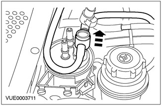
2 Inspect the fuel return line from the high pressure fuel pump to the fuel filter on the fuel filter. |
|
• Are the O-rings or the fuel return line damaged? |
|
|
→ Yes |
|
|
INSTALL a new fuel return line from the high pressure fuel pump to the fuel filter. Check the correct operation of the system. |
|
|
→ No |
|
|
Go to A3. |
|
|
A3: CHECKING AIR ENTRY POINTS |
|
|
1Cover the generator with lint-free material to prevent contamination. |
|
|
2 Using a suitable piece of clear plastic pipe, make a piping that can be installed between the high pressure fuel pump and the fuel return line from the high pressure fuel pump to the fuel filter. |
|
|
3 Install a clear plastic line between the high pressure fuel pump and the fuel return line from the high pressure fuel pump to the fuel filter. |
|
|
4 Start the engine, wait a few minutes, and then visually inspect the clear plastic piping for signs of air intrusion. |
|
|
5 Using an appropriate clean engine oil, apply one at a time to all connections, couplings and nipples of the supply and return fuel lines and after each oil application, observe the transparent plastic pipe for visible signs of air. |
|
|
• After lubricating any of the joints, couplings or nipples, does the amount of air in the transparent plastic piping decrease? |
|
|
→ Yes |
|
|
INSTALL the new fuel line in question (s). Check the correct operation of the system. |
|
|
→ No |
|
|
Go to A4. |
|
|
A4: AIR INTRODUCTION CHECK |
|
|
1Cover the generator with lint-free material to prevent contamination. |
|
|
2 Drain the fuel from the fuel tank. |
|
|
3 Fill the fuel tank with 10 liters of diesel fuel. |
|
|
4 Disconnect the fuel supply line from the fuel tank to the fuel filter from the baffle connection. |
|
|
5 Disconnect the fuel supply line from the fuel tank to the fuel filter from the fuel filter. |
|
|
6 Using a suitable piece of clear plastic tubing, fabricate and install piping between the fuel filter and the bulkhead connection between the fuel tank and the fuel filter. |
|
|
7 Remove the clear plastic line from the area between the high pressure fuel pump and the fuel return line from the high pressure fuel pump to the fuel filter. |
|

|
8 Using the special tool, prime the fuel pump until air-free fuel enters the vacuum pump reservoir. |
|
9 Remove the special tool and connect the fuel return line from the fuel pump to the fuel filter. |
|
|
10 Start the engine, wait a few minutes to purge any remaining air from the fuel system. A small amount of air is allowed to enter the fuel system, but a constant flow of air in the fuel system is not acceptable. |
|
|
11 Leave the vehicle overnight. |
|
|
• Are there any signs of air in the clear plastic piping? |
|
|
→ Yes |
|
|
INSPECT the fuel level sensor in the fuel tank and fuel tank connections for damage or leakage. INSTALL new items as needed. |
|
|
→ No |
|
|
Install a new fuel filter. See Section 310-01A for more information. |
|
PINPOINT TEST B: AIR INTRODUCTION TO FUEL LINES - VEHICLES WITH 115 HP DIESEL ENGINE
|
STATES |
DETAILS/RESULTS/ACTIONS |
|
B1: CHECK FOR AIR INTRODUCTION TO THE FUEL SYSTEM |
|
|
WARNING: Do not smoke or walk around with a lit cigarette or open flame of any kind while working on or near fuel related items. In such situations, there are always highly flammable mixtures that can ignite. Failure to follow these instructions may result in injury. |
|
|
WARNING: This procedure is fuel handling related. Always be aware of the possibility of fuel splashing and observe fuel handling precautions. Failure to follow these instructions may result in injury. |
|
|
CAUTION: The generator must be protected from contamination. Failure to follow this instruction may result in premature generator failure. |
|
|
1Cover the generator with lint-free material to prevent contamination. |
|
|
2 Using a suitable piece of clear plastic pipe, make a piping that can be installed between the high pressure fuel pump and the fuel return line from the high pressure fuel pump to the fuel filter. |
|
|
3 Install a clear plastic line between the high pressure fuel pump and the fuel return line from the high pressure fuel pump to the fuel filter. |
|
|
4 Start the engine, wait a few minutes, and then visually inspect the clear plastic piping for signs of air intrusion. |
|
|
• Are there any signs of air in the clear plastic piping? |
|
|
→ Yes |
|
|
Navigate to B2 |
|
|
→ No |
|
|
REMOVE the clear plastic line and CONNECT the fuel return line from the fuel pump to the fuel filter. For more information on diagnosing the fuel system and related controls Refer to Section 303-04A / 303-04B / 303-04C / 303-04D / 303-04E / 303-04F / 303-04G for more information. |
|
|
B2: CHECKING AIR ENTRY POINTS |
|
|
1 Using a suitable clean engine oil, apply one at a time to all connections, couplings and nipples of the supply and return fuel lines and after each oil application, observe the transparent plastic pipe for visible signs of air in it. |
|
|
• After lubricating any of the joints, couplings or nipples, does the amount of air in the transparent plastic piping decrease? |
|
|
→ Yes |
|
|
INSTALL the new fuel line in question (s). Check the correct operation of the system. |
|
|
→ No |
|
|
Install a new fuel filter. See Section 310-01A for more information. |
|
Visitor comments