|
STATES |
DETAILS/RESULTS/ACTIONS |
|
U1: CHECK FUSE F42 (CJB) |
|
|
1 Enter the OFF position. |
|
|
2CHECK Fuse F42 (CJB). |
|
|
3 Check fuse F42 (15 A). |
|
|
• Is the fuse good? |
|
|
→ Yes |
|
|
Go to U2 |
|
|
→ No |
|
|
INSTALL a new fuse F42 (15 A) and CHECK the system is working properly. If the fuse blows again, LOCATE and REPAIR the short circuit using the wiring diagrams. CHECK the system is working properly. |
|
|
U2: FUSE VOLTAGE CHECK F42 (CJB) |
|
|
1 Connect Fuse F42 (CJB). |
|
|
2 Drive the ON position. |
|
|
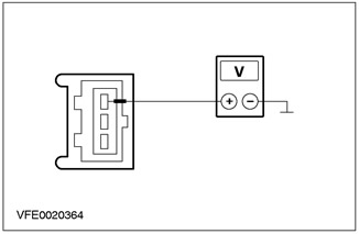
3 Measure the voltage between F42 (CJB) and "mass". |
|
|
• Does the battery voltage register? |
|
|
→ Yes |
|
|
Go to U3 |
|
|
→ No |
|
|
Using the wiring diagrams, RESTORE power to fuse F42. If necessary, INSTALL a new CJB. Check the correct operation of the system. |
|
|
U3: STOP LIGHT SWITCH VOLTAGE CHECK |
|
|
1 Enter the OFF position. |
|
|
2 Disconnect C444 brake light switch. |
|
|
3 Drive the ON position. |
|
|
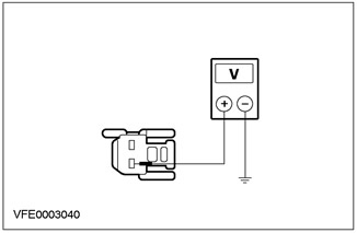
4 Measure the voltage between pin 3 of connector C444 brake light switch circuit 15-LG23 (green-white), from the wiring side, and "ground". |
|
• Does the battery voltage register? |
|
|
→ Yes |
|
|
Go to U4 |
|
|
→ No |
|
|
LOCATE and use the wiring diagrams REPAIR open circuit 15-LG23 (green-white) between fuse F42 and brake light switch. Check the correct operation of the system. |
|
|
U4: STOP LIGHT SWITCH TEST |
|
|
1 Enter the OFF position. |
|
|
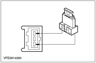
2 Install fusible jumper wire (15 A) to connector C444 of the brake light switch between pin 3, circuit 15-LG23 (green-white), and pin 1, electric circuit 15S-LG41B (green-red), from the side of the electrical wiring,. |
|
3 Drive the ON position. |
|
|
4 Check the brake lights. |
|
|
• Are the brake lights on? |
|
|
→ Yes |
|
|
INSTALL a new brake light switch. Check the correct operation of the system. |
|
|
→ No |
|
|
LOCATE and, using the wiring diagrams, REPAIR open circuit 15S-LG41B (green-red) and 15S-LG41A (green-red) between the brake light switch and splice S154. Check the correct operation of the system. |
|
PINPOINT TEST V: ONE OR MORE STOP LIGHTS DO NOT WORK
|
STATES |
DETAILS/RESULTS/ACTIONS |
|
V1: DETERMINING THE STATE IN WHICH THE FAULTY APPEARS |
|
|
1 Drive the ON position. |
|
|
2 Turn on STOP LIGHTS. |
|
|
3 Check the brake lights. |
|
|
• Upper brake light not working? |
|
|
→ Yes |
|
|
Go to V2 |
|
|
→ No |
|
|
Go to V3 |
|
|
V2: HIGH STOP LIGHT CHECK |
|
|
1 Enter the OFF position. |
|
|
2 Disconnect C107 upper brake light. |
|
|
3 Drive the ON position. |
|
|
4 Turn on STOP LIGHTS. |
|
|
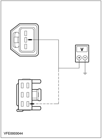
5 Measure the voltage between pin 1 of connector C107 of the upper brake light, circuit 15S-LG6 (green-yellow), from the wiring side, and "ground". |
|
• Does the battery voltage register? |
|
|
→ Yes |
|
|
LOCATE and, using the wiring diagrams, REPAIR open circuit 31-LG6 (black) between the upper brake light and earth points G35 and G15. INSTALL a new upper brake light if necessary. Check the correct operation of the system. |
|
|
→ No |
|
|
LOCATE and, using the wiring diagrams, REPAIR open circuit 15S-LG6 (green-yellow) between splice S154 and upper brake light. INSTALL a new upper brake light if necessary. Check the correct operation of the system. |
|
|
V3: IDENTIFY THE STATE IN WHICH THE FAULT IS APPEARING. |
|
|
1 Drive the ON position. |
|
|
2 Turn on STOP LIGHTS. |
|
|
3 Check the brake lights. |
|
|
• Are both brake lights not working? |
|
|
→ Yes |
|
|
Go to V4 |
|
|
→ No |
|
|
Left side: Go to V5 |
|
|
Right side: Go to V6 |
|
|
V4: LEFT REAR LIGHT ASSEMBLY ELECTRICAL CHECK |
|
|
1 Enter the OFF position. |
|
|
2 Disconnect the Left Tail Light Assembly. - C472 (3-door/5-door variant) - C474 ("station wagon") - C476 (4-door variant) |
|
|
3 Drive the ON position. |
|
|
4 Turn on STOP LIGHTS. |
|

|
5 Measure the voltage between pin 1 of connector C474 and connector C476 respectively (respectively pin 2 of connector C472) left tail light assembly, electrical circuit 15S-LG14A (green-red), from the wiring side, and "ground". |
|
• Does the battery voltage register? |
|
|
→ Yes |
|
|
LOCATE and, using the wiring diagrams, REPAIR open circuit 31-DA18 (black) between splice S184 and earth point G46. INSTALL a new tail light assembly if necessary. Check the correct operation of the system. |
|
|
→ No |
|
|
LOCATE and, using the wiring diagrams, REPAIR open circuit 15S-LG14 (green-red) between splice S154 and splice S116 (rear lights assy). INSTALL a new tail light assembly if necessary. Check the correct operation of the system. |
|
|
V5: LEFT REAR LIGHT ASSEMBLY ELECTRICAL CHECK |
|
|
1 Enter the OFF position. |
|
|
2 Disconnect the Left Tail Light Assembly. - C472 (3-door/5-door variant) - C474 ("station wagon") - C476 (4-door variant) |
|
|
3 Drive the ON position. |
|
|
4 Turn on STOP LIGHTS. |
|

|
5 Measure the voltage between pin 1 of connector C474 and connector C476 respectively (respectively pin 2 of connector C472) left tail light assembly, electrical circuit 15S-LG14A (green-red), from the wiring side, and "ground". |
|
• Does the battery voltage register? |
|
|
→ Yes |
|
|
LOCATE and, using the wiring diagrams, REPAIR open circuit 31-LF23 (black) between tail light assembly and splice S184. INSTALL a new tail light assembly if necessary. Check the correct operation of the system. |
|
|
→ No |
|
|
LOCATE and, using the wiring diagrams, REPAIR open circuit 15S-LG14A (green-red) between splice S116 and rear light assembly. INSTALL a new tail light assembly if necessary. Check the correct operation of the system. |
|
|
V6: RIGHT TAIL LIGHT ASSEMBLY ELECTRICAL CHECK |
|
|
1 Enter the OFF position. |
|
|
2 Disconnect the Right Tail Light Assembly. - C473 (3-door/5-door variant) - C475 ("station wagon") - C477 (4-door variant) |
|
|
3 Drive the ON position. |
|
|
4 Turn on STOP LIGHTS. |
|
|
5 Measure the voltage between pin 1 of connector C475 and connector C477 respectively (respectively pin 2 of connector C473) right tail light assembly, electrical circuit 15S-LG21 (green-black), from the wiring side, and "ground". |
|
• Does the battery voltage register? |
|
|
→ Yes |
|
|
LOCATE and, using the wiring diagrams, REPAIR open circuit 31-LF24 (black) between tail light assembly and splice S184. INSTALL a new tail light assembly if necessary. Check the correct operation of the system. |
|
|
→ No |
|
|
LOCATE and, using the wiring diagrams, REPAIR open circuit 15S-LG21 (green-black) between splice S116 and rear light assembly. INSTALL a new tail light assembly if necessary. Check the correct operation of the system. |
|
PINPOINT TEST W: STOP LIGHTS ON PERMANENTLY
|
STATES |
DETAILS/RESULTS/ACTIONS |
|
W1: STOP LIGHT SWITCH TEST |
|
|
1 Enter the OFF position. |
|
|
2 Disconnect the C444 brake light switch. |
|
|
3 Drive the ON position. |
|
|
4 Check the brake lights. |
|
|
• Are the brake lights on? |
|
|
→ Yes |
|
|
Go to W2 |
|
|
→ No |
|
|
INSTALL a new brake light switch. Check the correct operation of the system. |
|
|
W2: SYSTEM CHECK USING WDS |
|
|
1 Enter the OFF position. |
|
|
2 Connect C444 brake light switch. |
|
|
3 Connect the diagnostic tool. |
|
|
4 Check the system using WDS. |
|
|
• Are there any DTCs (DTC)? |
|
|
→ Yes |
|
|
PERFORM the necessary actions for the DTCs as instructed by the WDS. CLEAR fault memory and CHECK system for correct operation. |
|
|
→ No |
|
|
Go to W3 |
|
|
W3: ELIMINATE POWER SHORT CONDITION POSSIBLY CAUSED BY ABS MODULE, ESP MODULE, EEC MODULE ACCORDINGLY PROCEED |
|
|
1 Enter the OFF position. |
|
|
2 Detach one of the listed elements and then continue with the following test procedures (points 3 and 4):. -.C840 ABS module - C840 ABS/ESP module (with ESP) - C831 speed control module (with speed control) - C415 powertrain control module (common rail diesel engine only) |
|
|
3 Drive the ON position. |
|
|
4 Check the brake lights. |
|
|
• Are the brake lights on all the time? |
|
|
→ Yes |
|
|
Not all relevant components are disconnected: Switch off the ignition. Detach next item (go to point 2). |
|
|
All relevant components are disconnected: Using the wiring diagrams, LOCATE and REPAIR for a short to power in circuits connected to splices S2, S154, and S216. Check the correct operation of the system. |
|
|
→ No |
|
|
REPLACE the last detached element. Check the correct operation of the system. |
|
Visitor comments