NOTE: Use a digital multimeter to make all electrical measurements.
PINPOINT TEST O: HEADLIGHT CORRECTION DOES NOT WORK/INCORRECTLY
|
STATES |
DETAILS/RESULTS/ACTIONS |
|
O1: IDENTIFY THE STATE IN WHICH THE FAULT IS APPEARING. |
|
|
1 Drive the ON position. |
|
|
2 Turn the light switch to "DOWN LIGHT". |
|
|
3 Adjust the headlight range adjustment. |
|
|
• Are both headlights not adjustable? |
|
|
→ Yes |
|
|
Go to O6 |
|
|
→ No |
|
|
Left headlight not adjustable: Go to O2 |
|
|
Right headlight not adjustable: Go to O4 |
|
|
O2: INSPECT LEFT HEADLIGHT CORRECTION CONTROL CIRCUIT |
|
|
1 Enter the OFF position. |
|
|
2 Disconnect Headlight, left side - C835. |
|
|
3 Drive the ON position. |
|
|
4 Turn the light switch to "DOWN LIGHT". |
|
|
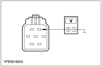
5 Measure the voltage between pin 2 of C835 left headlight circuit 64-LE45 (blue), on the wiring harness side, and "weight". |
|
• Is voltage being registered? |
|
|
→ Yes |
|
|
Go to O3 |
|
|
→ No |
|
|
REPAIR open circuit 64-LE45 (blue) between connection S106 and the left headlight using the wiring diagrams. Check the correct operation of the system. |
|
|
O3: INSPECT ELECTRICAL CIRCUITS TO HEADLIGHT ADJUSTMENT MOTOR, LEFT |
|
|
1 Enter the OFF position. |
|
|
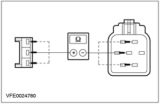
2 Measure the resistance of all circuits between the headlight beam leveling motor connector C840, harness side, and the corresponding left headlight pin, C835, component side. |
|
• Is the resistance less than 2 ohms in each case? |
|
|
→ Yes |
|
|
Check the headlight beam leveling motor for mechanical damage. If necessary, INSTALL the new element. Check the correct operation of the system. |
|
|
→ No |
|
|
REPAIR the relevant circuit using the wiring diagrams. Check the correct operation of the system. |
|
|
O4: INSPECT HEADLIGHT CORRECTION CONTROL CIRCUIT RIGHT SIDE |
|
|
1 Enter the OFF position. |
|
|
2 Disconnect Headlight, right side - C834. |
|
|
3 Drive the ON position. |
|
|
4 Turn the light switch to "DOWN LIGHT". |
|

|
5 Measure voltage between C834 right headlight pin 2, circuit 64-LE46 (blue/red), on the wiring harness side, and "weight". |
|
• Is voltage being registered? |
|
|
→ Yes |
|
|
Go to O5 |
|
|
→ No |
|
|
REPAIR open circuit 64-LE46 (blue/red) between connection S106 and the right headlight using the wiring diagrams. Check the correct operation of the system. |
|
|
O5: INSPECT ELECTRICAL CIRCUIT TO HEADLIGHT ADJUSTMENT MOTOR, RIGHT SIDE |
|
|
1 Enter the OFF position. |
|

|
2 Measure the resistance of all circuits between the headlight beam leveling motor connector C841, harness side, and the corresponding right headlight pin, C834, component side. |
|
• Is the resistance less than 2 ohms in each case? |
|
|
→ Yes |
|
|
Check the headlight beam leveling motor for mechanical damage. If necessary, INSTALL the new element. Check the correct operation of the system. |
|
|
→ No |
|
|
REPAIR the relevant circuit using the wiring diagrams. Check the correct operation of the system. |
|
|
O6: INSPECT MAIN CONTROL CIRCUIT TO HEADLIGHT CORRECTION MOTORS |
|
|
1 Enter the OFF position. |
|
|
2 Disconnect Headlight, left side - C835. |
|
|
3 Disconnect the Light Switch - C320. |
|
|
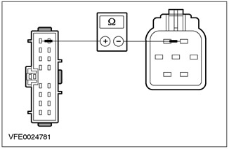
4 Measure the resistance between pin 1 C320 of the lighting switch, circuit 64-LE1 (blue/red), from the side of the wiring harness, and pin 2 C835 of the left headlight, circuit 64-LE45 (blue), from the wiring harness side. |
|
• Is the resistance less than 2 ohms? |
|
|
→ Yes |
|
|
Go to O7 |
|
|
→ No |
|
|
REPAIR open circuit 64-LE1 (blue/red) between the light switch and connection S106 using the wiring diagrams. Check the correct operation of the system. |
|
|
O7: CHECK LIGHT SWITCH GROUND |
|
|
1 Connect Headlight, left side - C835. |
|
|
2 Connect the Light Switch - C320. |
|
|
3 Drive the ON position. |
|
|
4 Turn the light switch to "FRONT FOG LIGHTS". |
|
|
5 Check the front fog light warning light built into the light switch. |
|
|
• Is the indicator lamp on? |
|
|
→ Yes |
|
|
Check the light switch If necessary, INSTALL a new element. Check the correct operation of the system. |
|
|
→ No |
|
|
REPAIR open circuit 31-LE29 (BK) between light switch and "weight" G14 using the wiring diagrams. Check the correct operation of the system. |
|
Visitor comments