|
STATES |
DETAILS/RESULTS/ACTIONS |
|
A1: CHECK F61 FUSE |
|
|
1 Enter the OFF position. |
|
|
2CHECK Fuse F61 (CJB). |
|
|
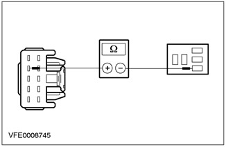
3 CHECK FUSE F61 (7.5 A) |
|
|
• Is the fuse good? |
|
|
→ Yes |
|
|
Go to A2 |
|
|
→ No |
|
|
Install new fuse F61 (7.5 A). If the fuse blows again, LOCATE and REPAIR the short circuit using the wiring diagrams. Check the correct operation of the system. |
|
|
A2: CHECK POWER SUPPLY OF F61 FUSE |
|
|
1 Connect Fuse F61 (CJB). |
|
|
2 Drive the ON position. |
|
|
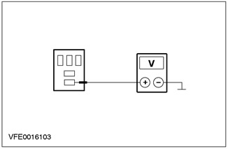
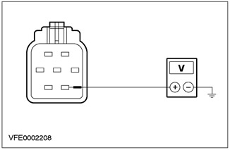
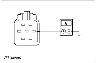
3 Measure the voltage between fuse F61 and "weight". |
|
|
• Does the battery voltage register? |
|
|
→ Yes |
|
|
Cars with daytime running lights: Go to A4 |
|
|
Vehicles without daytime running lights: Go to A3 |
|
|
→ No |
|
|
RESTORE power to fuse F61 using the wiring diagrams. Check the correct operation of the system. If the problem persists, CHECK the CJB. If necessary, INSTALL the new item. Check the correct operation of the system. |
|
|
A3: CHECK THE POWER SUPPLY OF THE LOW BEAM RELAY AND THE HIGH BEAM RELAY |
|
|
1 Enter the OFF position. |
|
|
2 Disconnect Headlight Low Relay - C1006. |
|
|
3 Drive the ON position. |
|
|
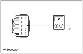
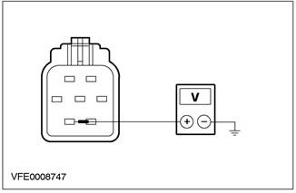
4 Measure the voltage between C1006 pin 3 of the low beam relay socket, circuit 30-LE20 (red) And "weight". |
|
• Does the battery voltage register? |
|
|
→ Yes |
|
|
Go to A4 |
|
|
→ No |
|
|
RESTORE power to the relay between the battery and the S102 connection using the wiring diagrams. Check the correct operation of the system. |
|
|
A4: CHECK GENERAL CONNECTION WITH "MASS" LOW BEAM RELAY AND HIGH BEAM RELAY |
|
|
1 Enter the OFF position. |
|

|
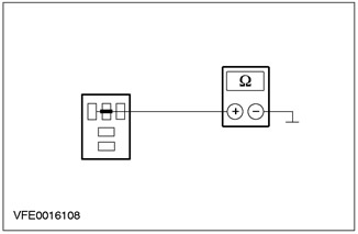
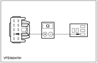
2 Measure the resistance between C1006 pin 2 of the low beam relay socket, circuit 91-LE19 (black/blue) And "weight". |
|
• Is the resistance less than 2 ohms? |
|
|
→ Yes |
|
|
Go to A5 |
|
|
→ No |
|
|
RESTORE connection with "weight" relay between connection S118 and "weight" G1 using the wiring diagrams. Check the correct operation of the system. |
|
|
A5: CHECK THE POWER SUPPLY OF THE MULTI-FUNCTION SWITCH |
|
|
1 Enter the OFF position. |
|
|
2 Disconnect the multifunction switch - C459. |
|
|
3 Drive the ON position. |
|
|
4 Turn the light switch to "DOWN LIGHT". |
|
|
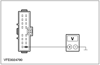
5 Measure the voltage between pin 8 C459 of the multifunction switch, circuit 15S-LE14 (green/red), from the wiring side and "weight". |
|
• Does the battery voltage register? |
|
|
→ Yes |
|
|
CHECK the multi-function switch according to the item test description attached to the wiring diagrams. If necessary, INSTALL the new element. Check the correct operation of the system. |
|
|
→ No |
|
|
Go to A6 |
|
|
A6: CHECK LIGHT SWITCH POWER SUPPLY |
|
|
1 Enter the OFF position. |
|
|
2 Disconnect the Light Switch - C320. |
|
|
3 Drive the ON position. |
|
|
4 Measure voltage between pin 8 C320 of light switch, circuit 15-LE29 (green/black), from the wiring side and "weight". |
|
• Does the battery voltage register? |
|
|
→ Yes |
|
|
Go to A7 |
|
|
→ No |
|
|
RESTORE power to the light switch between fuse F61 and light switch using the wiring diagrams. If necessary, INSTALL a new CJB. Check the correct operation of the system. |
|
|
A7: CHECK THE LIGHT SWITCH |
|
|
1 INSPECT the light switch according to the item test descriptions attached to the wiring diagrams. |
|
|
• Light switch OK? |
|
|
→ Yes |
|
|
REPAIR open circuit 15S-LE14 (green/red) between the light switch and the multifunction switch using the wiring diagrams. Check the correct operation of the system. |
|
|
→ No |
|
|
INSTALL a new light switch. Check the correct operation of the system. |
|
PINPOINT TEST B: LOW BEAM DOES NOT WORK
|
STATES |
DETAILS/RESULTS/ACTIONS |
|
B1: INSPECT LOW BEAM RELAY |
|
|
1 Enter the OFF position. |
|
|
2 Disconnect Headlight Low Relay - C1006. |
|
|
3 INSPECT the low beam relay according to the item test descriptions attached to the wiring diagrams. |
|
|
• Relay OK? |
|
|
→ Yes |
|
|
Navigate to B2 |
|
|
→ No |
|
|
INSTALL a new low beam relay. Check the correct operation of the system. |
|
|
B2: CHECK POWER SUPPLY OF LOW BEAM RELAY |
|

|
1 Measure the voltage between C1006 pin 3 of the low beam relay socket, circuit 30-LE20 (red) And "weight". |
|
• Does the battery voltage register? |
|
|
→ Yes |
|
|
Go to B3 |
|
|
→ No |
|
|
RESTORE power to the low beam relay using the wiring diagrams. Check the correct operation of the system. |
|
|
B3: CHECK BJB |
|
|
1 Enter the OFF position. |
|

|
2 Connect the jumper wire to connector C1006 of the low beam relay socket, between pin 3, circuit 30-LE20 (red), and pin 5, electric circuit 15S-LE20 (green/red). |
|
3 Drive the ON position. |
|
|
4 Check the low beam headlights. |
|
|
• Is the dipped beam on? |
|
|
→ Yes |
|
|
Go to B4 |
|
|
→ No |
|
|
Check BJB If necessary, INSTALL a new element. Check the correct operation of the system. |
|
|
B4: CHECK CONNECTION TO "MASS" HEADLIGHT RELAY |
|
|
1 Enter the OFF position. |
|
|
2 Measure the resistance between C1006 pin 2 of the low beam relay socket, circuit 91-LE19 (black/blue) And "weight". |
|
• Is the resistance less than 2 ohms? |
|
|
→ Yes |
|
|
Go to B5 |
|
|
→ No |
|
|
REPAIR the ground between the dipped beam relay and connection S118 using the wiring diagrams. Check the correct operation of the system. |
|
|
B5: INSPECT LOW BEAM RELAY CONTROL CIRCUIT |
|
|
1 Disconnect Turn Signal Switch - C459. |
|
|
2 Measure the resistance between pin 9 C459 turn signal switch circuit 15S-LE19 (green/blue), wiring side, and pin 1 C1006 of the low beam relay socket, circuit 15S-LE19 (green/blue). |
|
• Is the resistance less than 2 ohms? |
|
|
→ Yes |
|
|
CHECK the turn signal switch according to the item test description attached to the wiring diagrams. If necessary, INSTALL the new element. Check the correct operation of the system. |
|
|
→ No |
|
|
REPAIR open circuit 15S-LE19 (green/blue) between the turn signal switch and the low beam relay using the wiring diagrams. Check the correct operation of the system. |
|
PINPOINT TEST C: HIGH BEAM DOES NOT WORK
|
STATES |
DETAILS/RESULTS/ACTIONS |
|
C1: INSPECT HIGH BEAM RELAY |
|
|
1 Enter the OFF position. |
|
|
2 Disconnect the High Beam Relay - C1005. |
|
|
3 INSPECT the high beam relay according to the item test descriptions attached to the wiring diagrams. |
|
|
• Relay OK? |
|
|
→ Yes |
|
|
Go to C2 |
|
|
→ No |
|
|
INSTALL a new high beam relay. Check the correct operation of the system. |
|
|
C2: CHECK POWER SUPPLY TO HIGH BEAM RELAY |
|

|
1 Measure the voltage between C1005 pin 3 of the high beam relay socket, circuit 30-LE12 (red) And "weight". |
|
• Does the battery voltage register? |
|
|
→ Yes |
|
|
Go to C3 |
|
|
→ No |
|
|
RESTORE power to the high beam relay using the wiring diagrams. Check the correct operation of the system. |
|
|
C3: CHECK BJB |
|
|
1 Enter the OFF position. |
|
|
2 Connect the jumper wire to connector C1005 of the high beam relay socket, between pin 3, circuit 30-LE12 (red), and pin 5, electrical circuit (to her) 15S-DC26 (green/blue), 15S-DC27 (green/blue). |
|
3 Drive the ON position. |
|
|
4 Check high beam headlights. |
|
|
• High beam headlights on? |
|
|
→ Yes |
|
|
Go to C4 |
|
|
→ No |
|
|
Check BJB If necessary, INSTALL a new element. Check the correct operation of the system. |
|
|
C4: CHECK CONNECTION TO "MASS" HEADLIGHT RELAY |
|
|
1 Enter the OFF position. |
|

|
2 Measure the resistance between C1005 pin 2 of the high beam relay socket, circuit 91-LE12 (black/yellow) And "weight". |
|
• Is the resistance less than 2 ohms? |
|
|
→ Yes |
|
|
Go to C5 |
|
|
→ No |
|
|
REPAIR ground between high beam relay and connection S118 using the wiring diagrams. Check the correct operation of the system. |
|
|
C5: INSPECT HIGH BEAM RELAY CONTROL CIRCUIT |
|
|
1 Disconnect Turn Signal Switch - C459. |
|
|
2 Measure the resistance between pin 7 C459 turn signal switch circuit 15S-LE12 (green/yellow), on the wiring side, and pin 1 of the high beam relay socket, circuit 15S-LE12 (green/yellow). |
|
• Is the resistance less than 2 ohms? |
|
|
→ Yes |
|
|
CHECK the turn signal switch according to the item test description attached to the wiring diagrams. If necessary, INSTALL the new element. Check the correct operation of the system. |
|
|
→ No |
|
|
REPAIR open circuit 15S-LE12 (green/yellow) between the turn signal switch and the high beam relay using the wiring diagrams. Check the correct operation of the system. |
|
PINPOINT TEST D: ONE HEADLIGHT DOES NOT WORK IN LOW BEAM MODE
|
STATES |
DETAILS/RESULTS/ACTIONS |
|
D1: IDENTIFY A HEADLIGHT NOT WORKING IN DARK BEAM MODE |
|
|
1 Drive the ON position. |
|
|
2 Turn the light switch to "DOWN LIGHT". |
|
|
3 Check low beam headlights |
|
|
• Is the left headlight on in low beam mode? |
|
|
→ Yes |
|
|
Go to D5 |
|
|
→ No |
|
|
Go to D2 |
|
|
D2: CHECK FUSE F16 |
|
|
1 Enter the OFF position. |
|
|
2 CHECK Fuse F16 (BJB). |
|
|
3 CHECK FUSE F16 (10 A) |
|
|
• Is the fuse good? |
|
|
→ Yes |
|
|
Go to D3 |
|
|
→ No |
|
|
Install new fuse F16 (10 A). If the fuse blows again, LOCATE and REPAIR the short circuit using the wiring diagrams. Check the correct operation of the system. |
|
|
D3: CHECK POWER SUPPLY OF F16 FUSE |
|
|
1 Connect Fuse F16 (BJB). |
|
|
2 Drive the ON position. |
|
|
3 Turn the light switch to "DOWN LIGHT". |
|
|
4 Measure the voltage between fuse F16 and "weight". |
|
|
• Does the battery voltage register? |
|
|
→ Yes |
|
|
Go to D4 |
|
|
→ No |
|
|
RESTORE power to fuse F16 using the wiring diagrams. Check the correct operation of the system. |
|
|
D4: CHECK POWER SUPPLY OF LEFT HEADLIGHT |
|
|
1 Enter the OFF position. |
|
|
2 Disconnect Headlight, left side - C835. |
|
|
3 Drive the ON position. |
|
|
4 Turn the light switch to "DOWN LIGHT". |
|

|
5Measure voltage between pin 7 C835 headlight, left side, circuit 15S-LE16 (green/orange), from the wiring side and "weight". |
|
• Does the battery voltage register? |
|
|
→ Yes |
|
|
CHECK headlight, left side. If necessary, INSTALL the new item. Check the correct operation of the system. |
|
|
→ No |
|
|
REPAIR open circuit 15S-LE16 (green/orange) between fuse F16 and headlight, left side, using the wiring diagrams. Check the correct operation of the system. |
|
|
D5: CHECK FUSE F17 |
|
|
1 Enter the OFF position. |
|
|
2 CHECK Fuse F17 (BJB). |
|
|
3 CHECK FUSE F17 (10 A) |
|
|
• Is the fuse good? |
|
|
→ Yes |
|
|
Go to D6 |
|
|
→ No |
|
|
Install new fuse F17 (10 A). If the fuse blows again, LOCATE and REPAIR the short circuit using the wiring diagrams. Check the correct operation of the system. |
|
|
D6: CHECK POWER SUPPLY OF F17 FUSE |
|
|
1 Connect Fuse F17 (BJB). |
|
|
2 Drive the ON position. |
|
|
3 Turn the light switch to "DOWN LIGHT". |
|
|
4 Measure the voltage between fuse F17 and "weight". |
|
|
• Does the battery voltage register? |
|
|
→ Yes |
|
|
Go to D7 |
|
|
→ No |
|
|
RESTORE power to fuse F17 using the wiring diagrams. Check the correct operation of the system. |
|
|
D7: CHECK THE POWER SUPPLY OF THE RIGHT HEADLIGHT |
|
|
1 Enter the OFF position. |
|
|
2 Disconnect Headlight, right side - C834. |
|
|
3 Drive the ON position. |
|
|
4 Turn the light switch to "DOWN LIGHT". |
|
|
5Measure the voltage between pin 7 of C834 headlight, right side, circuit 15S-LE23 (green/white), from the wiring side and "weight". |
|
• Does the battery voltage register? |
|
|
→ Yes |
|
|
CHECK headlight, right side. If necessary, INSTALL the new element. Check the correct operation of the system. |
|
|
→ No |
|
|
REPAIR open circuit 15S-LE23 (green/white) between fuse F17 and headlight, right side, using the wiring diagrams. Check the correct operation of the system. |
|
PINPOINT TEST E: ONE HEADLIGHT DOES NOT WORK IN HIGH BEAM MODE
|
STATES |
DETAILS/RESULTS/ACTIONS |
|
E1: IDENTIFY HEADLIGHT NOT WORKING IN HIGH BEAM MODE |
|
|
1 Drive the ON position. |
|
|
2 Turn the light switch to "DOWN LIGHT". |
|
|
3 Turn the turn signal switch to "HIGH LIGHT". |
|
|
4 Check high beam headlights. |
|
|
• Is the left headlight on in high beam mode? |
|
|
→ Yes |
|
|
Go to E5 |
|
|
→ No |
|
|
Go to E2 |
|
|
E2: CHECK FUSE F26 |
|
|
1 Enter the OFF position. |
|
|
2 CHECK Fuse F26 (BJB). |
|
|
3 CHECK FUSE F26 (10 A) |
|
|
• Is the fuse good? |
|
|
→ Yes |
|
|
Go to E3 |
|
|
→ No |
|
|
Install new fuse F26 (10 A). If the fuse blows again, LOCATE and REPAIR the short circuit using the wiring diagrams. Check the correct operation of the system. |
|
|
E3: CHECK POWER SUPPLY OF F26 FUSE |
|
|
1 Connect Fuse F26 (BJB). |
|
|
2 Drive the ON position. |
|
|
3 Turn the light switch to "DOWN LIGHT". |
|
|
4 Turn the turn signal switch to "HIGH LIGHT". |
|
|
5 Measure the voltage between fuse F26 and "weight". |
|
|
• Does the battery voltage register? |
|
|
→ Yes |
|
|
Go to E4 |
|
|
→ No |
|
|
RESTORE power to fuse F26 using the wiring diagrams. Check the correct operation of the system. |
|
|
E4: CHECK THE POWER SUPPLY OF THE LEFT HEADLIGHT |
|
|
1 Enter the OFF position. |
|
|
2 Disconnect Headlight, left side - C835. |
|
|
3 Drive the ON position. |
|
|
4 Turn the light switch to "DOWN LIGHT". |
|
|
5 Turn the turn signal switch to "HIGH LIGHT". |
|
|
6Measure voltage between pin 6 C835 headlight, left side, circuit 15S-LE15 (green/black), from the wiring side and "weight". |
|
• Does the battery voltage register? |
|
|
→ Yes |
|
|
CHECK headlight, left side. If necessary, INSTALL the new element. Check the correct operation of the system. |
|
|
→ No |
|
|
REPAIR open circuit 15S-LE15 (green/black) between fuse F26 and headlight, left side, using the wiring diagrams. Check the correct operation of the system. |
|
|
E5: CHECK FUSE F27 |
|
|
1 Enter the OFF position. |
|
|
2CHECK Fuse F27 (BJB). |
|
|
3 CHECK FUSE F27 (10 A) |
|
|
• Is the fuse good? |
|
|
→ Yes |
|
|
Go to E6 |
|
|
→ No |
|
|
Install new fuse F27 (10 A). If the fuse blows again, LOCATE and REPAIR the short circuit using the wiring diagrams. Check the correct operation of the system. |
|
|
E6: CHECK POWER SUPPLY OF F27 FUSE (BJB) |
|
|
1 Connect Fuse F27 (BJB). |
|
|
2 Drive the ON position. |
|
|
3 Turn the light switch to "DOWN LIGHT". |
|
|
4 Turn the turn signal switch to "HIGH LIGHT". |
|
|
5 Measure the voltage between fuse F27 and "weight". |
|
|
• Does the battery voltage register? |
|
|
→ Yes |
|
|
Go to E7 |
|
|
→ No |
|
|
RESTORE power to fuse F27 using the wiring diagrams. Check the correct operation of the system. |
|
|
E7: CHECK THE POWER SUPPLY OF THE RIGHT HEADLIGHT |
|
|
1 Enter the OFF position. |
|
|
2 Disconnect Headlight, right side - C834. |
|
|
3 Drive the ON position. |
|
|
4 Turn the light switch to "DOWN LIGHT". |
|
|
5 Turn the turn signal switch to "HIGH LIGHT". |
|
|
6 Measure voltage between pin 6 C834 headlight, right side, circuit 15S-LE22 (green/orange), from the wiring side and "weight". |
|
• Does the battery voltage register? |
|
|
→ Yes |
|
|
CHECK headlight, right side. If necessary, INSTALL the new element. Check the correct operation of the system. |
|
|
→ No |
|
|
REPAIR open circuit 15S-LE22 (green/orange) between fuse F27 and headlight, right side, using the wiring diagrams. Check the correct operation of the system. |
|
PINPOINT TEST F: HEADLIGHTS ON PERMANENTLY
|
STATES |
DETAILS/RESULTS/ACTIONS |
|
F1: IDENTIFY THE STATE IN WHICH THE FAULT IS APPEARING. |
|
|
1 Drive the ON position. |
|
|
2 Turn the light switch to "TURNED OFF". |
|
|
3 Check high beam headlights. |
|
|
• High beam headlights on? |
|
|
→ Yes |
|
|
Go to F7 |
|
|
→ No |
|
|
Low beam on: Go to F2 |
|
|
F2: LOCATE SHORT TO POWER SUPPLY |
|
|
1 Enter the OFF position. |
|
|
2 Disconnect Headlight Low Relay - C1006. |
|
|
3 Drive the ON position. |
|
|
4 Turn the light switch to "TURNED OFF". |
|
|
5 Check the low beam headlights. |
|
|
• Is the dipped beam on? |
|
|
→ Yes |
|
|
Go to F3 |
|
|
→ No |
|
|
Go to F4 |
|
|
F3: LOCATE SHORT TO POWER SUPPLY |
|
|
1 Enter the OFF position. |
|
|
2 Disconnect Fuse F16 (BJB). |
|
|
3 Disconnect Fuse F17 (BJB). |
|
|
4 Drive the ON position. |
|
|
5 Check the low beam headlights. |
|
|
• Is one of the headlights on in low beam mode? |
|
|
→ Yes |
|
|
Left headlight on in low beam mode: REPAIR short to circuit power source 15S-LE16 (green/orange) between fuse F16 and headlight, left side, using the wiring diagrams. Check the correct operation of the system. |
|
|
Right headlight on in low beam mode: REPAIR short to circuit power source 15S-LE15 (green/black) between fuse F17 and headlight, right side, using the wiring diagrams. CHECK the system is working properly. |
|
|
→ No |
|
|
Check BJB If necessary, INSTALL a new element. CHECK the system is working properly. |
|
|
F4: INSPECT LOW BEAM RELAY |
|
|
1 INSPECT the low beam relay according to the item test descriptions attached to the wiring diagrams. |
|
|
• Relay OK? |
|
|
→ Yes |
|
|
Go to F5 |
|
|
→ No |
|
|
INSTALL a new low beam relay. CHECK the system is working properly. |
|
|
F5: CHECK LOW BEAM RELAY CONTROL CIRCUIT FOR SHORT TO POWER SUPPLY |
|
|
1 Enter the OFF position. |
|
|
2 Connect Headlight Low Relay - C1006. |
|
|
3 Drive the ON position. |
|
|
4 Turn the light switch to "TURNED OFF". |
|
|
5 Turn the turn signal switch to "HIGH LIGHT". |
|
|
6 Check the low beam headlights. |
|
|
• Is the dipped beam on? |
|
|
→ Yes |
|
|
REPAIR short to circuit power supply 15S-LE19 (green/blue) between the low beam relay and the turn signal switch, using the wiring diagrams. CHECK the system is working properly. If the problem persists, INSPECT the turn signal switch. If necessary, INSTALL the new item. |
|
|
→ No |
|
|
Go to F6 |
|
|
F6: CHECK LIGHT SWITCH |
|
|
1 Enter the OFF position. |
|
|
2 Disconnect the Light Switch - C320. |
|
|
3 Drive the ON position. |
|
|
4 Turn the turn signal switch to neutral. |
|
|
5 Check the low beam headlights. |
|
|
• Is the dipped beam on? |
|
|
→ Yes |
|
|
REPAIR short to circuit power supply 15S-LE14 (green/red), connected to the light switch using the wiring diagrams. CHECK the system is working properly. |
|
|
→ No |
|
|
CHECK the light switch according to the item test description attached to the wiring diagrams. If necessary, INSTALL the new item. CHECK the system is working properly. |
|
|
F7: DEFINE THE STATUS IN WHICH THE HIGH BEAM IS FAULT |
|
|
1 Enter the OFF position. |
|
|
2 Disconnect the High Beam Relay - C1005. |
|
|
3 Drive the ON position. |
|
|
4 Check high beam headlights. |
|
|
• High beam headlights on? |
|
|
→ Yes |
|
|
Go to F8 |
|
|
→ No |
|
|
Go to F9 |
|
|
F8: LOCATE SHORT TO POWER SUPPLY |
|
|
1 Enter the OFF position. |
|
|
2 Disconnect Fuse F26 (BJB). |
|
|
3 Disconnect Fuse F27 (BJB). |
|
|
4 Drive the ON position. |
|
|
5 Check high beam headlights. |
|
|
• Is one of the headlights on in high beam mode? |
|
|
→ Yes |
|
|
Left headlight on in high beam mode: REPAIR short to circuit power source 15S-LE15 (green/black), connected to the headlight, left side, using the wiring diagrams. CHECK the system is working properly. |
|
|
Right headlight on in high beam mode: REPAIR short to circuit power source 15S-LE22 (green/orange), connected to the headlight, right side, using the wiring diagrams. CHECK the system is working properly. |
|
|
→ No |
|
|
None of the headlights come on in high beam mode: CHECK BJB. If necessary, INSTALL the new item. CHECK the system is working properly. |
|
|
F9: INSPECT HIGH BEAM RELAY |
|
|
1 INSPECT the high beam relay according to the item test descriptions attached to the wiring diagrams. |
|
|
• Relay OK? |
|
|
→ Yes |
|
|
Go to F10 |
|
|
→ No |
|
|
INSTALL a new high beam relay. CHECK the system is working properly. |
|
|
F10: INSPECT HIGH BEAM RELAY CONTROL CIRCUIT FOR SHORT TO POWER SUPPLY |
|
|
1 Enter the OFF position. |
|
|
2 Connect High Beam Relay - C1005. |
|
|
3 Disconnect Turn Signal Switch - C459. |
|
|
4 Drive the ON position. |
|
|
5 Check high beam headlights. |
|
|
• High beam headlights on? |
|
|
→ Yes |
|
|
REPAIR short to circuit power supply (to her), connected to C1005 high beam relay pin 1 using the wiring diagrams. CHECK the system is working properly. |
|
|
→ No |
|
|
Check turn signal switch If necessary, INSTALL a new item. CHECK the system is working properly. |
|
PINPOINT TEST G: HEADLIGHT WARNING FUNCTION DOES NOT WORK
|
STATES |
DETAILS/RESULTS/ACTIONS |
|
G1: IDENTIFY THE STATE IN WHICH THE FAULT IS APPEARING. |
|
|
1 Drive the ON position. |
|
|
2 Check high beam headlights. |
|
|
• High beam headlights on? |
|
|
→ Yes |
|
|
Go to G2 |
|
|
→ No |
|
|
Go to PINPOINT TEST C |
|
|
G2: CHECK THE POWER SUPPLY OF THE TURN SIGNAL SWITCH |
|
|
1 Enter the OFF position. |
|
|
2 Disconnect Turn Signal Switch - C459. |
|
|
3 Drive the ON position. |
|
|
4 Measure the voltage between pin 6 C459 turn signal switch circuit 15-LE14 (green/red), from the wiring side and "weight". |
|
|
• Does the battery voltage register? |
|
|
→ Yes |
|
|
INSTALL a new turn signal switch. Check the correct operation of the system. |
|
|
→ No |
|
|
REPAIR open circuit 15-LE14 (green/red) between fuse F61 and turn signal switch using the wiring diagrams. Check the correct operation of the system. |
|
Visitor comments