NOTE: Use a digital multimeter to make all electrical measurements.
PINPOINT TEST P: HEADLIGHT CORRECTION DOES NOT WORK/DOES NOT WORK CORRECTLY, CONVENTIONAL HEADLIGHTS
|
STATES |
DETAILS/RESULTS/ACTIONS |
|
P1: DETERMINING THE STATE IN WHICH THE FAULT APPEARS |
|
|
1 Drive the ON position. |
|
|
2 Turn on the low beam headlights. |
|
|
3 Adjust the HEADLIGHT TILT CORRECTION. |
|
|
4 Check the headlight range adjustment. |
|
|
• Are both headlights not adjustable? |
|
|
→ Yes |
|
|
Go to P10 |
|
|
→ No |
|
|
Left headlight not adjustable: Go to P2 |
|
|
Right headlight not adjustable: Go to P6 |
|
|
P2: LEFT HEADLIGHT ELECTRICAL INSPECTION |
|
|
1 Turn on the PARKING LIGHTS. |
|
|
2 Check the left parking light. |
|
|
• Is the parking light on? |
|
|
→ Yes |
|
|
Go to P3 |
|
|
→ No |
|
|
Section 417-01 Parking Lights, Tail Lights, and License Plate Lamps |
|
|
P3: LEFT HEADLIGHT CORRECTION CONTROL CIRCUIT CHECK |
|
|
1 Enter the OFF position. |
|
|
2 Disconnect the left headlight C836. |
|
|
3 Drive the ON position. |
|
|
4 Turn on the low beam headlights. |
|
|
5 Adjust the HEADLIGHT TILT CORRECTION. |
|
|
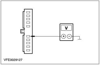
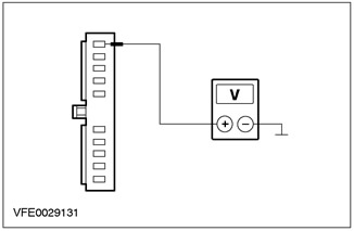
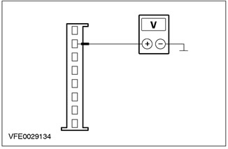
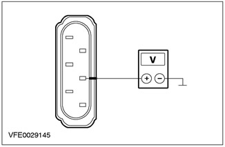
6 Measure the voltage between pin 5 of connector C836, left headlight, circuit 64-LE45 (blue), from the wiring side, and "ground". |
|
• Does the detected voltage change according to the setting of the headlight range adjustment switch? |
|
|
→ Yes |
|
|
Go to P4 |
|
|
→ No |
|
|
REPAIR open circuit 64-LE45 using the wiring diagrams (blue) between splice S106 and headlight. Check the correct operation of the system. |
|
|
P4: LEFT HEADLIGHT HEALING MOTOR GROUND CIRCUIT INSPECTION |
|
|
1 Enter the OFF position. |
|

|
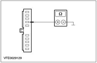
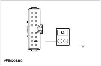
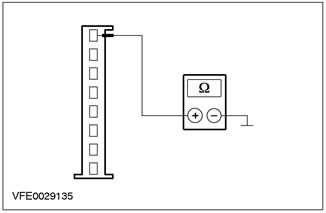
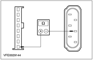
2 Measure the resistance between pin 7 of connector C836, left headlight, circuit 91-LE45 (yellow-blue), from the wiring side, and "ground". |
|
• Is the resistance less than 2 ohms? |
|
|
→ Yes |
|
|
Go to P5 |
|
|
→ No |
|
|
REPAIR open circuit 91-LE45 using the wiring diagrams (yellow-blue) between headlight and splice S118. Check the correct operation of the system. |
|
|
P5: LEFT HEADLIGHT HEALING MOTOR CIRCUIT TEST |
|
|
1 Enter the OFF position. |
|
|
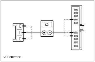
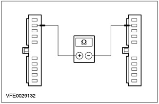
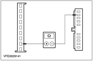
2 Measure the resistance of all circuits between the headlight beam leveling motor connector C2000, wiring side, and the corresponding pin on the left headlight connector C836, component side. |
|
• Is the result of each resistance measurement greater than 2 ohms? |
|
|
→ Yes |
|
|
INSPECT headlight beam leveling motor for mechanical damage. INSTALL a new one if necessary. Check the correct operation of the system. |
|
|
→ No |
|
|
REPAIR the relevant circuit using the wiring diagrams. Check the correct operation of the system. |
|
|
P6: CHECK THE ELECTRICAL POWER CIRCUIT OF THE RIGHT HEADLIGHT |
|
|
1 Turn on the PARKING LIGHTS. |
|
|
2 Check the right parking light. |
|
|
• Is the parking light on? |
|
|
→ Yes |
|
|
Go to P7 |
|
|
→ No |
|
|
Section 417-01 Parking Lights, Tail Lights, and License Plate Lamps |
|
|
P7: RIGHT HEADLIGHT TILT CONTROL CIRCUIT CHECK |
|
|
1 Enter the OFF position. |
|
|
2 Disconnect the C837 right headlight. |
|
|
3 Drive the ON position. |
|
|
4 Turn on the low beam headlights. |
|
|
5 Adjust the HEADLIGHT TILT CORRECTION. |
|

|
6 Measure the voltage between pin 5 of connector C837 of the right headlight, circuit 64-LE46 (red-blue), from the wiring side, and "ground". |
|
• Does the detected voltage change according to the setting of the headlight range adjustment switch? |
|
|
→ Yes |
|
|
Go to P8 |
|
|
→ No |
|
|
REPAIR open circuit 64-LE46 using the wiring diagrams (red-blue) between splice S106 and headlight. Check the correct operation of the system. |
|
|
P8: LEFT HEADLIGHT HEALING MOTOR GROUND CIRCUIT CHECK |
|
|
1 Enter the OFF position. |
|
|
2 Measure the resistance between pin 7 of connector C837, right headlight, circuit 91-LE46 (black and blue), from the wiring side, and "ground". |
|
• Is the resistance less than 2 ohms? |
|
|
→ Yes |
|
|
Go to P9 |
|
|
→ No |
|
|
REPAIR open circuit 91-LE46 using the wiring diagrams (black and blue) between headlight and splice S118. Check the correct operation of the system. |
|
|
P9: CHECKING THE ELECTRICAL ELECTRICAL MOTOR CIRCUIT OF THE RIGHT HEADLIGHT |
|
|
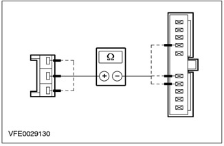
1 Measure the resistance of all circuits between the headlight beam tilt motor connector C2001, wiring side, and the corresponding pin on the left headlight connector C837, component side. |
|
• Is the result of each resistance measurement greater than 2 ohms? |
|
|
→ Yes |
|
|
INSPECT headlight beam leveling motor for mechanical damage. INSTALL a new one if necessary. Check the correct operation of the system. |
|
|
→ No |
|
|
REPAIR the relevant circuit using the wiring diagrams. Check the correct operation of the system. |
|
|
P10: 91-DA3 ELECTRICAL CIRCUIT CHECK (BLACK AND ORANGE) FOR A BREAK |
|
|
1 Enter the OFF position. |
|
|
2 Disconnect the left headlight C836. |
|

|
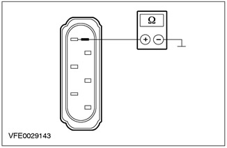
3 Measure the resistance between pin 7 of connector C836, left headlight, circuit 91-LE45 (yellow-blue), from the wiring side, and "ground". |
|
• Is the resistance less than 2 ohms? |
|
|
→ Yes |
|
|
Go to P11 |
|
|
→ No |
|
|
REPAIR open circuit 91-DA3 using the wiring diagrams (BK/OG) between splice S118 and earth point G1. Check the correct operation of the system. |
|
|
P11: LIGHT SWITCH TEST |
|
|
1 Disconnect the C320 light switch. |
|
|
2 Check the light switch according to chap. "Checking the elements", attached to the wiring diagrams. |
|
|
• Is the light switch OK? |
|
|
→ Yes |
|
|
Go to P12 |
|
|
→ No |
|
|
INSTALL a new light switch. Check the correct operation of the system. |
|
|
P12: LIGHT SWITCH GROUND ELECTRICAL CHECK |
|
|
1 Measure the resistance between pin 10 of connector C320, light switch, circuit 31-LE29 (black), from the wiring side, and "ground". |
|
• Is the resistance less than 2 ohms? |
|
|
→ Yes |
|
|
REPAIR open circuit 64-LE1 using the wiring diagrams (blue) between light switch and splice S106. Check the correct operation of the system. |
|
|
→ No |
|
|
REPAIR open circuit 31-LE29 using the wiring diagrams (black) and respectively 31-DA2 (black), between the light switch and earth point G14. Check the correct operation of the system. |
|
PINPOINT TEST Q: HEADLIGHT CORRECTION NOT WORKING/INCORRECTLY, XENON HEADLIGHTS
|
STATES |
DETAILS/RESULTS/ACTIONS |
|
Q1: SYSTEM CHECK USING WDS |
|
|
1 Enter the OFF position. |
|
|
2 Connect the diagnostic tool. |
|
|
3 Check the system using WDS |
|
|
• Are there any DTCs (DTC)? |
|
|
→ Yes |
|
|
Take appropriate action on DTCs as directed by WDS. CLEAR fault memory and CHECK system for correct operation. |
|
|
→ No |
|
|
Go to Q2 |
|
|
Q2: IDENTIFY THE STATE IN WHICH THE PROBLEM APPEARS. |
|
|
1 Drive the ON position. |
|
|
2 Turn on the low beam headlights. |
|
|
3 Simulate the state of an unloaded and, accordingly, a fully loaded car. |
|
|
4 Check the adjustment of the xenon headlights. |
|
|
• Are both xenon headlights not adjustable? |
|
|
→ Yes |
|
|
Go to Q9 |
|
|
→ No |
|
|
Left xenon headlight not adjustable: Go to Q3 |
|
|
Right xenon headlight not adjustable: Go to Q6 |
|
|
Q3: CHECKING THE VOLTAGE IN THE ELECTRICAL CIRCUIT OF THE LEFT XENON HEADLIGHT |
|
|
1 Enter the OFF position. |
|
|
2 Disconnect the C836 left xenon headlight. |
|
|
3 Drive the ON position. |
|
|
4 Turn on the low beam headlights. |
|
|
5 Measure the voltage between pin 10 of connector C836 of the left xenon headlight circuit 15-XL28A (green-orange), from the wiring side, and "ground". |
|
• Does the battery voltage register? |
|
|
→ Yes |
|
|
Go to Q4 |
|
|
→ No |
|
|
REPAIR open circuit 15-XL28A using the wiring diagrams (green-orange) between xenon headlight and splice S114. Check the correct operation of the system. |
|
|
Q4: CHECKING THE GROUND CIRCUIT OF THE LEFT XENON HEADLIGHT |
|
|
1 Enter the OFF position. |
|

|
2 Measure the resistance between pin 7 of connector C836 of the left xenon headlight circuit 91-LE45 (yellow-blue), from the wiring side, and "ground". |
|
• Is the resistance less than 2 ohms? |
|
|
→ Yes |
|
|
Go to Q5 |
|
|
→ No |
|
|
REPAIR open circuit 91-LE45 using the wiring diagrams (yellow-blue) between the left xenon headlight and splice S118. Check the correct operation of the system. |
|
|
Q5: 63-LE45 ELECTRICAL CONTROL CIRCUIT CHECK (WHITE) FOR A BREAK |
|
|
1 Disconnect the C837 right xenon headlight. |
|
|
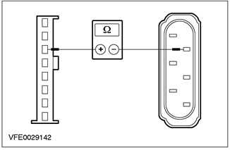
2 Measure the resistance between pin 9 of connector C836 of the left xenon headlight circuit 63-LE45 (white), on the wiring side, and pin 9 of connector C837 of the right xenon headlight, circuit 63-LE46 (white-red), from the side of the electrical wiring. |
|
• Is the resistance less than 2 ohms? |
|
|
→ Yes |
|
|
CHECK the xenon headlight, INSTALL a new one if necessary. Check the correct operation of the system. |
|
|
→ No |
|
|
REPAIR open circuit 63-LE45 using the wiring diagrams (white) between xenon headlight and splice S105. Check the correct operation of the system. |
|
|
Q6: CHECKING THE POWER SUPPLY OF THE RIGHT XENON HEADLIGHT |
|
|
1 Enter the OFF position. |
|
|
2 Disconnect the C837 right xenon headlight. |
|
|
3 Drive the ON position. |
|
|
4 Turn on the low beam headlights. |
|

|
5 Measure the voltage between pin 10 of connector C837 of the right xenon headlight circuit 15-XL28B (green-orange), from the wiring side, and "ground". |
|
• Does the battery voltage register? |
|
|
→ Yes |
|
|
Go to Q7 |
|
|
→ No |
|
|
REPAIR open circuit 15-XL28B using the wiring diagrams (green-orange) between xenon headlight and splice S114. Check the correct operation of the system. |
|
|
Q7: CHECKING THE GROUND CIRCUIT OF THE RIGHT XENON HEADLIGHT |
|
|
1 Enter the OFF position. |
|

|
2 Measure the resistance between pin 7 of connector C837 of the right xenon headlight circuit 91-LE46 (black and blue), from the wiring side, and "ground". |
|
• Is the resistance less than 2 ohms? |
|
|
→ Yes |
|
|
Go to Q8 |
|
|
→ No |
|
|
REPAIR open circuit 91-LE46 using the wiring diagrams (black and blue) between the right xenon headlight and splice S118. Check the correct operation of the system. |
|
|
Q8: 63-LE46 ELECTRICAL CONTROL CIRCUIT CHECK (WHITE-RED) FOR A BREAK |
|
|
1 Disconnect the C836 left xenon headlight. |
|

|
2 Measure the resistance between pin 9 of connector C836 of the left xenon headlight circuit 63-LE45 (white), on the wiring side, and pin 9 of connector C837 of the right xenon headlight, circuit 63-LE46 (white-red), from the side of the electrical wiring. |
|
• Is the resistance less than 2 ohms? |
|
|
→ Yes |
|
|
CHECK the xenon headlight, INSTALL a new one if necessary. Check the correct operation of the system. |
|
|
→ No |
|
|
REPAIR open circuit 63-LE46 using the wiring diagrams (white-red) between xenon headlight and splice S105. Check the correct operation of the system. |
|
|
Q9: CHECK THE POWER SUPPLY OF THE XENON HEADLIGHT CONTROL MODULE / HEADLIGHT TILT SENSOR |
|
|
1 Enter the OFF position. |
|
|
2 Disconnect the C838 xenon headlight control module/headlight range sensor. |
|
|
3 Drive the ON position. |
|
|
4 Turn on the low beam headlights. |
|
|
5 Measure the voltage between pin 6 of connector C838 of the xenon headlight control module/headlight range sensor circuit 15S-LE19C (green-blue), from the wiring side, and "ground". |
|
• Does the battery voltage register? |
|
|
→ Yes |
|
|
Go to Q10 |
|
|
→ No |
|
|
REPAIR open circuit 15S-LE19C using the wiring diagrams (green-blue) between xenon headlight control module/headlight range sensor and splice S134. Check the correct operation of the system. |
|
|
Q10: CHECK THE POWER SUPPLY OF THE XENON HEADLIGHT CONTROL MODULE / HEADLIGHT TILT SENSOR |
|
|
1 Measure the voltage between pin 2 of connector C838 of the xenon headlight control module/headlight range sensor, circuit 15-XL28C (green-orange), from the wiring side, and "ground". |
|
• Does the battery voltage register? |
|
|
→ Yes |
|
|
Go to Q13 |
|
|
→ No |
|
|
Go to Q11 |
|
|
Q11: CHECK FUSE F53 (CJB) |
|
|
1 Enter the OFF position. |
|
|
2 CHECK Fuse F53 (CJB). |
|
|
3 Check fuse F53 (10 A) |
|
|
• Is the fuse good? |
|
|
→ Yes |
|
|
Go to Q12 |
|
|
→ No |
|
|
INSTALL a new fuse F53 (10 A) and CHECK the system is working properly. If the fuse blows again, LOCATE and REPAIR the short circuit using the wiring diagrams. Check the correct operation of the system. |
|
|
Q12: CHECK THE VOLTAGE IN THE FUSE F53 (CJB) |
|
|
1 Connect Fuse F53 (CJB). |
|
|
2 Drive the ON position. |
|
|
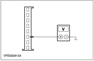
3 Measure the voltage between F53 (CJB) and "mass". |
|
|
• Does the battery voltage register? |
|
|
→ Yes |
|
|
REPAIR open circuit 15-XL28C using the wiring diagrams (green-orange), 15-LG28A (green-white) and 15-LG28 (green-white) between the xenon headlight control module/headlight range sensor and fuse F53. Check the correct operation of the system. |
|
|
→ No |
|
|
Using the wiring diagrams, LOCATE and REPAIR the F53 fuse supply circuit, CHECK the CJB if necessary and INSTALL a new one. Check the correct operation of the system. |
|
|
Q13: CHECK THE XENON HEADLIGHT CONTROL MODULE/ HEADLIGHT TILT SENSOR GROUND CIRCUIT |
|
|
1 Enter the OFF position. |
|
|
2 Measure the resistance between C838 pin 1 of the xenon headlight control module/headlight range sensor, circuit 91-XL31 (black and blue), from the wiring side, and "ground". |
|
• Is the resistance less than 2 ohms? |
|
|
→ Yes |
|
|
Go to Q14 |
|
|
→ No |
|
|
REPAIR open circuit 91-XL31 using the wiring diagrams (black and blue) between the xenon headlight control module/headlight range sensor and earth point G1. Check the correct operation of the system. |
|
|
Q14: 63-LE1 ELECTRICAL CONTROL CIRCUIT CHECK (WHITE) FOR A BREAK |
|
|
1 Disconnect the C836 left xenon headlight. |
|
|
2 Measure the resistance between pin 7 of connector C838 of the xenon headlight control module/headlight range sensor, circuit 63-LE1 (white), on the wiring side, and pin 9 of connector C836 of the left xenon headlight, circuit 63-LE45 (white), from the side of the electrical wiring,. |
|
• Is the resistance less than 2 ohms? |
|
|
→ Yes |
|
|
Go to Q15 |
|
|
→ No |
|
|
REPAIR open circuit 63-LE1 using the wiring diagrams (white) between xenon headlight control module/headlight range sensor and splice S105. Check the correct operation of the system. |
|
|
Q15: 8-XL10 ELECTRICAL CIRCUIT CHECK (WHITE) FOR A BREAK |
|
|
1 Enter the OFF position. |
|
|
2 Disconnect the C839 rear headlight range sensor. |
|
|
3 Measure the resistance between C838 pin 3 of the xenon headlight control module/headlight range sensor, circuit 8-XL10 (white), on the wiring side, and pin 4 of the C839 connector of the rear headlight range sensor, circuit 8-XL10 (white), from the side of the electrical wiring,. |
|
• Is the resistance less than 2 ohms? |
|
|
→ Yes |
|
|
Go to Q16 |
|
|
→ No |
|
|
REPAIR open circuit 8-XL10 using the wiring diagrams (white) between the xenon headlight control module/headlight range sensor and the rear headlight range sensor. Check the correct operation of the system. |
|
|
Q16: 7-XL10 ELECTRICAL CIRCUIT CHECK (YELLOW) FOR A BREAK |
|
|
1 Measure the resistance between pin 8 of connector C838 of the xenon headlight control module/headlight range sensor, circuit 7-XL10 (yellow), on the wiring side, and pin 5 of connector C839, rear headlight range sensor, circuit 7-XL10 (yellow), from the side of the electrical wiring,. |
|
• Is the resistance less than 2 ohms? |
|
|
→ Yes |
|
|
Go to Q17 |
|
|
→ No |
|
|
REPAIR open circuit 7-XL10 using the wiring diagrams (yellow) between the xenon headlight control module/headlight range sensor and the rear headlight range sensor. Check the correct operation of the system. |
|
|
Q17: REAR HEADLIGHT SENSOR GROUND CIRCUIT CHECK |
|
|
1 Measure the resistance between C839 connector pin 1, rear headlight range sensor, circuit 91-XL10 (yellow-blue), from the wiring side, and "ground". |
|
• Is the resistance less than 2 ohms? |
|
|
→ Yes |
|
|
Go to Q18 |
|
|
→ No |
|
|
REPAIR open circuit 91-XL10 using the wiring diagrams (yellow-blue) between rear headlight range sensor and splice S118. Check the correct operation of the system. |
|
|
Q18: REAR HEADLIGHT SENSOR POWER CIRCUIT CHECK |
|
|
1 Connect the C838 xenon headlight control module/headlight range sensor. |
|
|
2 Drive the ON position. |
|
|
3 Turn on the low beam headlights. |
|
|
4 Measure the voltage between pin 5 of connector C839, rear headlight range sensor, circuit 8-XL10 (white), from the wiring side, and "ground". |
|
• Is 5V registered? |
|
|
→ Yes |
|
|
INSTALL a new rear headlight range sensor. CHECK the system is working properly. |
|
|
→ No |
|
|
INSTALL a new xenon headlight control module/headlight range sensor. CHECK the system is working properly. |
|
Visitor comments