|
STATES |
DETAILS/RESULTS/ACTIONS |
|
H1: FUSE CHECK F59 (CJB) |
|
|
1 Enter the OFF position. |
|
|
2 CHECK Fuse F59 (CJB). |
|
|
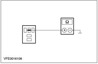
3 Check fuse F59 (7.5 A). |
|
|
• Is the fuse good? |
|
|
→ Yes |
|
|
Go to H2 |
|
|
→ No |
|
|
INSTALL a new fuse F59 (7.5 A) and CHECK the system is working properly. If the fuse blows again, LOCATE and REPAIR the short circuit using the wiring diagrams. Check the correct operation of the system. |
|
|
H2: F59 FUSE VOLTAGE CHECK (CJB) |
|
|
1 Connect Fuse F59 (CJB). |
|
|
2 Drive the ON position. |
|
|
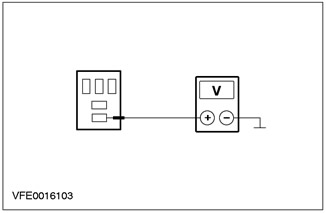
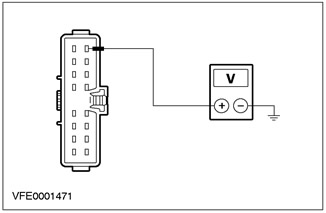
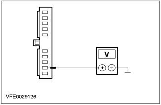
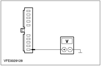
3 Measure the voltage between fuse F59 and "weight". |
|
|
• Does the battery voltage register? |
|
|
→ Yes |
|
|
Go to H3 |
|
|
→ No |
|
|
Using the wiring diagrams, RESTORE power to fuse F59. If necessary, INSTALL a new CJB. Check the correct operation of the system. |
|
|
H3: CJB CHECK |
|
|
1 Enter the OFF position. |
|
|
2 Disconnect the C1006 low beam relay. |
|
|
3 Drive the ON position. |
|
|
4 Turn on the low beam headlights. |
|

|
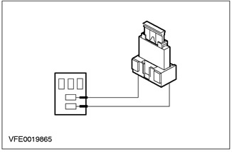
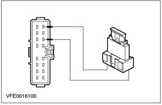
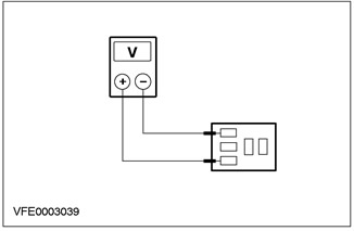
5 Measure the voltage between pin 1 of connector C1006 of the low beam relay, circuit 15S-LE19 (B/D) (green-blue), from the BJB side, and "mass". |
|
• Does the battery voltage register? |
|
|
→ Yes |
|
|
Using the wiring diagrams, REPAIR the relay ground circuit between splice S118 (earth point G1) and ground point G1. Check the correct operation of the system. |
|
|
→ No |
|
|
CHECK CJB (open circuit between fuse F59 and pin 9 of connector C16), if necessary, INSTALL a new one. Check the correct operation of the system. |
|
PINPOINT TEST I: LOW BEAM DOES NOT WORK
|
STATES |
DETAILS/RESULTS/ACTIONS |
|
I1: FUSE CHECK F22 BJB. |
|
|
1 Enter the OFF position. |
|
|
2 CHECK Fuse F22 (BJB). |
|
|
3 Check fuse F22 (30 A). |
|
|
• Is the fuse good? |
|
|
→ Yes |
|
|
Go to I2 |
|
|
→ No |
|
|
Install new fuse F22 (30 A). If the fuse blows again, refer to the wiring diagrams, FIND and REPAIR the short circuit. Verify that the system is operating correctly. |
|
|
I2: FUSE VOLTAGE CHECK F22 (BJB) |
|
|
1 Connect Fuse F22 (BJB). |
|
|
2 Drive the ON position. |
|
|
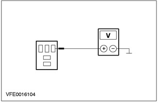
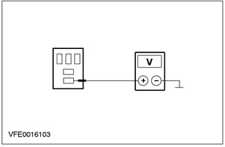
3 Measure the voltage between fuse F22 and "weight". |
|
|
• Does the battery voltage register? |
|
|
→ Yes |
|
|
Go to I3 |
|
|
→ No |
|
|
CHECK BJB, INSTALL a new one if necessary. Check the correct operation of the system. |
|
|
I3: CHECKING THE VOLTAGE IN THE DOWN-BEAM RELAY |
|
|
1 Enter the OFF position. |
|
|
2 Disconnect the C1006 low beam relay. |
|
|
3 Drive the ON position. |
|
|
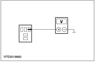
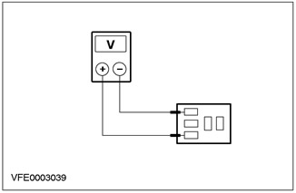
4 Measure voltage between pin 3 of connector C1006 low beam relay, circuit 30-LE20 (red), from the BJB side, and "mass". |
|
• Does the battery voltage register? |
|
|
→ Yes |
|
|
Go to I4 |
|
|
→ No |
|
|
REPAIR open circuit 30-LE20 using the wiring diagrams (red), between F22 (BJB) and low beam relay. Check the correct operation of the system. |
|
|
I4: CHECK THE LOW BEAM RELAY CONTROL CIRCUIT |
|
|
1 Drive the ON position. |
|
|
2 Turn on the low beam headlights. |
|
|
3 Measure the voltage between pin 1 of connector C1006 low beam relay circuit 15S-LE19B/D (green-red), from the BJB side, and "mass". |
|
• Does the battery voltage register? |
|
|
→ Yes |
|
|
Vehicles with DRL option: Go to I5 |
|
|
Vehicles without DRL option: Go to I7 |
|
|
→ No |
|
|
Go to I8 |
|
|
I5: CHECKING THE ELECTRICAL SUPPLY CIRCUIT OF THE LOW-BEAM RELAY |
|
|
1 Install fusible jumper wire (30 A) into connector C1006 low beam relay, between pin 3, circuit 30-LE20 (red), and pin 5, electric circuit 15S-LE20 (green-red), by BJB. |
|
2Check low beam headlights. |
|
|
• Are the low beam headlights on? |
|
|
→ Yes |
|
|
Go to I7 |
|
|
→ No |
|
|
Go to I6 |
|
|
I6: 15S-LE20 ELECTRICAL CIRCUIT CHECK (GREEN_RED) BETWEEN LOW BEAM RELAY AND DAYTIME HEADLAMP RELAY (DRL) |
|
|
1 Enter the OFF position. |
|
|
2 Connect the C1006 low beam relay. |
|
|
3 Disconnect C1012 daytime running lamp relay (DRL). |
|
|
4 Drive the ON position. |
|
|
5 Turn on the low beam headlights. |
|
|
6 Measure voltage between pin 4 of connector C1012 of the daytime running lamp relay (DRL), electrical circuit 15S-LE20 (green-red), from the BJB side, and "mass". |
|
• Does the battery voltage register? |
|
|
→ Yes |
|
|
INSTALL a new daytime running lamp relay (DRL). Check the correct operation of the system. |
|
|
→ No |
|
|
REPAIR open circuit 15S-LE20 using the wiring diagrams (green-red), between low beam relay and daytime running lamp relay (DRL). Check the correct operation of the system. |
|
|
I7: GROUND CHECK OF THE LOW-BEAM RELAY |
|
|
1 Enter the OFF position. |
|

|
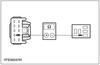
2 Measure the resistance of the circuit between pin 2 of the low beam relay connector C1006, circuit 91-LE19 (black and blue), from the BJB side, and "mass". |
|
• Is the resistance less than 2 ohms? |
|
|
→ Yes |
|
|
INSTALL a new low beam relay. Check the correct operation of the system. |
|
|
→ No |
|
|
REPAIR open circuit 91-LE19 using the wiring diagrams (black and blue), between low beam relay and splice S118 (earth point G1). Check the correct operation of the system. |
|
|
I8: LIGHT SWITCH VOLTAGE CHECK |
|
|
1 Enter the OFF position. |
|
|
2 Disconnect the C320 light switch. |
|
|
3 Drive the ON position. |
|
|
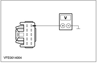
4 Measure the voltage between pin 8 of connector C320, light switch, circuit 15-LE29 (green-black), from the wiring side, and "ground". |
|
• Does the battery voltage register? |
|
|
→ Yes |
|
|
Go to I9 |
|
|
→ No |
|
|
REPAIR open circuit 15-LE29 using the wiring diagrams (green-black), between fuse F59 (CJB) and light switch. Check the correct operation of the system. |
|
|
I9: LIGHT SWITCH TEST |
|
|
1 Enter the OFF position. |
|
|
2 Install fusible jumper wire (7,5 A) into connector C320 of the light switch, between pin 8, circuit 15-LE29 (green-black), and pin 6, electrical circuits 15S-LE14 (A/B) (green-red), 15S-LE19 (green-blue) respectively, 15S-LE19 (green-blue), 15S-LE19C (green-blue), from the side of the electrical wiring. |
|
3 Drive the ON position. |
|

|
4 Measure the voltage between pin 1 of connector C1006 low beam relay circuit 15S-LE19B/D (green-blue), from the BJB side, and "mass". |
|
• Does the battery voltage register? |
|
|
→ Yes |
|
|
INSTALL a new light switch. Check the correct operation of the system. |
|
|
→ No |
|
|
REPAIR the open circuit using the wiring diagrams (green-blue), between the light switch and the low beam relay. Check the correct operation of the system. |
|
PINPOINT TEST J: HIGH BEAM DOES NOT WORK
|
STATES |
DETAILS/RESULTS/ACTIONS |
|
J1: HIGH BEAM RELAY VOLTAGE TEST |
|
|
1 Enter the OFF position. |
|
|
2 Disconnect the C1005 high beam relay. |
|
|
3 Drive the ON position. |
|
|
4 Measure voltage between pin 3 of connector C1005 high beam relay circuit 30-LE13 (red), from the BJB side, and "mass". |
|
• Does the battery voltage register? |
|
|
→ Yes |
|
|
Go to J2 |
|
|
→ No |
|
|
REPAIR open circuit 30-LE13 using the wiring diagrams (red), between splice S102 (battery powered) and high beam relay. Check the correct operation of the system. |
|
|
J2: CHECKING THE CONTROL VOLTAGE IN THE HIGH BEAM RELAY |
|
|
1 Turn on the high beam. |
|
|
2 Measure the voltage between pin 1 of connector C1005 high beam relay circuit 15S-LE12 (green-yellow), from the BJB side, and "mass". |
|
• Does the battery voltage register? |
|
|
→ Yes |
|
|
Go to J3 |
|
|
→ No |
|
|
Go to J4 |
|
|
J3: HIGH BEAM RELAY GROUND ELECTRICAL CHECK |
|
|
1 Enter the OFF position. |
|
|
2 Measure the resistance between pin 2 of connector C1005 high beam relay circuit 91-LE12 (black and yellow), from the BJB side, and "mass". |
|
• Is the resistance less than 2 ohms? |
|
|
→ Yes |
|
|
INSTALL a new high beam relay. Check the correct operation of the system. |
|
|
→ No |
|
|
REPAIR open circuit 91-LE12 using the wiring diagrams (black and yellow), between high beam relay and splice S118 (earth point G1). Check the correct operation of the system. |
|
|
J4: MULTI-FUNCTION SWITCH TEST |
|
|
1 Enter the OFF position. |
|
|
2 Disconnect the C459 multifunction switch. |
|
|
3 Install fusible jumper wire (7,5 A) in connector C459 of the multifunction switch, between pin 6, circuit 15-LE14 (green-red), and pin 7, electric circuit 15S-LE12 (green-yellow), from the side of the electrical wiring. |
|
4 Drive the ON position. |
|

|
5 Measure the voltage between pin 1 of connector C1005 high beam relay circuit 15S-LE12 (green-yellow), from the BJB side, and "mass". |
|
• Does the battery voltage register? |
|
|
→ Yes |
|
|
INSTALL a new multifunction switch. Check the correct operation of the system. |
|
|
→ No |
|
|
Go to J5 |
|
|
J5: HIGH BEAM RELAY CONTROL CIRCUIT CHECK |
|
|
1 Enter the OFF position. |
|
|
2 Measure the resistance between pin 7 of connector C459 of the multifunction switch, circuit 15S-LE12 (green-yellow), wiring side, and pin 1 of connector C1005 high beam relay, circuit 15S-LE12 (green-yellow), by BJB. |
|
• Is the resistance less than 2 ohms? |
|
|
→ Yes |
|
|
REPAIR open circuit 15-LE14 using the wiring diagrams (green-red), between fuse F59 (CJB) and multifunction switch. Check the correct operation of the system. |
|
|
→ No |
|
|
REPAIR open circuit 15S-LE12 using the wiring diagrams (green-yellow), between the multifunction switch and the high beam relay. Check the correct operation of the system. |
|
PINPOINT TEST K: ONE LOW BEAM HEADLIGHT DOES NOT WORK (HIGH BEAM HEADLIGHTS OK)
|
STATES |
DETAILS/RESULTS/ACTIONS |
|
K1: DETECTION OF A FAULTY LOW-BEAM HEADLIGHT |
|
|
1 Identify the faulty low beam headlight. |
|
|
• Left low beam not working? |
|
|
→ Yes |
|
|
Go to K2 |
|
|
→ No |
|
|
Right low beam headlight: Go to K5 |
|
|
K2: FUSE CHECK F16 BJB. |
|
|
1 Enter the OFF position. |
|
|
2 CHECK Fuse F16 (BJB). |
|
|
3 Check fuse F16 (15 A) |
|
|
• Is the fuse good? |
|
|
→ Yes |
|
|
Go to K3 |
|
|
→ No |
|
|
Install new fuse F16 (15 A). If the fuse blows again, LOCATE and REPAIR the short circuit using the wiring diagrams. Check the correct operation of the system. |
|
|
K3: FUSE VOLTAGE CHECK F16 (BJB) |
|
|
1 Connect Fuse F16 (BJB). |
|
|
2 Drive the ON position. |
|
|
3 Turn on the low beam headlights. |
|
|
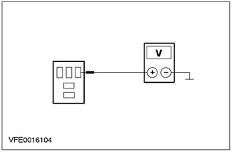
4 Measure the voltage between fuse F16 and "weight". |
|
|
• Does the battery voltage register? |
|
|
→ Yes |
|
|
Go to K4 |
|
|
→ No |
|
|
REPAIR open circuit 15S-DC16 using the wiring diagrams (green-blue), between the dipped beam relay and respectively the daytime running lamp relay (DRL) (with option for DRL) and fuse F16. Check the correct operation of the system. |
|
|
K4: LEFT LOW BEAM VOLTAGE CHECK |
|
|
1 Enter the OFF position. |
|
|
2 Disconnect Left headlight (C836). |
|
|
3 Drive the ON position. |
|
|
4 Turn on the low beam headlights. |
|

|
5 Measure the voltage between pin 2 of connector C836, left headlight, circuit 15S-LE16 (green-orange), from the wiring side, and "ground". |
|
• Does the battery voltage register? |
|
|
→ Yes |
|
|
CHECK the headlight, INSTALL a new one if necessary. Check the correct operation of the system. |
|
|
→ No |
|
|
REPAIR open circuit 15S-LE16 using the wiring diagrams (GN/OG), between fuse F16 and the left headlight. Check the correct operation of the system. |
|
|
K5: FUSE CHECK F17 BJB. |
|
|
1 Enter the OFF position. |
|
|
2 CHECK Fuse F17 (BJB). |
|
|
3 Check fuse F17 (15 A) |
|
|
• Is the fuse good? |
|
|
→ Yes |
|
|
Go to K6 |
|
|
→ No |
|
|
Install new fuse F17 (15 A). If the fuse blows again, LOCATE and REPAIR the short circuit using the wiring diagrams. Check the correct operation of the system. |
|
|
K6: FUSE VOLTAGE CHECK F17 (BJB) |
|
|
1 Connect Fuse F17 (BJB). |
|
|
2 Drive the ON position. |
|
|
3 Turn on the low beam headlights. |
|
|
4 Measure the voltage between fuse F17 and "weight". |
|
|
• Does the battery voltage register? |
|
|
→ Yes |
|
|
Go to K7 |
|
|
→ No |
|
|
REPAIR open circuit 15S-DC17 using the wiring diagrams (GN/BU), between low beam relay respectively daytime running lamp relay (DRL) (with option for DRL) and fuse F17. Check the correct operation of the system. |
|
|
K7: VOLTAGE CHECK IN THE ELECTRICAL CIRCUIT OF THE LOW BEAM HEADLIGHT RIGHT |
|
|
1 Enter the OFF position. |
|
|
2 Disconnect Right Headlight (C837). |
|
|
3 Drive the ON position. |
|
|
4 Turn on the low beam headlights. |
|
|
5 Measure the voltage between pin 2 of connector C837 of the right headlight, circuit 15S-LE23 (green-white), from the wiring side, and "ground". |
|
• Does the battery voltage register? |
|
|
→ Yes |
|
|
CHECK the headlight, INSTALL a new one if necessary. Check the correct operation of the system. |
|
|
→ No |
|
|
REPAIR open circuit 15S-LE23 using the wiring diagrams (green-white), between the fuse F17 and the right headlight. Check the correct operation of the system. |
|
PINPOINT TEST L: ONE HIGH BEAM HEADLIGHT DOES NOT WORK (LOW BEAM FARV OK)
|
STATES |
DETAILS/RESULTS/ACTIONS |
|
L1: DEFECTIVE HIGH BEAM DETECTION |
|
|
1 Identify the faulty high beam headlight. |
|
|
• Left high beam headlight not working? |
|
|
→ Yes |
|
|
Go to L2 |
|
|
→ No |
|
|
Right high beam: Go to L5 |
|
|
L2: FUSE CHECK F26 BJB. |
|
|
1 Enter the OFF position. |
|
|
2 CHECK Fuse F26 (BJB). |
|
|
3 Check fuse F26 (10 A) |
|
|
• Is the fuse good? |
|
|
→ Yes |
|
|
Go to L3 |
|
|
→ No |
|
|
Install new fuse F26 (10 A). If the fuse blows again, LOCATE and REPAIR the short circuit using the wiring diagrams. Check the correct operation of the system. |
|
|
L3: CHECK THE VOLTAGE IN FUSE AREA F26 |
|
|
1 Connect Fuse F26 (BJB). |
|
|
2 Drive the ON position. |
|
|
3 Turn on the low beam headlights. |
|
|
4 Turn on the high beam. |
|
|
5 Measure the voltage between fuse F26 and "weight". |
|
|
• Does the battery voltage register? |
|
|
→ Yes |
|
|
Go to L4 |
|
|
→ No |
|
|
REPAIR open circuit 15S-DC26 using the wiring diagrams (green-blue), between high beam relay and fuse F26. Check the correct operation of the system. |
|
|
L4: LEFT HIGH BEAM VOLTAGE CHECK |
|
|
1 Enter the OFF position. |
|
|
2 Disconnect Left headlight (C836). |
|
|
3 Drive the ON position. |
|
|
4 Turn on the low beam headlights. |
|
|
5 Turn on the high beam. |
|
|
6 Measure the voltage between pin 1 of connector C836, left headlight, circuit 15S-LE15 (green-black), from the wiring side, and "ground". |
|
• Does the battery voltage register? |
|
|
→ Yes |
|
|
CHECK the headlight, INSTALL a new one if necessary. Check the correct operation of the system. |
|
|
→ No |
|
|
REPAIR open circuit 15S-LE15 using the wiring diagrams (green-black), between fuse F26 and the left headlight. Check the correct operation of the system. |
|
|
L5: FUSE CHECK F27 BJB |
|
|
1 Enter the OFF position. |
|
|
2CHECK Fuse F27 (BJB). |
|
|
3 Check fuse F27 (10 A) |
|
|
• Is the fuse good? |
|
|
→ Yes |
|
|
Go to L6 |
|
|
→ No |
|
|
Install new fuse F27 (10 A). If the fuse blows again, LOCATE and REPAIR the short circuit using the wiring diagrams. Check the correct operation of the system. |
|
|
L6: FUSE VOLTAGE CHECK F27 (BJB) |
|
|
1 Connect Fuse F27 (BJB). |
|
|
2 Drive the ON position. |
|
|
3 Turn on the low beam headlights. |
|
|
4 Turn on the high beam. |
|
|
5 Measure the voltage between fuse F27 and "weight". |
|
|
• Does the battery voltage register? |
|
|
→ Yes |
|
|
Go to L7 |
|
|
→ No |
|
|
REPAIR open circuit 15S-DC27 using the wiring diagrams (GN/BU), between high beam relay and fuse F27. Check the correct operation of the system. |
|
|
L7: VOLTAGE TEST IN HIGH BEAM CIRCUIT RIGHT |
|
|
1 Enter the OFF position. |
|
|
2 Disconnect Right Headlight (C837). |
|
|
3 Drive the ON position. |
|
|
4 Turn on the low beam headlights. |
|
|
5 Turn on the high beam. |
|

|
6 Measure the voltage between pin 1 of connector C837 of the right headlight, circuit 15S-LE22 (green-orange), from the wiring side, and "ground". |
|
• Does the battery voltage register? |
|
|
→ Yes |
|
|
CHECK the headlight, INSTALL a new one if necessary. Check the correct operation of the system. |
|
|
→ No |
|
|
REPAIR open circuit 15S-LE22 using the wiring diagrams (green-orange), between fuse F27 and the right headlight. Check the correct operation of the system. |
|
PINPOINT TEST M: HEADLIGHTS STILL ON
|
STATES |
DETAILS/RESULTS/ACTIONS |
|
M1: DETERMINING THE STATE IN WHICH THE FAULT IS APPEARING |
|
|
1 Drive the ON position. |
|
|
2 Turn off the lights. |
|
|
3Check the headlights. |
|
|
• Is the high beam on permanently? |
|
|
→ Yes |
|
|
Go to M11 |
|
|
→ No |
|
|
Low Beam Headlamps: Go to M2 |
|
|
M2: DETERMINATION OF SHORT CIRCUIT ON THE ELECTRICAL POWER CIRCUIT |
|
|
1 Enter the OFF position. |
|
|
2 Disconnect Fuse F16 (BJB). |
|
|
3 Disconnect Fuse F17 (BJB). |
|
|
4 Drive the ON position. |
|
|
5 Check low beam headlights. |
|
|
• Is one low beam headlight on? |
|
|
→ Yes |
|
|
Left side: Using the wiring diagrams, REPAIR short to power circuit 15S-LE16 (green-orange), between fuse F16 and the left headlight. Check the correct operation of the system. |
|
|
Right side: Using the wiring diagrams, REPAIR short to power circuit 15S-LE23 (green and white), between the fuse F17 and the right headlight. Check the correct operation of the system. |
|
|
→ No |
|
|
Go to M3 |
|
|
M3: DETECTION OF A SHORT CIRCUIT TO THE ELECTRICAL POWER CIRCUIT |
|
|
1 Enter the OFF position. |
|
|
2 Connect Fuse F16 (BJB). |
|
|
3 Connect Fuse F17 (BJB). |
|
|
4 Disconnect the C1006 low beam relay. |
|
|
5 Drive the ON position. |
|
|
6 Check the low beam headlights. |
|
|
• Are the dipped beam headlights on all the time? |
|
|
→ Yes |
|
|
Vehicles with DTRL option (with or without DTRL): Go to M4 |
|
|
Vehicles without DTRL option: Using the Wiring Diagrams, LOCATE and REPAIR short to power on circuits 15S-DC16 (green-blue), 15S-DC17 (green-blue), connected to the low beam relay. Check the correct operation of the system. |
|
|
→ No |
|
|
Go to M5 |
|
|
M4: DETECTION OF A SHORT CIRCUIT IN THE ELECTRICAL POWER CIRCUIT |
|
|
1 Enter the OFF position. |
|
|
2 Disconnect the C1012 daytime running lamp relay (DRL). |
|
|
3 Drive the ON position. |
|
|
4Check low beam headlights. |
|
|
• Are the dipped beam headlights on all the time? |
|
|
→ Yes |
|
|
Using the wiring diagrams, LOCATE and REPAIR short to power circuit in circuits 15S-DC16 (green-blue), 15S-DC17 (green-blue), connected to the daytime running lamp relay (DRL). Check the correct operation of the system. |
|
|
→ No |
|
|
Using the wiring diagrams, LOCATE and REPAIR short to power circuit in circuit 15S-LE20 (green-red), between low beam relay and daytime running lamp relay (DRL). Check the correct operation of the system. If the system is still malfunctioning, refer to Section 417-04 for more information. |
|
|
M5: CHECK THE ELECTRICAL CONTROL CIRCUIT OF THE DARROW BEAM RELAY FOR A SHORT TO THE ELECTRICAL POWER CIRCUIT |
|
|
1 Measure voltage at connector C1006 low beam relay, between pin 1, circuit 15S-LE19B/D (green-blue), and pin 2, electrical circuit 91-LE19 (black and blue), by BJB. |
|
• Does the battery voltage register? |
|
|
→ Yes |
|
|
Go to M6 |
|
|
→ No |
|
|
INSTALL a new low beam relay. Check the correct operation of the system. |
|
|
M6: MULTI-FUNCTION SWITCH TEST |
|
|
1 Enter the OFF position. |
|
|
2 Connect the C1006 low beam relay. |
|
|
3 Disconnect the C459 multifunction switch. |
|
|
4 Drive the ON position. |
|
|
5 Check low beam headlights. |
|
|
• Are the dipped beam headlights on all the time? |
|
|
→ Yes |
|
|
Go to M7 |
|
|
→ No |
|
|
INSTALL a new multifunction switch. Check the correct operation of the system. |
|
|
M7: LIGHT SWITCH TEST |
|
|
1 Enter the OFF position. |
|
|
2 Disconnect the C320 light switch. |
|
|
3 Drive the ON position. |
|
|
4Check low beam headlights. |
|
|
• Are the dipped beam headlights on all the time? |
|
|
→ Yes |
|
|
Vehicles without headlight washer: Using the wiring diagrams, LOCATE and REPAIR short circuits to power in the electrical circuits (green-blue), (green-red), connected to pin 6 of connector C320 of the light switch. Check the correct operation of the system. |
|
|
Vehicles with headlight washer: Go to M8 |
|
|
→ No |
|
|
INSTALL a new light switch. Check the correct operation of the system. |
|
|
M8: HEADLIGHT CLEANING RELAY TEST |
|
|
1 Enter the OFF position. |
|
|
2 Disconnect the C1004 headlamp cleaning relay. |
|
|
3 Drive the ON position. |
|
|
4Check low beam headlights. |
|
|
• Are the dipped beam headlights on all the time? |
|
|
→ Yes |
|
|
Vehicles with conventional headlights: Using the wiring diagrams, LOCATE and REPAIR short circuits to power in the electrical circuits (green-blue), (green-red), connected to pin 6 of connector C320 of the light switch. Check the correct operation of the system. |
|
|
Vehicles with xenon headlights Go to M9 |
|
|
→ No |
|
|
INSTALL a new headlamp cleaning relay. Check the correct operation of the system. |
|
|
M9: SYSTEM CHECK USING WDS |
|
|
1 Enter the OFF position. |
|
|
2 Connect the C1004 headlamp cleaning relay. |
|
|
3 Connect the diagnostic tool. |
|
|
4 Check the system using WDS. |
|
|
• Are any DTCs registered? (DTC)? |
|
|
→ Yes |
|
|
Take appropriate action on the DTC as directed by the WDS. CLEAR fault memory and CHECK system for correct operation. |
|
|
→ No |
|
|
Go to M10 |
|
|
M10: XENON HEADLIGHT CONTROL MODULE / HEADLIGHT SENSOR CHECK |
|
|
1 Enter the OFF position. |
|
|
2 Disconnect the C838 xenon headlight control module/headlight range sensor. |
|
|
3 Drive the ON position. |
|
|
4Check low beam headlights. |
|
|
• Are the dipped beam headlights on all the time? |
|
|
→ Yes |
|
|
Vehicles without DTRL: Using the wiring diagrams, LOCATE and REPAIR short circuits to power in the electrical circuits (green-blue), (green-red), connected to pin 6 of connector C320. Check the correct operation of the system. |
|
|
Vehicles with DTRL: See Section 417-04 for more information. |
|
|
→ No |
|
|
INSTALL a new xenon headlight control module/headlight range sensor. Check the correct operation of the system. |
|
|
M11: SHORT CIRCUIT DETECTION ON THE ELECTRICAL POWER CIRCUIT |
|
|
1 Enter the OFF position. |
|
|
2 Disconnect the C1005 high beam relay. |
|
|
3 Drive the ON position. |
|
|
4 Check high beam headlights. |
|
|
• Are the high beams on constantly? |
|
|
→ Yes |
|
|
Go to M12 |
|
|
→ No |
|
|
Go to M13 |
|
|
M12: DETERMINATION OF SHORT CIRCUIT IN THE ELECTRICAL POWER CIRCUIT |
|
|
1 Enter the OFF position. |
|
|
2 Disconnect Fuse F26 (BJB). |
|
|
3 Disconnect Fuse F27 (BJB). |
|
|
4 Drive the ON position. |
|
|
5 Check high beam headlights. |
|
|
• Is one high beam headlight on? |
|
|
→ Yes |
|
|
Left side: Using the wiring diagrams, LOCATE and REPAIR short to power in circuit 15S-LE15 (green-black), between fuse F26 and the left headlight. Check the correct operation of the system. |
|
|
Right side: Go to M15 |
|
|
→ No |
|
|
Both high beam headlights do not illuminate: Using the wiring diagrams, LOCATE and REPAIR short to power on circuits 15S-DC26 (green-blue), 15S-DC27 (green-blue), between the high beam relay and fuses F26 and F27. Check the correct operation of the system. |
|
|
M13: CHECK THE HIGH BEAM RELAY CONTROL CIRCUIT FOR A SHORT TO THE POWER SUPPLY CIRCUIT |
|
|
1 Measure voltage at high beam relay connector C1005, between pin 1, circuit 15S-LE12 (green-orange), and pin 2, electrical circuit 91-LE12 (black-orange), by BJB. |
|
• Does the battery voltage register? |
|
|
→ Yes |
|
|
Go to M14 |
|
|
→ No |
|
|
INSTALL a new high beam relay. Check the correct operation of the system. |
|
|
M14: MULTI-FUNCTION SWITCH TEST |
|
|
1 Enter the OFF position. |
|
|
2 Connect the C1005 high beam relay. |
|
|
3 Disconnect the C459 multifunction switch. |
|
|
4 Drive the ON position. |
|
|
5 Check high beam headlights. |
|
|
• Are the high beams on constantly? |
|
|
→ Yes |
|
|
Using the wiring diagrams, LOCATE and REPAIR short to power in circuit 15S-LE12 (green-orange), between the multifunction switch and the high beam relay. Check the correct operation of the system. |
|
|
→ No |
|
|
INSTALL a new multifunction switch. Check the correct operation of the system. |
|
|
M15: INSTRUMENT PANEL CHECK |
|
|
1 Enter the OFF position. |
|
|
2 Disconnect the C809 instrument panel. |
|
|
3 Drive the ON position. |
|
|
4 Check high beam headlights. |
|
|
• Are the high beams on constantly? |
|
|
→ Yes |
|
|
Using the wiring diagrams, LOCATE and REPAIR short to power circuits in circuits 15S-LE22 (green-orange), 15S-LE11 (green-white), connected to fuse F27 (BJB). Check the correct operation of the system. |
|
|
→ No |
|
|
INSTALL a new instrument panel. Check the correct operation of the system. |
|
PINPOINT TEST N: HEADLIGHT WARNING FUNCTION DOES NOT WORK
|
STATES |
DETAILS/RESULTS/ACTIONS |
|
N1: DETERMINING THE STATE IN WHICH THE FAULT IS APPEARING |
|
|
1 Drive the ON position. |
|
|
2 Turn on the high beam. |
|
|
3 Check high beam headlights. |
|
|
• Are the high beams on? |
|
|
→ Yes |
|
|
Go to N2 |
|
|
→ No |
|
|
Go to J1 |
|
|
N2: VOLTAGE CHECK IN THE MULTI-FUNCTION SWITCH |
|
|
1 Enter the OFF position. |
|
|
2 Disconnect the C459 multifunction switch. |
|
|
3 Drive the ON position. |
|
|
4 Measure the voltage between pin 6 of connector C459 of the multifunction switch, circuit 15-LE14 (green-red), from the wiring side, and "ground". |
|
• Does the battery voltage register? |
|
|
→ Yes |
|
|
INSTALL a new multifunction switch. Check the correct operation of the system. |
|
|
→ No |
|
|
REPAIR open circuit 15-LE14 using the wiring diagrams (green-red), between fuse F59 (CJB) and multifunction switch. Check the correct operation of the system. |
|
Visitor comments