|
STATES |
DETAILS/RESULTS/ACTIONS |
|
X1: IDENTIFY THE STATE IN WHICH THE FAULT IS APPEARING. |
|
|
1 Drive the ON position. |
|
|
2 Turn on RIGHT TURN SIGNAL and LEFT TURN SIGNAL |
|
|
3 Check each time that the direction indicator lamps are working correctly |
|
|
• Are the turn signal lamps not working? |
|
|
→ Yes |
|
|
All turn signal lamps not working: Go to X2 |
|
|
All left turn signal bulbs not working: Go to X9 |
|
|
All right turn signal bulbs not working: Go to X12 |
|
|
→ No |
|
|
All left turn signal lamps on steady: Go to X15 |
|
|
All right turn signal lamps on steady: Go to X17 |
|
|
X2: CHECK HAZARD LIGHTS |
|
|
1 Turn on the hazard lights. |
|
|
• Are the hazard warning lights working properly? |
|
|
→ Yes |
|
|
Go to X6 |
|
|
→ No |
|
|
Go to X3 |
|
|
X3: CHECK FUSE F33 |
|
|
1 Enter the OFF position. |
|
|
2CHECK Fuse F33 (CJB). |
|
|
3 Check fuse F33 (15 A). |
|
|
• Is fuse F33 OK? |
|
|
→ Yes |
|
|
Go to X4 |
|
|
→ No |
|
|
Install new fuse F33 (15 A). If the fuse blows again, LOCATE and REPAIR the short circuit using the wiring diagrams. CHECK the system is working properly. |
|
|
X4: CHECK POWER SUPPLY OF F33 FUSE |
|
|
1 Connect Fuse F33 (CJB). |
|
|
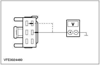
2 Measure voltage between fuse F33 (15 A) And "weight". |
|
|
• Does the battery voltage register? |
|
|
→ Yes |
|
|
Go to X5 |
|
|
→ No |
|
|
RESTORE power to fuse F33 using the wiring diagrams. Check the correct operation of the system. CHECK the CJB, if necessary INSTALL the new element. |
|
|
X5: CHECK POWER SUPPLY OF HAZARD LIGHT BUTTON |
|
|
1 Enter the OFF position. |
|
|
2 Disconnect the Hazard Light Button - C458. |
|
|
3 Drive the ON position. |
|
|
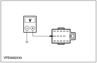
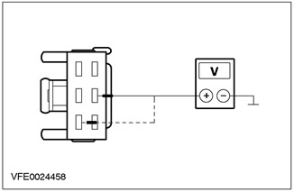
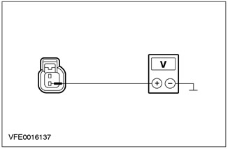
4 Measure the voltage between pin 13 C458 of the hazard warning light button, circuit 29-LG8 (orange), from the wiring side and "weight". |
|
• Does the battery voltage register? |
|
|
→ Yes |
|
|
Check the hazard warning light button If necessary, INSTALL a new item. Check the correct operation of the system. |
|
|
→ No |
|
|
RESTORE power to the hazard warning light button, circuit 29-LG8 (orange), using electrical diagrams. Check the correct operation of the system. If necessary, INSTALL a new CJB. |
|
|
X6: CHECK FUSE F59 |
|
|
1 Enter the OFF position. |
|
|
2 CHECK Fuse F59 (CJB). |
|
|
3 Check fuse F59 (7.5 A). |
|
|
• Fuse F59 (7.5 A) serviceable? |
|
|
→ Yes |
|
|
Go to X7 |
|
|
→ No |
|
|
Install new fuse F59 (7.5 A). If the fuse blows again, LOCATE and REPAIR the short circuit using the wiring diagrams. CHECK the system is working properly. |
|
|
X7: CHECK POWER SUPPLY OF F59 FUSE |
|
|
1 Connect Fuse F59 (CJB). |
|
|
2 Drive the ON position. |
|
|
3 Measure voltage between fuse F59 (7.5 A) And "weight". |
|
|
• Does the battery voltage register? |
|
|
→ Yes |
|
|
Go to X8 |
|
|
→ No |
|
|
RESTORE power to fuse F59 using the wiring diagrams. Check the correct operation of the system. CHECK the CJB, if necessary INSTALL the new element. |
|
|
X8: CHECK THE POWER SUPPLY OF THE TURN SIGNAL SWITCH |
|
|
1 Enter the OFF position. |
|
|
2 Disconnect Turn Signal Switch - C459. |
|
|
3 Drive the ON position. |
|
|
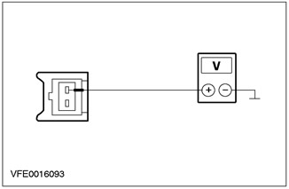
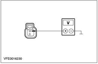
4 Measure the voltage between pin 2 C459 turn signal switch circuit 15-LG27 (green/black), from the wiring side and "weight". |
|
• Does the battery voltage register? |
|
|
→ Yes |
|
|
INSPECT the turn signal switch according to item check: Refer to Section 417-01 for more information. If necessary, INSTALL the new element. Check the correct operation of the system. |
|
|
→ No |
|
|
RESTORE power to turn signal switch circuit 15-LG27 (green/black), using electrical diagrams. Check the correct operation of the system. |
|
|
X9: CHECK TURN SIGNAL SWITCH |
|
|
1 Enter the OFF position. |
|
|
2 Disconnect Turn Signal Switch - C459. |
|
|
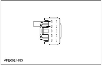
3 Connect the jumper wire to connector C459 of the turn signal switch between pin 2, circuit 15-LG27 (green/black), from the wiring side, and pin 1, electrical circuit 15S-LG1 (green/yellow), from the side of the electrical wiring. |
|
4 Drive the ON position. |
|
|
5 Check that the left turn signal bulbs are working properly. |
|
|
• Are the left turn signal lamps working properly? |
|
|
→ Yes |
|
|
INSPECT light switch according to element check: Refer to Section 417-01 for more information. If necessary, INSTALL the new element. Check the correct operation of the system. |
|
|
→ No |
|
|
Go to X10 |
|
|
X10: INSPECT LEFT TURN SIGNAL LAMP CONTROL CIRCUIT |
|
|
1 Enter the OFF position. |
|
|
2 Connect Turn Signal Switch - C459. |
|
|
3 Disconnect the Hazard Light Button - C458. |
|
|
4 Drive the ON position. |
|
|
5 Turn on the LEFT TURN SIGNAL. |
|
|
6 Measure the voltage between C458 pin 3 of the hazard warning light button, wiring side circuit and "weight". |
|
• Does the battery voltage register? |
|
|
→ Yes |
|
|
Go to X11 |
|
|
→ No |
|
|
REPAIR open circuit 15S-LG1 (green/yellow) between the turn signal switch and the hazard warning light button, using the wiring diagrams. Check the correct operation of the system. |
|
|
X11: CHECK HAZARD LIGHT BUTTON |
|
|
1 Connect the jumper wire to connector C458 of the hazard warning light button between pin 3, circuit 15S-LG1 (green/yellow), from the wiring side, and pin 12, electrical circuit 49S-LG3 (blue), from the side of the electrical wiring. |
|
2 Drive the ON position. |
|
|
3 Turn on the LEFT TURN SIGNAL. |
|
|
4 Check if the left turn signal lamps are on continuously. |
|
|
• Are the left turn signal lamps on continuously? |
|
|
→ Yes |
|
|
Check the hazard warning light button If necessary, INSTALL a new item. Check the correct operation of the system. |
|
|
→ No |
|
|
REPAIR open circuit 49S-LG3 (blue) between the hazard warning light button and connection S3, using the wiring diagrams. Check the correct operation of the system. |
|
|
X12: CHECK TURN SIGNAL SWITCH |
|
|
1 Enter the OFF position. |
|
|
2 Disconnect Turn Signal Switch - C459. |
|
|
3 Connect the jumper wire to connector C459 of the turn signal switch between pin 2, circuit 15-LG27 (green/black), from the wiring side, and pin 3, electrical circuit 15S-LG2 (green/blue), from the side of the electrical wiring. |
|
4 Drive the ON position. |
|
|
5 Check that the right turn signal bulbs are working properly. |
|
|
• Are the right turn signal lamps working properly? |
|
|
→ Yes |
|
|
INSPECT light switch according to element check: Refer to Section 417-01 for more information. If necessary, INSTALL the new element. Check the correct operation of the system. |
|
|
→ No |
|
|
Go to X13 |
|
|
X13: INSPECT RIGHT TURN SIGNAL LAMP CONTROL CIRCUIT |
|
|
1 Enter the OFF position. |
|
|
2 Connect Turn Signal Switch - C459. |
|
|
3 Disconnect the Hazard Light Button - C458. |
|
|
4 Drive the ON position. |
|
|
5 Turn on the RIGHT TURN SIGNAL. |
|
|
6 Measure the voltage between C458 pin 6 of the hazard warning light button, wiring side circuit and "weight". |
|
• Does the battery voltage register? |
|
|
→ Yes |
|
|
Go to X14 |
|
|
→ No |
|
|
REPAIR open circuit 15S-LG2 (green/blue) between the turn signal switch and the hazard warning light button, using the wiring diagrams. Check the correct operation of the system. |
|
|
X14: CHECK HAZARD LIGHT BUTTON |
|
|
1 Enter the OFF position. |
|
|
2 Connect the jumper wire to connector C458 of the hazard warning light button between pin 6, circuit 15S-LG2 (green/blue), from the wiring side, and pin 14, electrical circuit 49S-LG4 (blue/red), from the side of the electrical wiring. |
|
3 Drive the ON position. |
|
|
4 Turn on the RIGHT TURN SIGNAL. |
|
|
5 Check if the right turn signal lamps are on continuously. |
|
|
• Are the right turn signal lamps on continuously? |
|
|
→ Yes |
|
|
Check the hazard warning light button If necessary, INSTALL a new item. Check the correct operation of the system. |
|
|
→ No |
|
|
REPAIR open circuit 49S-LG4 (blue/red) between the hazard warning light button and connection S4, using the wiring diagrams. Check the correct operation of the system. |
|
|
X15: CHECK HAZARD LIGHT BUTTON |
|
|
1 Enter the OFF position. |
|
|
2 Disconnect the Hazard Light Button - C458. |
|
|
3 Drive the ON position. |
|
|
4 Check if the left turn signal lamps are on continuously. |
|
|
• Are all left turn signal lamps on continuously? |
|
|
→ Yes |
|
|
Go to X16 |
|
|
→ No |
|
|
Check the hazard warning light button If necessary, INSTALL a new item. Check the correct operation of the system. |
|
|
X16: CHECK INSTRUMENT PANEL |
|
|
1 Enter the OFF position. |
|
|
2 Disconnect Instrument panel - C809. |
|
|
3 Drive the ON position. |
|
|
4 Check if the left turn signal lamps are on continuously. |
|
|
• Are all left turn signal lamps on continuously? |
|
|
→ Yes |
|
|
REPAIR the short to power supply of the electrical circuits connected to the S3 connection using the wiring diagrams. Check the correct operation of the system. |
|
|
→ No |
|
|
CHECK instrument panel. If necessary, INSTALL the new element. Check the correct operation of the system. |
|
|
X17: CHECK HAZARD LIGHT BUTTON |
|
|
1 Enter the OFF position. |
|
|
2 Disconnect the Hazard Light Button - C458. |
|
|
3 Drive the ON position. |
|
|
4 Check if the right turn signal lamps are on continuously. |
|
|
• Are all right turn signal lamps on continuously? |
|
|
→ Yes |
|
|
Go to X18 |
|
|
→ No |
|
|
Check the hazard warning light button If necessary, INSTALL a new item. Check the correct operation of the system. |
|
|
X18: CHECK INSTRUMENT PANEL |
|
|
1 Enter the OFF position. |
|
|
2 Disconnect Instrument panel - C809. |
|
|
3 Drive the ON position. |
|
|
4 Check if the right turn signal lamps are on continuously. |
|
|
• Are all right turn signal lamps on continuously? |
|
|
→ Yes |
|
|
REPAIR the short to power supply of the circuits connected to the S4 connection using the wiring diagrams. Check the correct operation of the system. |
|
|
→ No |
|
|
CHECK instrument panel. If necessary, INSTALL the new element. Check the correct operation of the system. |
|
PINPOINT TEST Y: HAZARD LIGHTS DO NOT WORK/STEADY ON
|
STATES |
DETAILS/RESULTS/ACTIONS |
|
Y1: IDENTIFY THE STATE IN WHICH THE FAULT IS APPEARING. |
|
|
1 Operate the hazard warning light button. |
|
|
2 Check that the hazard warning lights are not working. |
|
|
• Are the hazard warning lights not working? |
|
|
→ Yes |
|
|
Go to Y2 |
|
|
→ No |
|
|
The hazard warning lights do not work when the anti-theft alarm is activated. Go to Y3 |
|
|
The hazard warning lights are permanently on: CHECK the hazard warning light button. If necessary, INSTALL the new element. Check the correct operation of the system. |
|
|
The hazard warning lights flash continuously without triggering the anti-theft alarm: CHECK the hazard warning light button. If necessary, INSTALL the new element. Check the correct operation of the system. |
|
|
The hazard warning lights flash continuously when the anti-theft alarm is triggered: Go to Y3 |
|
|
Y2: CHECK GROUND OF HAZARD LIGHT BUTTON |
|
|
1 Enter the OFF position. |
|
|
2 Disconnect the Hazard Light Button - C458. |
|
|
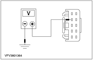
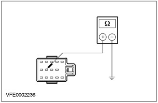
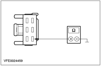
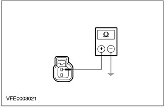
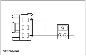
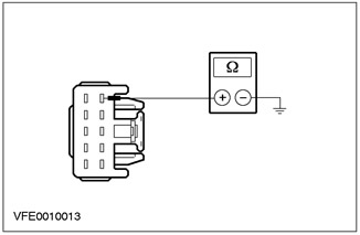
3 Measure the resistance between pin 10 C458 of the hazard warning light button, circuit 91-LG8 (black/orange), from the wiring side and "weight". |
|
• Is the resistance less than 2 ohms? |
|
|
→ Yes |
|
|
Check the hazard warning light button If necessary, INSTALL a new item. Check the correct operation of the system. |
|
|
→ No |
|
|
REPAIR open circuit 91-LG8 (black/orange) between the hazard warning light button and the S12 connection using the wiring diagrams. Check the correct operation of the system. |
|
|
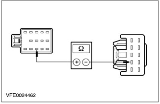
Y3: CHECK CONTROL CIRCUIT FROM THE ANTI-THEFT ALARM MODULE |
|
|
1 Enter the OFF position. |
|
|
2 Disconnect the Anti-Theft/Central Locking Module - C452. |
|
|
3 Disconnect the Hazard Light Button - C458. |
|
|
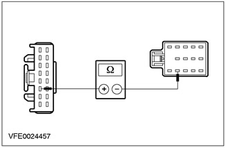
4 Measure the resistance between pin 6 C452 of the anti-theft/central locking module, circuit 31S-LG8 (black/orange), on the wiring side, and pin 5 C458 of the hazard warning light button, electrical circuit 31S-LG8 (black/orange), from the side of the electrical wiring. |
|
• Is the resistance less than 2 ohms? |
|
|
→ Yes |
|
|
Check the hazard warning light button If necessary, INSTALL a new item. Check the correct operation of the system. If the problem persists: Refer to Section 419-01A / 419-01B for more information. |
|
|
→ No |
|
|
REPAIR open circuit 31S-LG8 (black/orange) between the anti-theft/central locking module and the hazard warning light button, using the wiring diagrams. Check the correct operation of the system. |
|
PINPOINT TEST Z: ONE OR MORE OF THE TURN INDICATION/HAZARD LIGHTS DO NOT WORK.
|
STATES |
DETAILS/RESULTS/ACTIONS |
|
Z1: IDENTIFY WHEN TURN SIGNAL LAMP IS NOT WORKING |
|
|
1 Operate the hazard warning light button. |
|
|
2 Identify a broken lamp. |
|
|
• Is one of the left turn signal bulbs not working? |
|
|
→ Yes |
|
|
Side turn signal lamp, left side, not working: Go to Z2 |
|
|
Front turn signal lamp, left side, not working: Go to Z4 |
|
|
Rear turn signal lamp, left side, inoperative, 3-/5-door models only: Go to Z6 |
|
|
Rear turn signal lamp, left side, inoperative, 4-door models and models only "station wagon": Move to Z8 |
|
|
Left Turn Signal Warning Lamp Not Working: Refer to Section 413-01 for more information. |
|
|
Front lamp and side turn signal lamp, left side, not working: Go to Z18 |
|
|
→ No |
|
|
Side turn signal lamp, right side, not working: Go to Z10 |
|
|
Front turn signal lamp, right side, not working: Go to Z12 |
|
|
Rear turn signal lamp, right side, inoperative, 3-/5-door models only: Go to Z14 |
|
|
Rear turn signal lamp, right side, inoperative, 4-door models and models only "station wagon": Move to Z16 |
|
|
Right Turn Signal Warning Lamp Not Working: Refer to Section 413-01 for more information. |
|
|
Z2: CHECK POWER SUPPLY TO SIDE TURN SIGNAL LAMP, LEFT |
|
|
1 Disconnect Side turn signal lamp, left side - C753. |
|
|
2 Activate the ALARM LIGHTS. |
|

|
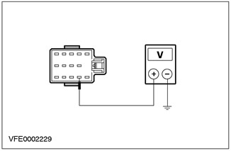
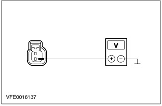
3 Measure the voltage between pin 2 C753 side turn signal lamp, left side, circuit 49S-LG13 (blue/red), from the wiring side and "weight". |
|
• Is battery variable voltage being registered? |
|
|
→ Yes |
|
|
Go to Z3 |
|
|
→ No |
|
|
REPAIR open circuit 49S-LG13 (blue/red) between connection S104 and side turn signal lamp, left side, using the wiring diagrams. Check the correct operation of the system. |
|
|
Z3: CHECK SIDE TURN SIGNAL LAMP GROUND. LEFT SIDE |
|

|
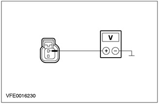
1 Measure the resistance between pin 1 C753 side turn signal lamp, left side, circuit 31-LG13 (black), from the wiring side and "weight". |
|
• Is the resistance less than 2 ohms? |
|
|
→ Yes |
|
|
CHECK side turn signal lamp, left side. If necessary, INSTALL the new element. CHECK the system is working properly. |
|
|
→ No |
|
|
REPAIR open circuit 31-LG13 (black) between side turn signal lamp, left side, and connection S121, using the wiring diagrams. Check the correct operation of the system. |
|
|
Z4: CHECK POWER SUPPLY OF FRONT TURN SIGNAL LAMP, LEFT SIDE |
|
|
1 Disconnect Turn signal lamp, left side, front - C713. |
|
|
2 Activate the ALARM LIGHTS. |
|
|
3 Measure the voltage between pin 2 C713 front turn signal lamp, left side, circuit 49S-LG11 (blue/orange), from the wiring side and "weight". |
|
• Is battery variable voltage being registered? |
|
|
→ Yes |
|
|
Go to Z5 |
|
|
→ No |
|
|
REPAIR open circuit 49S-LG11 (blue/orange) between connection S104 and front turn signal lamp, left side, using the wiring diagrams. Check the correct operation of the system. |
|
|
Z5: CHECK GROUND OF FRONT TURN SIGNAL LAMP, LEFT SIDE |
|

|
1 Measure the resistance between pin 1 C713 front turn signal lamp, left side, circuit 31-LG11 (black), from the wiring side and "weight". |
|
• Is the resistance less than 2 ohms? |
|
|
→ Yes |
|
|
CHECK turn signal lamp, left side. If necessary, INSTALL the new element. Check the correct operation of the system. |
|
|
→ No |
|
|
REPAIR open circuit 31-LG11 (black) between front turn signal lamp, left side, and connection S121, using the wiring diagrams. Check the correct operation of the system. |
|
|
Z6: CHECK REAR TURN SIGNAL LAMP POWER LEFT |
|
|
1 Enter the OFF position. |
|
|
2 Disconnect Turn signal lamp, left side, rear - C461. |
|
|
3 Drive the ON position. |
|
|
4 Activate the ALARM LIGHTS. |
|
|
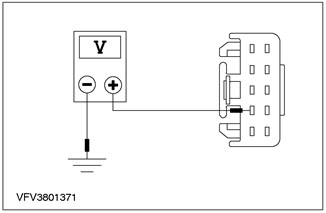
5 Measure the voltage between C461 rear turn signal lamp pin 1, left side, circuit 49S-LG12 (blue), from the wiring side and "weight". |
|
• Is battery variable voltage being registered? |
|
|
→ Yes |
|
|
Go to Z7 |
|
|
→ No |
|
|
REPAIR the gap (s) connections between connection S3 and rear turn signal lamp, left side, using the wiring diagrams. Check the correct operation of the system. |
|
|
Z7: CHECK REAR TURN SIGNAL LAMP GROUND, LEFT |
|

|
1 Measure the resistance between C461 rear turn signal lamp pin 2, left side, circuit 31-LG12 (black), from the wiring side and "weight". |
|
• Is the resistance less than 2 ohms? |
|
|
→ Yes |
|
|
CHECK rear turn signal lamp, left side. If necessary, INSTALL the new element. Check the correct operation of the system. |
|
|
→ No |
|
|
REPAIR the gap (s) connections between rear turn signal lamp, left side, and connection S184, using the wiring diagrams. Check the correct operation of the system. |
|
|
Z8: CHECK REAR LIGHT UNIT POWER, LEFT |
|
|
1 Disconnect Light unit, left side, rear - C476 (only 4-door variant) / C474 (only "station wagon"). |
|
|
2 Activate the ALARM LIGHTS. |
|
|
3 Measure the voltage between the rear light unit, left side: - 4-door version only: pin 3 C476, electrical circuit 49S-LG12 (blue), from the wiring side and "weight". - only "station wagon": pin 5 C474, electric circuit 49S-LG12 (blue), from the wiring side and "weight". |
|
• Is battery variable voltage being registered? |
|
|
→ Yes |
|
|
Go to Z9 |
|
|
→ No |
|
|
REPAIR the gap (s) connections between connection S3 and rear light unit, left side, using the wiring diagrams. Check the correct operation of the system. |
|
|
Z9: CHECK REAR LIGHT UNIT GROUND, LEFT |
|
|
1 Measure the resistance between the rear light unit, left side: - 4-door version only: pin 6 C476, electrical circuit 31-LF23 (black), from the wiring side and "weight". - only "station wagon": pin 6 C474, electric circuit 31-LF23A (black), from the wiring side and "weight". |
|
• Is the resistance less than 2 ohms? |
|
|
→ Yes |
|
|
CHECK rear turn signal lamp, left side. If necessary, INSTALL the new element. Check the correct operation of the system. |
|
|
→ No |
|
|
REPAIR the gap (s) circuits between rear turn signal lamp, left side, and "weight", using electrical diagrams. Check the correct operation of the system. |
|
|
Z10: CHECK POWER SUPPLY OF FRONT SIDE TURN SIGNAL LAMP, RIGHT SIDE |
|
|
1 Disconnect Side turn signal lamp, right side - C754. |
|
|
2 Activate the ALARM LIGHTS. |
|
|
3 Measure the voltage between pin 2 C754 front side turn signal lamp, right side, circuit 49S-LG20 (blue/white), from the wiring side and "weight". |
|
• Is battery variable voltage being registered? |
|
|
→ Yes |
|
|
Go to Z11 |
|
|
→ No |
|
|
REPAIR the gap (s) connections between connection S4 and front side turn signal lamp, right side, using the wiring diagrams. Check the correct operation of the system. |
|
|
Z11: CHECK GROUND OF SIDE TURN SIGNAL LAMP, RIGHT SIDE |
|
|
1 Measure the resistance between pin 1 C754 side turn signal lamp, right side, circuit 31-LG20 (black), from the wiring side and "weight". |
|
• Is the resistance less than 2 ohms? |
|
|
→ Yes |
|
|
CHECK side turn signal lamp, right side. If necessary, INSTALL the new element. CHECK the system is working properly. |
|
|
→ No |
|
|
REPAIR open circuit 31-LG20 (black) between front side turn signal lamp, right side, and connection S52, using the wiring diagrams. CHECK the system is working properly. |
|
|
Z12: CHECK POWER SUPPLY OF FRONT TURN SIGNAL LAMP, RIGHT SIDE |
|
|
1 Disconnect Front turn signal lamp, right side - C714. |
|
|
2 Activate the ALARM LIGHTS. |
|
|
3 Measure the voltage between pin 2 C714 front turn signal lamp, right side, circuit 49S-LG18 (blue), from the wiring side and "weight". |
|
• Is battery variable voltage being registered? |
|
|
→ Yes |
|
|
Go to Z13 |
|
|
→ No |
|
|
REPAIR open circuit 49S-LG18 (blue) between connection S4 and front turn signal lamp, right side, using the wiring diagrams. CHECK the system is working properly. |
|
|
Z13: CHECK GROUND OF FRONT TURN SIGNAL LAMP RIGHT SIDE |
|
|
1 Measure the resistance between pin 1 C714 front turn signal lamp, right side, circuit 31-LG18 (black), from the wiring side and "weight". |
|
• Is the resistance less than 2 ohms? |
|
|
→ Yes |
|
|
CHECK turn signal lamp, right side. If necessary, INSTALL the new element. CHECK the system is working properly. |
|
|
→ No |
|
|
REPAIR open circuit 31-LG18 (black) between front turn signal lamp, right side, and connection S109, using the wiring diagrams. CHECK the system is working properly. |
|
|
Z14: CHECK POWER SUPPLY TO REAR TURN SIGNAL LAMP, RIGHT SIDE |
|
|
1 Disconnect Rear turn signal lamp, right side - C462. |
|
|
2 Activate the ALARM LIGHTS. |
|
|
3 Measure the voltage between pin 1 C462 rear turn signal lamp, right side, circuit 49S-LG19 (blue/red), from the wiring side and "weight". |
|
• Is battery variable voltage being registered? |
|
|
→ Yes |
|
|
Go to Z15 |
|
|
→ No |
|
|
REPAIR open circuit 49S-LG19 (blue/red) between connection S4 and rear turn signal lamp, right side, using the wiring diagrams. CHECK the system is working properly. |
|
|
Z15: CHECK REAR TURN SIGNAL LAMP GROUND, RIGHT SIDE |
|
|
1 Measure the resistance between C462, rear turn signal lamp pin 2, right side, circuit 31-LG19 (black), from the wiring side and "weight". |
|
• Is the resistance less than 2 ohms? |
|
|
→ Yes |
|
|
CHECK rear turn signal lamp, right side. If necessary, INSTALL the new element. CHECK the system is working properly. |
|
|
→ No |
|
|
REPAIR the gap (s) circuits between rear turn signal lamp, right side, and "weight", using electrical diagrams. CHECK the system is working properly. |
|
|
Z16: CHECK THE POWER SUPPLY OF THE REAR LIGHT UNIT, RIGHT SIDE |
|
|
1 Disconnect Light unit, right side, rear - C477 (only 4-door variant) / C477 (only "station wagon"). |
|
|
2 Activate the ALARM LIGHTS. |
|
|
3 Measure the voltage between the rear light unit, right side: - 4-door version only: pin 1 C477, electrical circuit 49S-LG19 (blue/red), from the wiring side and "weight". - only "station wagon": pin 5 C475, electrical circuit 49S-LG19 (blue/red), from the wiring side and "weight". |
|
• Is battery variable voltage being registered? |
|
|
→ Yes |
|
|
Go to Z17 |
|
|
→ No |
|
|
REPAIR open circuit 49S-LG19 (blue/red) between connection S4 and rear light unit, right side, using the wiring diagrams. CHECK the system is working properly |
|
|
Z17: CHECK REAR LIGHT UNIT GROUND |
|
|
1 Measure the resistance between the rear light unit, right side: - 4-door version only: pin 4 C477, electrical circuit 31-LF24 (black), from the wiring side and "weight". - only "station wagon": pin 6 C475, electrical circuit 31-LF24A (black), from the wiring side and "weight". |
|
• Is the resistance less than 2 ohms? |
|
|
→ Yes |
|
|
CHECK rear turn signal lamp, right side. If necessary, INSTALL the new element. CHECK the system is working properly. |
|
|
→ No |
|
|
REPAIR open circuit 31-LF24 (A) (black) between rear turn signal lamp, right side, and "weight", using electrical diagrams. CHECK the system is working properly. |
|
|
Z18: CHECK POWER SUPPLY OF LEFT TURN SIGNAL LAMP, FRONT |
|
|
1 Disconnect Left turn signal bulb, front - C713. |
|
|
2 Engage the LEFT TURN SIGNAL. |
|

|
3 Measure the voltage between C713 pin 2, left turn signal front lamp, circuit 49S-LG11 (blue/orange), from the wiring side and "weight". |
|
• AC voltage registered? |
|
|
→ Yes |
|
|
REPAIR open circuit 31-LG11 (black) between connection S121 and "weight", using electrical diagrams. CHECK the system is working properly. |
|
|
→ No |
|
|
RESTORE power to circuit 49S-LG11 (blue/orange) between the front left turn signal lamp and connection S104, using the wiring diagrams. CHECK the system is working properly. |
|
PINPOINT TEST AA: TURN INDICATOR LAMPS WORK PROPERLY BUT NO BEEP
|
STATES |
DETAILS/RESULTS/ACTIONS |
|
AA1: CHECK TURN SIGNAL SWITCH GROUND |
|
|
1 Enter the OFF position. |
|
|
2 Disconnect Turn Signal Switch - C459. |
|
|
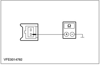
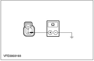
3 Measure the resistance between pin 5 C459 turn signal switch, circuit 91-LG43 (black/white), from the wiring side and "weight". |
|
• Is the resistance less than 2 ohms? |
|
|
→ Yes |
|
|
Go to AA2 |
|
|
→ No |
|
|
REPAIR open circuit 91-LG43 (black/white) between the turn signal switch and connection S12 using the wiring diagrams. If necessary, INSTALL a new turn signal switch. CHECK the system is working properly. |
|
|
AA2: CHECK TURN SIGNAL SWITCH |
|
|
1 Activate the ALARM LIGHTS. |
|
|
2 Measure the voltage between pin 4 C459 turn signal switch circuit 29S-LG43 (orange/white), from the wiring side and "weight". |
|
• Is battery variable voltage being registered? |
|
|
→ Yes |
|
|
INSPECT the turn signal switch according to item check: Refer to Section 417-01 for more information. If necessary, INSTALL the new element. CHECK the system is working properly. |
|
|
→ No |
|
|
Go to AA3 |
|
|
AA3: INSPECT HORN CONTROL CIRCUIT FROM HAZARD LIGHT BUTTON |
|
|
1 Disconnect the Hazard Light Button - C458. |
|
|
2 Measure the resistance between pin 4 C459 turn signal switch circuit 29S-LG43 (orange/white), on the wiring side, and pin 8 C458 of the hazard warning light button, electrical circuit 29S-LG43 (orange/white), from the side of the electrical wiring. |
|
• Is the resistance less than 2 ohms? |
|
|
→ Yes |
|
|
Check the hazard warning light button If necessary, INSTALL a new item. CHECK the system is working properly. |
|
|
→ No |
|
|
REPAIR open circuit 29S-LG43 (orange/white) between the turn signal switch and the hazard warning light button, using the wiring diagrams. CHECK the system is working properly. |
|
Visitor comments