|
STATES |
DETAILS/RESULTS/ACTIONS |
|
AQ1: FUSE CHECK F44 (CJB) |
|
|
1 Enter the OFF position. |
|
|
2 CHECK Fuse F44 (CJB). |
|
|
3 Check fuse F44 (20 A) |
|
|
• Is the fuse good? |
|
|
→ Yes |
|
|
Go to AQ2 |
|
|
→ No |
|
|
INSTALL a new fuse F44 (20 A) and CHECK the system is working properly. If the fuse blows again, LOCATE and REPAIR the short circuit using the wiring diagrams. Check the correct operation of the system. |
|
|
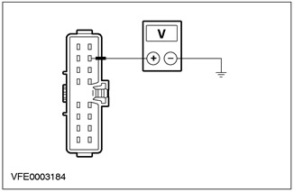
AQ2: CHECK THE VOLTAGE IN THE FUSE CIRCUIT F44 (CJB) |
|
|
1 Connect Fuse F44 (CJB). |
|
|
2 Drive the ON position. |
|
|
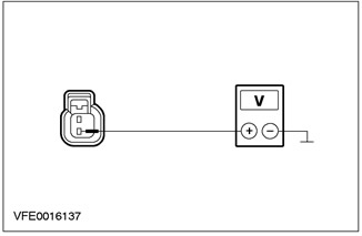
3 Measure the voltage between F44 (CJB) And "weight". |
|
|
• Does the battery voltage register? |
|
|
→ Yes |
|
|
Go to AQ3 |
|
|
→ No |
|
|
Using the wiring diagrams, LOCATE and REPAIR the short circuit in the power circuit of fuse F44. If necessary, INSTALL a new CJB. Check the correct operation of the system. |
|
|
AQ3: LIGHT SWITCH ELECTRICAL POWER CIRCUIT CHECK |
|
|
1 Enter the OFF position. |
|
|
2 Disconnect the C320 light switch. |
|
|
3 Drive the ON position. |
|
|
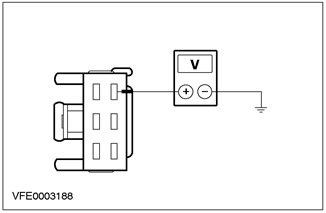
4 Measure the voltage between pin 7 of connector C320, light switch, circuit 15-LD16 (red-green), from the wiring side, and "weight". |
|
• Does the battery voltage register? |
|
|
→ Yes |
|
|
CHECK the light switch as described in chap. "Checking the elements", attached to the wiring diagrams, INSTALL a new one if necessary. Check the correct operation of the system. |
|
|
→ No |
|
|
LOCATE and REPAIR open circuit 15-LD16 using the wiring diagrams (red-green) between the fuse and the light switch. Check the correct operation of the system. |
|
PINPOINT AR TEST: FRONT FOG LIGHTS DO NOT WORK
|
STATES |
DETAILS/RESULTS/ACTIONS |
|
AR1: CHECK THE FRONT FOG LIGHTS |
|
|
1 Drive the ON position. |
|
|
2Turn on the front fog lights. |
|
|
3 Check the operation of the front fog lamps. |
|
|
• Is the front fog lamp on? |
|
|
→ Yes |
|
|
Go to AR2 |
|
|
→ No |
|
|
INSTALL a new light switch. Check the correct operation of the system. |
|
|
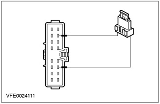
AR2: LIGHT SWITCH TEST |
|
|
1 Enter the OFF position. |
|
|
2 Disconnect the C320 light switch. |
|
|
3 Install fusible jumper wire (20 A) into connector C320 of the light switch, between pin 7, circuit 15-LD16 (red-green), from the wiring side, and pin 3, electrical circuit 15S-LD1 (yellow-green), from the side of the electrical wiring. |
|
4 Drive the ON position. |
|
|
5Check the front fog lights. |
|
|
• Are the front fog lights on? |
|
|
→ Yes |
|
|
INSTALL a new light switch. Check the correct operation of the system. |
|
|
→ No |
|
|
LOCATE and REPAIR open circuit 15S-LD1 using the wiring diagrams (yellow-green) between light switch and splice S110. Check the correct operation of the system. |
|
PINPOINT TEST AS: REAR FOG LIGHTS DO NOT WORK
|
STATES |
DETAILS/RESULTS/ACTIONS |
|
AS1: CHECK THE REAR FOG LIGHTS |
|
|
1 Drive the ON position. |
|
|
2 Turn on the REAR FOG LIGHTS. |
|
|
3Check the rear fog lights. |
|
|
• Are the rear fog lights on? |
|
|
→ Yes |
|
|
4-door only: Go to AS2 |
|
|
All others: Go to AS3 |
|
|
→ No |
|
|
INSTALL a new light switch. Check the correct operation of the system. |
|
|
AS2: TEST LIGHT ASSEMBLY GROUND ELECTRICAL |
|
|
1 Enter the OFF position. |
|
|
2 Turn on the SIDE LIGHTS. |
|
|
3 Check the parking lights. |
|
|
• Are the marker lights on? |
|
|
→ Yes |
|
|
Go to AS3 |
|
|
→ No |
|
|
LOCATE and REPAIR open circuit 31-DA18 using the wiring diagrams (black) between splice S184 and earth point G46. Check the correct operation of the system. |
|
|
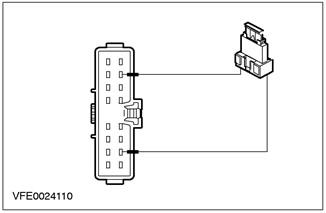
AS3: CHECK LIGHT SWITCH |
|
|
1 Disconnect the C320 light switch. |
|
|
2 Install fusible jumper wire (20 A) into connector C320 of the light switch between pin 7, circuit 15-LD16 (red-green), and pin 2, electrical circuit 15S-LD6 (yellow-green), from the side of the electrical wiring. |
|
3 Drive the ON position. |
|
|
4Check the rear fog lights. |
|
|
• Are the rear fog lights on? |
|
|
→ Yes |
|
|
INSTALL a new light switch. Check the correct operation of the system. |
|
|
→ No |
|
|
4-Door, Right Hand Drive Only: Using the wiring diagrams, LOCATE and REPAIR open circuit 15S-LD6 (yellow-green) or 15S-LG9 (black and green) between light switch and splice S210. Check the correct operation of the system. |
|
|
Go to AT1 |
|
PINPOINT TEST AT: SEPARATE (IE) ANTI-FOG HEADLIGHT (S) /FLASHLIGHT (AND) DOES NOT WORK (UT)
|
STATES |
DETAILS/RESULTS/ACTIONS |
|
AT1: DETERMINING THE STATE IN WHICH THE FAULT IS APPEARING |
|
|
1 Drive the ON position. |
|
|
2 Turn on the FOG LIGHTS/LIGHTS. |
|
|
3Check the front fog lights. |
|
|
• Is one of the front fog lights not working? |
|
|
→ Yes |
|
|
Front fog lamp, left side: Go to AT2 |
|
|
Front fog lamp, right side: Go to AT3 |
|
|
→ No |
|
|
Rear fog light not working (right hand drive option "station wagon"): Move to AT4 |
|
|
Rear fog light not working (right hand drive option "station wagon"): Go to AT5 |
|
|
Rear fog light not working (4-door variant): Go to AT6 |
|
|
Rear fog light not working (left-hand drive version, 3/5-door version): Go to AT9 |
|
|
Rear fog light not working (right-hand drive version, 3/5-version): Go to AT10 |
|
|
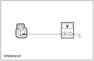
AT2: FOG LAMP POWER CIRCUIT CHECK LEFT |
|
|
1 Enter the OFF position. |
|
|
2 Disconnect C302 left front fog lamp. |
|
|
3 Drive the ON position. |
|
|
4Turn on the front fog lights. |
|
|
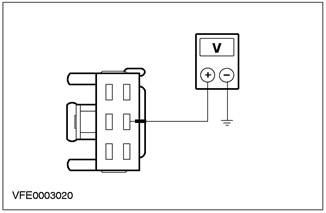
5 Measure the voltage between pin 2 of connector C302 of left front fog lamp circuit 15S-LD11 (white-green), from the wiring side, and "weight". |
|
• Does the battery voltage register? |
|
|
→ Yes |
|
|
LOCATE and REPAIR open circuit 31-LD11 using the wiring diagrams (black) and 31-DA3 (black) between the front fog lamp and earth point G37. INSTALL a new fog lamp if necessary. Check the correct operation of the system. |
|
|
→ No |
|
|
LOCATE and REPAIR open circuit 15S-LD11 using the wiring diagrams (white-green) between splice S110 and front fog lamp. INSTALL a new fog lamp if necessary. Check the correct operation of the system. |
|
|
AT3: RIGHT FOG LIGHT ELECTRICAL POWER CIRCUIT TEST |
|
|
1 Enter the OFF position. |
|
|
2 Disconnect C304 right front fog lamp. |
|
|
3 Drive the ON position. |
|
|
4Turn on the front fog lights. |
|
|
5 Measure the voltage between pin 2 of connector C304 of the right front fog lamp circuit 15S-LD17 (white-green), from the wiring side, and "weight". |
|
• Does the battery voltage register? |
|
|
→ Yes |
|
|
LOCATE and REPAIR open circuit 31-LD17 using the wiring diagrams (black) and 31-DA4 (black) between the front fog lamp and earth point G56. INSTALL a new fog lamp if necessary. Check the correct operation of the system. |
|
|
→ No |
|
|
LOCATE and REPAIR open circuit 15S-LD17 using the wiring diagrams (white-green) between splice S110 and front fog lamp. INSTALL a new fog lamp if necessary. Check the correct operation of the system. |
|
|
AT4: LEFT REAR LIGHT ASSEMBLY ELECTRICAL INSPECTION |
|
|
1 Enter the OFF position. |
|
|
2 Disconnect the C474 left rear light assembly. |
|
|
3 Drive the ON position. |
|
|
4 Turn on the REAR FOG LIGHTS. |
|

|
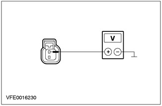
5 Measure the voltage between pin 4 of connector C474, left tail light assembly, circuit 15S-LD6 (yellow-green), from the wiring side, and "weight". |
|
• Does the battery voltage register? |
|
|
→ Yes |
|
|
Using the wiring diagrams, LOCATE and REPAIR open circuit 31-LF23A (black) and 31-DA18 (black) between the rear light assembly and "weight". INSTALL a new tail light assembly if necessary. Check the correct operation of the system. |
|
|
→ No |
|
|
LOCATE and REPAIR open circuit 15S-LD6 using the wiring diagrams (yellow-green) between light switch and tail light assembly. INSTALL a new tail light assembly if necessary. Check the correct operation of the system. |
|
|
AT5: RIGHT TAIL LIGHT ASSEMBLY ELECTRICAL CHECK |
|
|
1 Enter the OFF position. |
|
|
2 Disconnect the C475 right tail light assembly. |
|
|
3 Drive the ON position. |
|
|
4 Turn on the REAR FOG LIGHTS. |
|
|
5 Measure the voltage between pin 4 of connector C475, right tail light assembly, circuit 15S-LG9 (black and green), from the wiring side, and "weight". |
|
• Does the battery voltage register? |
|
|
→ Yes |
|
|
LOCATE and REPAIR open circuit 31-LF24A using the wiring diagrams (black) and 31-DA18 (black) between the rear light assembly and "weight". INSTALL a new tail light assembly if necessary. Check the correct operation of the system. |
|
|
→ No |
|
|
LOCATE and REPAIR open circuit 15S-LD6 using the wiring diagrams (yellow-green) and 15S-LG9 (black and green) between light switch and tail light assembly. INSTALL a new tail light assembly if necessary. Check the correct operation of the system. |
|
|
AT6: DETERMINING THE STATE IN WHICH THE FAULT IS APPEARING |
|
|
1 Identify a broken rear fog light. |
|
|
• Left rear fog light not working? |
|
|
→ Yes |
|
|
Go to AT7 |
|
|
→ No |
|
|
Go to AT8 |
|
|
AT7: LEFT REAR LIGHT ASSEMBLY ELECTRICAL INSPECTION |
|
|
1 Enter the OFF position. |
|
|
2 Disconnect the C476 left rear light assembly. |
|
|
3 Drive the ON position. |
|
|
4 Turn on the REAR FOG LIGHTS. |
|
|
5 Measure the voltage between pin 5 of connector C476, left tail light assembly, circuit 15S-LD6A (yellow-green), from the wiring side, and "weight". |
|
• Does the battery voltage register? |
|
|
→ Yes |
|
|
Using the wiring diagrams, LOCATE and REPAIR open circuit 31-LF23 (black) between tail light assembly and splice S184. INSTALL a new tail light assembly if necessary. Check the correct operation of the system. |
|
|
→ No |
|
|
LOCATE and REPAIR open circuit 15S-LD6A using the wiring diagrams (yellow-green) between splice S210 and rear light assembly. INSTALL a new tail light assembly if necessary. Check the correct operation of the system. |
|
|
AT8: RIGHT TAIL LIGHT ASSEMBLY ELECTRICAL CHECK |
|
|
1 Enter the OFF position. |
|
|
2 Disconnect the C477 right tail light assembly. |
|
|
3 Drive the ON position. |
|
|
4 Turn on the REAR FOG LIGHTS. |
|

|
5 Measure the voltage between pin 5 of connector C477, right tail light assembly, circuit 15S-LD12 (yellow-green), from the wiring side, and "weight". |
|
• Does the battery voltage register? |
|
|
→ Yes |
|
|
LOCATE and REPAIR open circuit 31-LF24 using the wiring diagrams (black) between tail light assembly and splice S184. INSTALL a new tail light assembly if necessary. Check the correct operation of the system. |
|
|
→ No |
|
|
LOCATE and REPAIR open circuit 15S-LD12 using the wiring diagrams (yellow-green) between splice S210 and rear light assembly. INSTALL a new tail light assembly if necessary. Check the correct operation of the system. |
|
|
AT9: REAR FOG LIGHT ELECTRICAL INSPECTION |
|
|
1 Enter the OFF position. |
|
|
2 Disconnect C434 left rear fog light. |
|
|
3 Drive the ON position. |
|
|
4 Turn on the REAR FOG LIGHTS. |
|
|
5 Measure the voltage between pin 1 of connector C434, left rear fog light circuit 15S-LD6 (yellow-green), from the wiring side, and "weight". |
|
• Does the battery voltage register? |
|
|
→ Yes |
|
|
LOCATE and REPAIR open circuit 31-LD6 using the wiring diagrams (black) and 31-DA18 (black) between the rear fog lamp and earth point G46. INSTALL a new rear fog light if necessary. Check the correct operation of the system. |
|
|
→ No |
|
|
LOCATE and REPAIR open circuit 15S-LD6 using the wiring diagrams (yellow-green) between the light switch and the rear fog lamp. INSTALL a new rear fog light if necessary. Check the correct operation of the system. |
|
|
AT10: RIGHT TAIL LIGHT ASSEMBLY ELECTRICAL CHECK |
|
|
1 Enter the OFF position. |
|
|
2 Disconnect the C430 right rear fog light. |
|
|
3 Drive the ON position. |
|
|
4 Turn on the REAR FOG LIGHTS. |
|

|
5 Measure the voltage between pin 1 of connector C430, right tail light assembly, circuit 15S-LG9 (black and green), from the wiring side, and "weight". |
|
• Does the battery voltage register? |
|
|
→ Yes |
|
|
LOCATE and REPAIR open circuit 31-LG9 using the wiring diagrams (black) and 31-DA18 (black) between the rear fog lamp and earth point G46. INSTALL a new tail light assembly if necessary. Check the correct operation of the system. |
|
|
→ No |
|
|
LOCATE and REPAIR open circuit 15S-LD6 using the wiring diagrams (yellow-green) and 15S-LG9 (black and green) between the light switch and the rear fog lamp. INSTALL a new tail light assembly if necessary. Check the correct operation of the system. |
|
PINPOINT TEST AU: FRONT FOG LIGHTS ON PERMANENTLY
|
STATES |
DETAILS/RESULTS/ACTIONS |
|
AU1: LIGHT SWITCH TEST |
|
|
1 Enter the OFF position. |
|
|
2 Disconnect the C320 light switch. |
|
|
3 Drive the ON position. |
|
|
4Check the front fog lights. |
|
|
• Are the front fog lights on? |
|
|
→ Yes |
|
|
Using the wiring diagrams, LOCATE and REPAIR short to power on circuits connected to splice S110. Check the correct operation of the system. |
|
|
→ No |
|
|
INSTALL a new light switch. Check the correct operation of the system. |
|
PINPOINT TEST AV: REAR FOG LIGHTS PERMANENTLY ON
|
STATES |
DETAILS/RESULTS/ACTIONS |
|
AV1: LIGHT SWITCH TEST |
|
|
1 Enter the OFF position. |
|
|
2 Disconnect the C320 light switch. |
|
|
3 Drive the ON position. |
|
|
4Check the rear fog lights. |
|
|
• Are the rear fog lights on? |
|
|
→ Yes |
|
|
Using the wiring diagrams, LOCATE and REPAIR for a short to power in the circuits connected to light switch connector C320 pin 2. Check the correct operation of the system. |
|
|
→ No |
|
|
INSTALL a new light switch. Check the correct operation of the system. |
|
Visitor comments