|
STATES |
DETAILS/RESULTS/ACTIONS |
|
AI1: DETERMINATION OF THE STATUS IN WHICH THE FAULT IS APPEARING. |
|
|
1 Turn on the SIDE LIGHTS. |
|
|
2Check side lights, taillights and license plate lights |
|
|
• Right side light (And) So the license plate light doesn't work? |
|
|
→ Yes |
|
|
Position light and tail light: Go to AI2 |
|
|
Marker light: Go to AI4 |
|
|
Rear light: Go to AI8 |
|
|
Both rear lights: Using the wiring diagrams, REPAIR open circuit 31-DA18 (black), between splice S184 (grounding point G46) and earth point G46. Check the correct operation of the system. |
|
|
License Plate Lamp: Go to AI16 |
|
|
Both license plate lamps: Go to AI19 |
|
|
All position lights, tail lights and license plate lights not working: Go to AI22 |
|
|
→ No |
|
|
Side lights and tail lights OK with side lights on, but not working with parking lights on: Go to AI25 |
|
|
Position light and tail light, left side: Go to AI3 |
|
|
Marker light, left side: Go to AI6 |
|
|
Rear light, left side: Go to AI12 |
|
|
License plate lamp, left side: Go to AI18 |
|
|
AI2: FUSE CHECK F57 (CJB) |
|
|
1 Enter the OFF position. |
|
|
2 CHECK Fuse F57 (CJB). |
|
|
3 Check fuse F57 (7.5 A) |
|
|
• Is the fuse good? |
|
|
→ Yes |
|
|
Go to AI3 |
|
|
→ No |
|
|
INSTALL a new fuse F57 (7.5 A) and TEST the system. If the fuse blows again, LOCATE and REPAIR the short circuit using the wiring diagrams. Check the correct operation of the system. |
|
|
AI3: CHECK FUSE F58 (CJB) |
|
|
1 Enter the OFF position. |
|
|
2CHECK Fuse F58 (CJB). |
|
|
3 Check fuse F58 (7.5 A) |
|
|
• Is the fuse good? |
|
|
→ Yes |
|
|
CHECK the CJB, INSTALL a new one if necessary. Check the correct operation of the system. |
|
|
→ No |
|
|
INSTALL a new fuse F58 (7.5 A) and TEST the system. If the fuse blows again, LOCATE and REPAIR the short circuit using the wiring diagrams. Check the correct operation of the system. |
|
|
AI4: RIGHT HEADLIGHT GROUND CIRCUIT CHECK |
|
|
1 Drive the ON position. |
|
|
2 Turn on the right TURN SIGNAL. |
|
|
3 Check the front turn signal. |
|
|
• Does the turn signal work correctly? |
|
|
→ Yes |
|
|
Go to AI5 |
|
|
→ No |
|
|
REPAIR open circuit 31-LE30 using the wiring diagrams (black) between headlight and splice S109 (earth point G56). Check the correct operation of the system. |
|
|
AI5: VOLTAGE CHECK IN THE ELECTRICAL CIRCUIT OF THE RIGHT HEADLIGHT |
|
|
1 Enter the OFF position. |
|
|
2 Disconnect the C837 right headlight. |
|
|
3 Turn on the SIDE LIGHTS. |
|
|
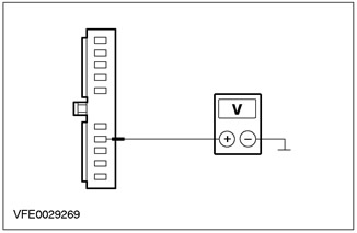
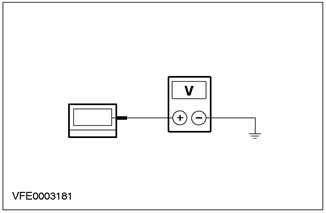
4 Measure the voltage between pin 4 of connector C837 of the right headlight, circuit 29S-LF16 (orange green), from the wiring side, and "weight". |
|
• Does the battery voltage register? |
|
|
→ Yes |
|
|
CHECK the headlight, INSTALL a new one if necessary. Check the correct operation of the system. |
|
|
→ No |
|
|
REPAIR open circuit 29S-LF16 using the wiring diagrams (orange green) between CJB and right headlight. Check the correct operation of the system. |
|
|
AI6: LEFT HEADLIGHT GROUND CIRCUIT CHECK |
|
|
1 Drive the ON position. |
|
|
2 Turn on the left TURN SIGNAL. |
|
|
3 Check the front turn signal. |
|
|
• Does the turn signal work correctly? |
|
|
→ Yes |
|
|
Go to AI7 |
|
|
→ No |
|
|
REPAIR open circuit 31-LE31 using the wiring diagrams (black) between headlight and splice S121 (earthing point G37). Check the correct operation of the system. |
|
|
AI7: VOLTAGE CHECK IN THE ELECTRICAL CIRCUIT OF THE LEFT HEADLIGHT |
|
|
1 Enter the OFF position. |
|
|
2 Disconnect the left headlight C836. |
|
|
3 Turn on the SIDE LIGHTS. |
|

|
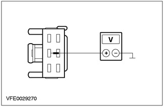
4 Measure the voltage between pin 4 of connector C836, left headlight, circuit 29S-LF7 (orange-blue), from the wiring side, and "weight". |
|
• Does the battery voltage register? |
|
|
→ Yes |
|
|
CHECK the headlight, INSTALL a new one if necessary. Check the correct operation of the system. |
|
|
→ No |
|
|
REPAIR open circuit 29S-LF7 using the wiring diagrams (orange-blue) between CJB and left headlight. Check the correct operation of the system. |
|
|
AI8: RIGHT TAIL LIGHT ASSEMBLY GROUND ELECTRICAL CHECK |
|
|
1 Drive the ON position. |
|
|
2 Turn on STOP LIGHTS. |
|
|
3 Check the brake lights. |
|
|
• Are the brake lights on? |
|
|
→ Yes |
|
|
"station wagon" Go to AI9 |
|
|
3/5 door variant: Go to AI10 |
|
|
4-door variant: Go to AI11 |
|
|
→ No |
|
|
REPAIR open circuit 31-LE24 using the wiring diagrams (black), between right rear light assembly and splice S184 (grounding point G46). Check the correct operation of the system. |
|
|
AI9: RIGHT TAIL LIGHT ASSEMBLY VOLTAGE CHECK ("UNIVERSAL") |
|
|
1 Enter the OFF position. |
|
|
2 Disconnect the C475 right tail light assembly. |
|
|
3 Turn on the SIDE LIGHTS. |
|
|
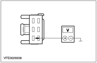
4 Measure the voltage between pin 2 of connector C475, right tail light assembly, circuit 29S-LF20 (orange), from the wiring side, and "weight". |
|
• Does the battery voltage register? |
|
|
→ Yes |
|
|
CHECK the tail light assembly, INSTALL a new one if necessary. Check the correct operation of the system. |
|
|
→ No |
|
|
REPAIR open circuit 29S-LF20 using the wiring diagrams (orange) between CJB and right tail light assembly. Check the correct operation of the system. |
|
|
AI10: RIGHT TAIL LIGHT ASSEMBLY VOLTAGE CHECK (3/5-DOOR VERSION) |
|
|
1 Enter the OFF position. |
|
|
2 Disconnect the C473 right tail light assembly. |
|
|
3 Turn on the SIDE LIGHTS. |
|

|
4 Measure the voltage between pin 1 of connector C473, right tail light assembly, circuit 29S-LF20 (orange), from the wiring side, and "weight". |
|
• Does the battery voltage register? |
|
|
→ Yes |
|
|
CHECK the tail light assembly, INSTALL a new one if necessary. Check the correct operation of the system. |
|
|
→ No |
|
|
REPAIR open circuit 29S-LF20 using the wiring diagrams (orange), between CJB and right tail light assembly. Check the correct operation of the system. |
|
|
AI11: RIGHT TAIL LIGHT ASSEMBLY VOLTAGE CHECK (4-DOOR VERSION) |
|
|
1 Enter the OFF position. |
|
|
2 Disconnect the C477 right tail light assembly. |
|
|
3 Turn on the SIDE LIGHTS. |
|
|
4 Measure the voltage between pin 3 of connector C477, right tail light assembly, circuit 29S-LF20 (orange), from the wiring side, and "weight". |
|
• Does the battery voltage register? |
|
|
→ Yes |
|
|
CHECK the tail light assembly, INSTALL a new one if necessary. Check the correct operation of the system. |
|
|
→ No |
|
|
REPAIR open circuit 29S-LF20 using the wiring diagrams (orange) between CJB and right tail light assembly. Check the correct operation of the system. |
|
|
AI12: LEFT REAR LIGHT ASSEMBLY GROUND ELECTRICAL CHECK |
|
|
1 Drive the ON position. |
|
|
2 Turn on STOP LIGHTS. |
|
|
3 Check the brake lights. |
|
|
• Are the brake lights on? |
|
|
→ Yes |
|
|
"station wagon" Go to AI13 |
|
|
3/5 door variant: Go to AI14 |
|
|
4-door variant: Go to AI15 |
|
|
→ No |
|
|
REPAIR open circuit 31-LE23 using the wiring diagrams (black) between left tail light assembly and splice S184 (grounding point G46). Check the correct operation of the system. |
|
|
AI13: VOLTAGE CHECK IN THE ELECTRICAL CIRCUIT OF THE LEFT REAR LIGHT ASSEMBLY ("UNIVERSAL") |
|
|
1 Enter the OFF position. |
|
|
2 Disconnect the C474 left rear light assembly. |
|
|
3 Turn on the SIDE LIGHTS. |
|

|
4 Measure the voltage between pin 2 of connector C474, left tail light assembly, circuit 29S-LF11 (orange white), from the wiring side, and "weight". |
|
• Does the battery voltage register? |
|
|
→ Yes |
|
|
CHECK the tail light assembly, INSTALL a new one if necessary. Check the correct operation of the system. |
|
|
→ No |
|
|
REPAIR open circuit 29S-LF11 using the wiring diagrams (orange white) between CJB and left tail light assembly. Check the correct operation of the system. |
|
|
AI14: VOLTAGE CHECK IN THE ELECTRICAL CIRCUIT OF THE LEFT REAR LIGHT ASSEMBLY (3/5-DOOR VERSION) |
|
|
1 Enter the OFF position. |
|
|
2 Disconnect the C472 left rear light assembly. |
|
|
3 Turn on the SIDE LIGHTS. |
|
|
4 Measure the voltage between pin 1 of connector C472, left tail light assembly, circuit 29S-LF11 (orange white), from the wiring side, and "weight". |
|
• Does the battery voltage register? |
|
|
→ Yes |
|
|
CHECK the tail light assembly, INSTALL a new one if necessary. Check the correct operation of the system. |
|
|
→ No |
|
|
REPAIR open circuit 29S-LF11 using the wiring diagrams (orange white) between CJB and left tail light assembly. Check the correct operation of the system. |
|
|
AI15: VOLTAGE CHECK IN THE ELECTRICAL CIRCUIT OF THE LEFT REAR LIGHT ASSEMBLY (4-DOOR VERSION) |
|
|
1 Enter the OFF position. |
|
|
2 Disconnect the C476 left rear light assembly. |
|
|
3 Turn on the SIDE LIGHTS. |
|

|
4 Measure the voltage between pin 2 of connector C476, left tail light assembly, circuit 29S-LF11 (orange white), from the wiring side, and "weight". |
|
• Does the battery voltage register? |
|
|
→ Yes |
|
|
CHECK the tail light assembly, INSTALL a new one if necessary. Check the correct operation of the system. |
|
|
→ No |
|
|
REPAIR open circuit 29S-LF11 using the wiring diagrams (orange white) between CJB and left tail light assembly. Check the correct operation of the system. |
|
|
AI16: VOLTAGE TEST OF LICENSE PLATE LIGHT RIGHT CIRCUIT |
|
|
1 Enter the OFF position. |
|
|
2 Disconnect C497 right license plate light. |
|
|
3 Turn on the SIDE LIGHTS. |
|

|
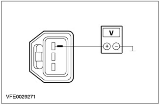
4 Measure the voltage between connector C497 of the right license plate light, circuit 29S-LF22 (orange-black), from the wiring side, and "weight". |
|
• Does the battery voltage register? |
|
|
→ Yes |
|
|
Go to AI17 |
|
|
→ No |
|
|
REPAIR open circuit 29S-LF22 using the wiring diagrams (orange-black) between the left license plate lamp and the right license plate lamp. Check the correct operation of the system. |
|
|
AI17: RIGHT LICENSE PLATE LIGHT GROUND CIRCUIT CHECK |
|
|
1 Disconnect C496 right license plate light. |
|
|
2 Turn off the SIDE LIGHTS. |
|
|
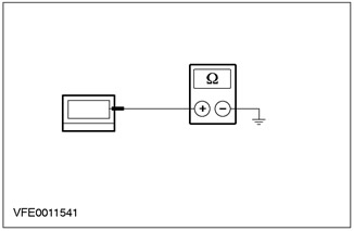
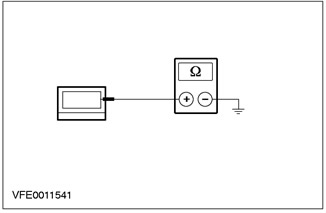
3 Measure the resistance between connector C496 of the right license plate light, circuit 31-LF22 (black), from the wiring side, and "weight". |
|
• Is the resistance less than 2 ohms? |
|
|
→ Yes |
|
|
INSPECT license plate light, INSTALL a new one if necessary. Check the correct operation of the system. |
|
|
→ No |
|
|
REPAIR open circuit 31-LF22 using the wiring diagrams (black) between right license plate light and splice S196 (earthing point G35). Check the correct operation of the system. |
|
|
AI18: LICENSE PLATE LIGHT LEFT GROUND CIRCUIT CHECK |
|
|
1 Disconnect C494 left license plate light. |
|
|
2 Turn off the SIDE LIGHTS. |
|
|
3 Measure the resistance between connector C494, left license plate light, circuit 31-LF21 (black), from the wiring side, and "weight". |
|
• Is the resistance less than 2 ohms? |
|
|
→ Yes |
|
|
INSPECT license plate light, INSTALL a new one if necessary. Check the correct operation of the system. |
|
|
→ No |
|
|
REPAIR open circuit 31-LF21 using the wiring diagrams (black) between left license plate light and splice S196 (earthing point G35). Check the correct operation of the system. |
|
|
AI19: CHECK FUSE F62 (CJB) |
|
|
1 Enter the OFF position. |
|
|
2 CHECK Fuse F62 (CJB). |
|
|
3 Check fuse F62 (7.5 A) |
|
|
• Is the fuse good? |
|
|
→ Yes |
|
|
Go to AI20 |
|
|
→ No |
|
|
INSTALL a new fuse F62 (7.5 A) and TEST the system. If the fuse blows again, LOCATE and REPAIR the short circuit using the wiring diagrams. Check the correct operation of the system. |
|
|
AI20: F62 FUSE VOLTAGE CHECK (CJB) |
|
|
1 Connect Fuse F62 (CJB). |
|
|
2 Turn on the SIDE LIGHTS. |
|
|
3 Measure the voltage between fuse F62 and "weight". |
|
|
• Does the battery voltage register? |
|
|
→ Yes |
|
|
Go to AI21 |
|
|
→ No |
|
|
Go to AI22 |
|
|
AI21: LICENSE PLATE LIGHT LEFT VOLTAGE CHECK |
|
|
1 Disconnect C495 left license plate light. |
|
|
2 Turn on the SIDE LIGHTS. |
|
|
3 Measure the voltage between connector C495 of the left license plate light, circuit 29S-LF21 (orange-black), from the wiring side, and "weight". |
|
• Does the battery voltage register? |
|
|
→ Yes |
|
|
REPAIR open circuit 31-DA13 using the wiring diagrams (A) (black) between splice S196 (earthing point G35) and earth point G15. Check the correct operation of the system. |
|
|
→ No |
|
|
REPAIR open circuit 29S-LF21 using the wiring diagrams (orange-black) between fuse F62 and left license plate light. If necessary, INSTALL a new CJB. Check the correct operation of the system. |
|
|
AI22: LIGHT SWITCH TEST |
|
|
1 Disconnect the C320 light switch. |
|
|
2 Check the light switch as described in chap. "Checking the elements", attached to the wiring diagrams. |
|
|
• Light switch OK? |
|
|
→ Yes |
|
|
License plate lights only not working: Using the wiring diagrams, REPAIR open circuit 29S-LF5 (orange-blue) between light switch and fuse F62 (CJB). If necessary, INSTALL a new CJB. Check the correct operation of the system. |
|
|
Front position and tail lights not working, license plate lights OK: REPAIR open circuit 29S-LF1 using the wiring diagrams (orange yellow) between light switch and fuses F57, F58 (CJB). If necessary, INSTALL a new CJB. Check the correct operation of the system. |
|
|
Parking lights, rear lights and license plate lights not working: Go to AI23 |
|
|
→ No |
|
|
INSTALL a new light switch. Check the correct operation of the system. |
|
|
AI23: FUSE CHECK F30 (CJB) |
|
|
1 Enter the OFF position. |
|
|
2 CHECK Fuse F30 (CJB). |
|
|
3 Check fuse F30 (10 A) |
|
|
• Is the fuse good? |
|
|
→ Yes |
|
|
Go to AI24 |
|
|
→ No |
|
|
INSTALL a new fuse F30 (10 A) and TEST the system. If the fuse blows again, LOCATE and REPAIR the short circuit using the wiring diagrams. Check the correct operation of the system. |
|
|
AI24: CHECK THE VOLTAGE IN THE FUSE CIRCUIT F30 (CJB) |
|
|
1 Connect Fuse F30 (CJB). |
|
|
2 Measure the voltage between fuse F30 and "weight". |
|
|
• Does the battery voltage register? |
|
|
→ Yes |
|
|
REPAIR open circuit 29-LE29 using the wiring diagrams (orange-black) between fuse F30 (CJB) and light switch. If necessary, INSTALL a new CJB. Check the correct operation of the system. |
|
|
→ No |
|
|
Install a new CJB. Check the correct operation of the system. |
|
|
AI25: LIGHT SWITCH VOLTAGE CHECK |
|
|
1 Enter the OFF position. |
|
|
2 Disconnect the C320 light switch. |
|
|
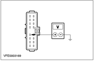
3 Measure the voltage between pin 12 of connector C320, light switch, circuit 30S-LE29A (red-green), from the wiring side, and "weight". |
|
• Does the battery voltage register? |
|
|
→ Yes |
|
|
INSTALL a new light switch. Check the correct operation of the system. |
|
|
→ No |
|
|
Go to AI26 |
|
|
AI26: IGNITION SWITCH CHECK |
|
|
1 Disconnect the C456 ignition switch. |
|
|
2 Install fusible jumper wire (10 A) to connector C456 of the ignition switch, between pin 2, circuit 30S-LE29 (red-green), and pin 4, electrical circuit 30-BB9 (red), from the side of the electrical wiring. |
|
3 Measure the voltage between pin 12 of connector C320, light switch, circuit 30S-LE29A (red-green), from the wiring side, and "weight". |
|
• Does the battery voltage register? |
|
|
→ Yes |
|
|
Install a new ignition switch. Check the correct operation of the system. |
|
|
→ No |
|
|
REPAIR open circuit 30S-LE29 using the wiring diagrams (A) (red-green) between the ignition switch and the light switch. Check the correct operation of the system. |
|
AJ PINPOINT TEST: PARKING LIGHTS, TAIL LIGHTS AND LICENSE PLATE LIGHTS ON PERMANENTLY
|
STATES |
DETAILS/RESULTS/ACTIONS |
|
AJ1: DETECTION OF A SHORT CIRCUIT IN THE ELECTRICAL POWER CIRCUIT |
|
|
1 Enter the OFF position. |
|
|
2 Disconnect Fuse F57 (CJB). |
|
|
3 Drive the ON position. |
|
|
4 Check the parking lights. |
|
|
• Are the right marker lights constantly on? |
|
|
→ Yes |
|
|
Using the wiring diagrams, LOCATE and REPAIR the short to power in the circuit connected to fuse F57 and C17 CJB pin 7. If necessary, INSTALL a new CJB. Check the correct operation of the system. |
|
|
→ No |
|
|
Go to AJ2 |
|
|
AJ2: DETECTION OF A SHORT CIRCUIT IN THE ELECTRICAL POWER CIRCUIT |
|
|
1 Enter the OFF position. |
|
|
2 Disconnect Fuse F58 (CJB). |
|
|
3 Drive the ON position. |
|
|
4 Check the parking lights. |
|
|
• Are the left marker lights constantly on? |
|
|
→ Yes |
|
|
Using the wiring diagrams, LOCATE and REPAIR for a short to power in the circuit between fuse F58 and C17 CJB pin 3. If necessary, INSTALL a new CJB. Check the correct operation of the system. |
|
|
→ No |
|
|
Go to AJ3 |
|
|
AJ3: DETECTION OF A SHORT CIRCUIT IN THE ELECTRICAL POWER CIRCUIT |
|
|
1 Enter the OFF position. |
|
|
2 Disconnect Fuse F62 (CJB). |
|
|
3 Connect Fuse F57 (CJB). |
|
|
4 Connect Fuse F58 (CJB). |
|
|
5 Drive the ON position. |
|
|
6 Check the parking lights. |
|
|
• Are the marker lights constantly on? |
|
|
→ Yes |
|
|
Go to AJ4 |
|
|
→ No |
|
|
Using the wiring diagrams, LOCATE and REPAIR the short to power in the circuit connected to fuses F62 and C16 CJB pin 11. If necessary, INSTALL a new CJB. Check the correct operation of the system. |
|
|
AJ4: DETECTION OF A SHORT CIRCUIT IN THE ELECTRICAL POWER CIRCUIT |
|
|
1 Enter the OFF position. |
|
|
2 Connect Fuse F62 (CJB). |
|
|
3 Disconnect the C320 light switch. |
|
|
4 Drive the ON position. |
|
|
5 Check license plate lights. |
|
|
• Do the license plate lights stay on all the time? |
|
|
→ Yes |
|
|
Go to AJ6 |
|
|
→ No |
|
|
Go to AJ5 |
|
|
AJ5: FAULT CAUSE DETERMINATION |
|
|
1 Check the parking lights. |
|
|
• Are the marker lights constantly on? |
|
|
→ Yes |
|
|
Using the wiring diagrams, LOCATE and REPAIR for a short to power in the circuit connected to fuses F57, F58 and pin 13 of light switch connector C320. If necessary, INSTALL a new CJB. Check the correct operation of the system. |
|
|
→ No |
|
|
INSTALL a new light switch. Check the correct operation of the system. |
|
|
AJ6: DETECTION OF A SHORT CIRCUIT IN THE ELECTRICAL POWER CIRCUIT |
|
|
1 Enter the OFF position. |
|
|
2 Disconnect C104 general electronic module (GEM). |
|
|
3 Drive the ON position. |
|
|
4 Check license plate lights. |
|
|
• Do the license plate lights stay on all the time? |
|
|
→ Yes |
|
|
Using the wiring diagrams, LOCATE and REPAIR the short to power in the circuit connected to fuses F62 and C16 CJB pin 10. If necessary, INSTALL a new CJB. CHECK the system is working properly. |
|
|
→ No |
|
|
Go to AJ7 |
|
|
AJ7: SYSTEM CHECK USING WDS |
|
|
1 Enter the OFF position. |
|
|
2 Connect the C320 light switch. |
|
|
3Connect C104 common electronic module (GEM). |
|
|
4 Connect the diagnostic tool. |
|
|
5 Check the system using WDS. |
|
|
• Are there any DTCs (DTC)? |
|
|
→ Yes |
|
|
PERFORM the necessary actions for the DTCs as instructed by the WDS. CLEAR fault memory and CHECK system for correct operation. |
|
|
→ No |
|
|
INSTALL a new common electronics module (GEM). CHECK the system is working properly. |
|
Visitor comments