|
STATES |
DETAILS/RESULTS/ACTIONS |
|
BA1: DEFINITION OF VEHICLE EQUIPMENT |
|
|
1 Determine the equipment of the car. |
|
|
• Is the vehicle equipped with an automatic transmission? |
|
|
→ Yes |
|
|
Go to BA6 |
|
|
→ No |
|
|
Go to BA2 |
|
|
BA2: FUSE CHECK F53 (CJB) |
|
|
1 Enter the OFF position. |
|
|
2 CHECK Fuse F53 (CJB). |
|
|
3 Check fuse F53 (10 A) |
|
|
• Is the fuse good? |
|
|
→ Yes |
|
|
Go to BA3 |
|
|
→ No |
|
|
INSTALL a new fuse F53 (10 A) and CHECK the system is working properly. If the fuse blows again, LOCATE and REPAIR the short circuit using the wiring diagrams. CHECK the system is working properly. |
|
|
BA3: FUSE VOLTAGE CHECK F53 (CJB) |
|
|
1 Connect Fuse F53 (CJB). |
|
|
2 Drive the ON position. |
|
|
3 Measure the voltage between F53 (CJB) and "mass". |
|
|
• Does the battery voltage register? |
|
|
→ Yes |
|
|
Go to BA4 |
|
|
→ No |
|
|
Using the wiring diagrams, LOCATE and REPAIR the open circuit in the power circuit of fuse F53. If necessary, INSTALL a new CJB.. CHECK the system is working properly. |
|
|
BA4: CHECKING THE ELECTRICAL POWER CIRCUIT OF THE TRANSMISSION SWITCH |
|
|
1 Enter the OFF position. |
|
|
2 Disconnect the C864 transmission switch. |
|
|
3 Drive the ON position. |
|
|
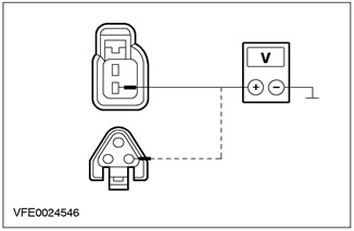
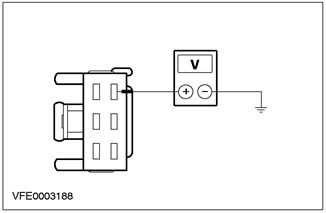
4 Measure the voltage between pin 2 of connector C864 of the transmission switch, circuit 15-LG28 (white-green), from the wiring side, and "ground". |
|
• Does the battery voltage register? |
|
|
→ Yes |
|
|
Go to BA5 |
|
|
→ No |
|
|
LOCATE and REPAIR open circuits using the wiring diagrams 15-LG28 (white-green) and 15-LG28A (white-green) between the fuse and the transmission switch. CHECK the system is working properly. |
|
|
BA5: GEARSHIFT CHECK |
|
|
1 Enter the OFF position. |
|
|
2 Disconnect the C864 transmission switch. |
|
|
3 Install fusible jumper wire (10 A) into connector C864 of the transmission switch between pin 2, circuit 15-LG28 (white-green), from the wiring side, and pin 1, electrical circuit 15S-LG3 (yellow-green), from the side of the electrical wiring. |
|
4 Drive the ON position. |
|
|
5 Check the reversing lights. |
|
|
• Flashlight (And) reverse lights on? |
|
|
→ Yes |
|
|
INSTALL a new transmission switch. CHECK the system is working properly. |
|
|
→ No |
|
|
Reversing light not working (left hand drive variant "station wagon"): Go to BA10 |
|
|
Reversing light not working (right hand drive option "station wagon"): Go to BA11 |
|
|
Reversing lights not working (4-door variant): Go to BA12 |
|
|
Reversing light not working (left-hand drive version, 3/5-door version): Go to BA13 |
|
|
Reversing light not working (right-hand drive version, 3/5-door version): Go to BA14 |
|
|
BA6: FUSE CHECK F40 (CJB) |
|
|
1 Enter the OFF position. |
|
|
2 CHECK Fuse F40 (CJB). |
|
|
3 Check fuse F40 (10 A) |
|
|
• Is the fuse good? |
|
|
→ Yes |
|
|
Go to BA7 |
|
|
→ No |
|
|
INSTALL a new fuse F40 (10 A) and CHECK the system is working properly. If the fuse blows again, LOCATE and REPAIR the short circuit using the wiring diagrams. CHECK the system is working properly. |
|
|
BA7: FUSE VOLTAGE CHECK F40 (CJB) |
|
|
1 Connect Fuse F40 (CJB). |
|
|
2 Drive the ON position. |
|
|
3 Measure the voltage between F40 (CJB) and "mass". |
|
|
• Does the battery voltage register? |
|
|
→ Yes |
|
|
Go to BA8 |
|
|
→ No |
|
|
Using the wiring diagrams, LOCATE and REPAIR the open in the F40 fuse supply circuit. If necessary, INSTALL a new CJB.. CHECK the system is working properly. |
|
|
BA8: CHECK TRANSMISSION RANGE SENSOR POWER CIRCUIT |
|
|
1 Enter the OFF position. |
|
|
2 Disconnect the C438 transmission range sensor. |
|
|
3 Drive the ON position. |
|
|
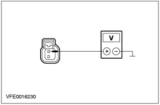
4 Measure voltage between C438 pin 1 of transmission range sensor circuit 15-TA18 (green-orange), from the wiring side, and "ground". |
|
• Does the battery voltage register? |
|
|
→ Yes |
|
|
Go to BA9 |
|
|
→ No |
|
|
LOCATE and REPAIR open circuit 15-TA18 using the wiring diagrams (green-orange) between splice S54 and transmission range sensor. CHECK the system is working properly. |
|
|
BA9: GEARBOX RANGE SENSOR CHECK |
|
|
1 Enter the OFF position. |
|
|
2 Disconnect the C438 transmission range sensor. |
|
|
3 Install fusible jumper wire (10 A) into connector C438 of the transmission range sensor between pin 4, circuit 15S-TA38 (green-blue), and pin 1, electric circuit 15-TA18 (green-orange), from the side of the electrical wiring. |
|
4 Drive the ON position. |
|
|
5 Check the reversing lights. |
|
|
• Flashlight (And) reverse lights on? |
|
|
→ Yes |
|
|
INSTALL a new transmission range sensor. CHECK the system is working properly. |
|
|
→ No |
|
|
Reversing light not working (left hand drive variant "station wagon"): Go to BA10 |
|
|
Reversing light not working (right hand drive option "station wagon"): Go to BA11 |
|
|
Reversing lights not working (4-door variant): Go to BA12 |
|
|
Reversing light not working (left-hand drive version, 3/5-door version): Go to BA13 |
|
|
Reversing light not working (right-hand drive version, 3/5-door version): Go to BA14 |
|
|
BA10: RIGHT TAIL LIGHT ASSEMBLY ELECTRICAL CHECK |
|
|
1 Enter the OFF position. |
|
|
2 Connect C864 transmission switch/ C438 transmission range sensor. |
|
|
3 Disconnect the C475 right tail light assembly. |
|
|
4 Drive the ON position. |
|
|
5 Engage REVERSE GEAR. |
|
|
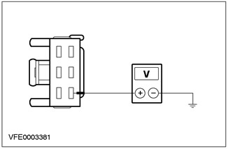
6 Measure the voltage between pin 4 of connector C475, right tail light assembly, circuit 15S-LG9 (black and green), from the wiring side, and "ground". |
|
• Does the battery voltage register? |
|
|
→ Yes |
|
|
LOCATE and REPAIR open circuit 31-LF24A using the wiring diagrams (black) and 31-DA18 (black) between the rear light assembly and ground point G46. INSTALL a new tail light assembly if necessary. CHECK the system is working properly. |
|
|
→ No |
|
|
Using the wiring diagrams, LOCATE and REPAIR the open in the electrical circuits between the transmission switch/transmission range sensor and the tail light assembly. INSTALL a new tail light assembly if necessary. CHECK the system is working properly. |
|
|
BA11: TESTING THE ELECTRICAL POWER CIRCUIT OF THE LEFT REAR LIGHT ASSEMBLY |
|
|
1 Enter the OFF position. |
|
|
2 Connect C864 transmission switch/ C438 transmission range sensor. |
|
|
3 Disconnect the C474 left rear light assembly. |
|
|
4 Drive the ON position. |
|
|
5 Engage REVERSE GEAR. |
|

|
6 Measure the voltage between pin 4 of connector C474, left rear light assembly, circuit 15S-LD6 (yellow-green), from the wiring side, and "ground". |
|
• Does the battery voltage register? |
|
|
→ Yes |
|
|
Using the wiring diagrams, LOCATE and REPAIR open circuit 31-LF23A (black) and 31-DA18 (black) between the rear light assembly and ground. INSTALL a new tail light assembly if necessary. CHECK the system is working properly. |
|
|
→ No |
|
|
Using the wiring diagrams, LOCATE and REPAIR the open in the electrical circuits between the transmission switch/transmission range sensor and the tail light assembly. INSTALL a new tail light assembly if necessary. CHECK the system is working properly. |
|
|
BA12: TESTING THE ELECTRICAL POWER CIRCUIT OF THE LEFT REAR LIGHT ASSEMBLY |
|
|
1 Enter the OFF position. |
|
|
2 Connect C864 transmission switch/ C438 transmission range sensor. |
|
|
3 Disconnect the C476 left rear light assembly. |
|
|
4 Drive the ON position. |
|
|
5 Engage REVERSE GEAR. |
|

|
6 Measure the voltage between pin 4 of connector C476, left tail light assembly, circuit 15S-LG9A (black and green), from the wiring side, and "ground". |
|
• Does the battery voltage register? |
|
|
→ Yes |
|
|
LOCATE and REPAIR open circuit 31-DA18 using the wiring diagrams (black) between splice S184, and earth point G46. CHECK the system is working properly. |
|
|
→ No |
|
|
Using the wiring diagrams, LOCATE and REPAIR the open in the circuits between the transmission switch/transmission range sensor and splice S211. CHECK the system is working properly. |
|
|
BA13: RIGHT REVERSE LIGHT ELECTRICAL CHECK |
|
|
1 Enter the OFF position. |
|
|
2 Connect C864 transmission switch/ C438 transmission range sensor. |
|
|
3 Disconnect the C430 right reversing light. |
|
|
4 Drive the ON position. |
|
|
5 Engage REVERSE GEAR. |
|
|
6 Measure the voltage between pin 1 of connector C430, right reversing light, circuit 15S-LG9 (black and green), from the wiring side, and "ground". |
|
• Does the battery voltage register? |
|
|
→ Yes |
|
|
LOCATE and REPAIR open circuit 31-LG9 using the wiring diagrams (black) and 31-DA18 (black) between the reversing light and earth point G46. INSTALL a new reversing light if necessary. CHECK the system is working properly. |
|
|
→ No |
|
|
Using the wiring diagrams, LOCATE and REPAIR the open circuits between the transmission switch/transmission range sensor and the reverse lamp. INSTALL a new reversing light if necessary. CHECK the system is working properly. |
|
|
BA14: CHECK THE ELECTRICAL POWER CIRCUIT OF THE LEFT REVERSE LAMP |
|
|
1 Enter the OFF position. |
|
|
2 Connect C864 transmission switch/ C438 transmission range sensor. |
|
|
3 Disconnect the C434 right tail light assembly. |
|
|
4 Drive the ON position. |
|
|
5 Engage REVERSE GEAR. |
|

|
6 Measure the voltage between pin 1 of connector C434 left reversing light circuit 15S-LD6 (yellow-green), from the wiring side, and "ground". |
|
• Does the battery voltage register? |
|
|
→ Yes |
|
|
LOCATE and REPAIR open circuit 31-LD6 using the wiring diagrams (black) and 31-DA18 (black) between the reversing light and earth point G46. INSTALL a new reversing light if necessary. CHECK the system is working properly. |
|
|
→ No |
|
|
Using the wiring diagrams, LOCATE and REPAIR the open in the electrical circuits between the transmission switch/transmission range sensor and the reverse lamp. INSTALL a new reversing light if necessary. CHECK the system is working properly. |
|
PINPOINT TEST BB: SEPARATE REVERSE LAMP DOES NOT WORK
|
STATES |
DETAILS/RESULTS/ACTIONS |
|
BB1: REVERSING LIGHT OUT OF WORK DETECTION |
|
|
1 Drive the ON position. |
|
|
2 Engage REVERSE GEAR. |
|
|
3 Check the reversing lights. |
|
|
• Left reversing light not working? |
|
|
→ Yes |
|
|
Go to BB2 |
|
|
→ No |
|
|
Go to BB3 |
|
|
BB2: LEFT REVERSE LAMP CHECK |
|
|
1 Enter the OFF position. |
|
|
2 Disconnect the C476 left rear light assembly. |
|
|
3 Drive the ON position. |
|
|
4 Engage REVERSE GEAR. |
|

|
5 Measure the voltage between pin 4 of connector C476, left tail light assembly, circuit 15S-LG9A (black and green), from the wiring side, and "ground". |
|
• Does the battery voltage register? |
|
|
→ Yes |
|
|
Using the wiring diagrams, LOCATE and REPAIR open circuit 31-LF23 (black) between tail light assembly and splice S184. INSTALL a new tail light assembly if necessary. CHECK the system is working properly. |
|
|
→ No |
|
|
LOCATE and REPAIR open circuit 15S-LG9A using the wiring diagrams (black and green) between tail light assembly and splice S211. INSTALL a new tail light assembly if necessary. CHECK the system is working properly. |
|
|
BB3: RIGHT REVERSE LIGHT CHECK |
|
|
1 Enter the OFF position. |
|
|
2 Disconnect the C477 right tail light assembly. |
|
|
3 Drive the ON position. |
|
|
4 Engage REVERSE GEAR. |
|
|
5 Measure the voltage between pin 6 of connector C477, right tail light assembly, circuit 15S-LG16 (green-orange), from the wiring side, and "ground". |
|
• Does the battery voltage register? |
|
|
→ Yes |
|
|
LOCATE and REPAIR open circuit 31-LF24 using the wiring diagrams (black) between tail light assembly and splice S184. INSTALL a new tail light assembly if necessary. CHECK the system is working properly. |
|
|
→ No |
|
|
LOCATE and REPAIR open circuit 15S-LG16 using the wiring diagrams (green-orange) between tail light assembly and splice S211. INSTALL a new tail light assembly if necessary. CHECK the system is working properly. |
|
PINPOINT TEST BC: REVERSING LIGHTS ON PERMANENTLY
|
STATES |
DETAILS/RESULTS/ACTIONS |
|
BC1: SYSTEM CHECK USING WDS |
|
|
1 Connect the diagnostic tool. |
|
|
2 Check the system using WDS. |
|
|
• Are there any DTCs (DTC)? |
|
|
→ Yes |
|
|
Take appropriate action on DTCs as directed by WDS. CLEAR fault memory and CHECK system for correct operation. |
|
|
→ No |
|
|
Manual Transmission Vehicles: Go to BC2 |
|
|
Vehicles with automatic transmission: Go to BC3 |
|
|
BC2: TRANSMISSION SWITCH CHECK |
|
|
1 Enter the OFF position. |
|
|
2 Disconnect the C864 transmission switch. |
|
|
3 Drive the ON position. |
|
|
4 Check the lantern (And) reverse. |
|
|
• Flashlight (And) reverse lights on? |
|
|
→ Yes |
|
|
Using the wiring diagrams, LOCATE and REPAIR short to power on circuits connected to splice S92. CHECK the system is working properly. |
|
|
→ No |
|
|
INSTALL a new transmission switch. CHECK the system is working properly. |
|
|
BC3: GEARBOX RANGE SENSOR CHECK |
|
|
1 Enter the OFF position. |
|
|
2 Disconnect the C438 transmission switch. |
|
|
3 Drive the ON position. |
|
|
4 Check the lantern (And) reverse. |
|
|
• Flashlight (And) reverse lights on? |
|
|
→ Yes |
|
|
Using the wiring diagrams, LOCATE and REPAIR the short to power circuit in circuits connected to splice S75. CHECK the system is working properly. |
|
|
→ No |
|
|
INSTALL a new transmission range sensor. CHECK the system is working properly. |
|
Visitor comments