|
STATES |
DETAILS/RESULTS/ACTIONS |
|
AF1: IDENTIFY WHICH LAMP IS DEFECTIVE. |
|
|
1 Determine the state in which the fault occurs. |
|
|
• Parking lights, rear lights, or license plate lights not working in any position of the light switch? |
|
|
→ Yes |
|
|
Go to AF2 |
|
|
→ No |
|
|
Light switch in position "parking" and ignition off: Go to AF4 |
|
|
Light switch in position "parking lights" or "dipped beam": Go to AF6 |
|
|
Daytime running lights, light switch in position "Turned off" and ignition on: Go to AF9 |
|
|
With daytime running lights, light switch in position "Parking lights" and ignition on: Go to AF10 |
|
|
AF2: CHECK CJB |
|
|
1 Enter the OFF position. |
|
|
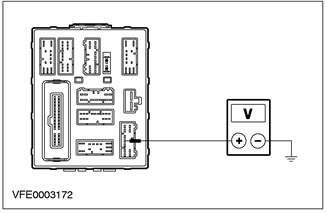
2 Disconnect C16 CJB. |
|
|
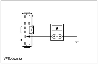
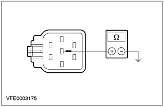
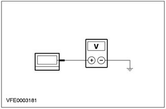
3 Measure the voltage between pin 6 of connector C16 CJB, circuit 29S-LF1 (orange yellow), from the wiring side, and "weight". |
|
• Does the meter show battery voltage? |
|
|
→ Yes |
|
|
REPLACE CJB. CHECK the system is working properly. |
|
|
→ No |
|
|
Go to AF3 |
|
|
AF3: INSPECT ELECTRICAL CIRCUIT 29S-LF1 |
|
|
1 Disconnect the C320 light switch. |
|
|
2 Disconnect C16 CJB. |
|
|
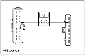
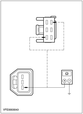
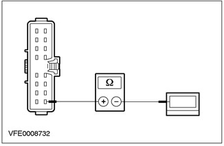
3 Measure the resistance between pin 13 of connector C320, light switch, circuit 29S-LF1 (orange yellow), on the wiring side, and pin 6 of the C16 CJB connector, on the wiring side. |
|
• Is the resistance less than 2 ohms? |
|
|
→ Yes |
|
|
REPLACE light switch. CHECK the system is working properly. |
|
|
→ No |
|
|
REPAIR circuit 29S-LF1. CHECK the system is working properly. |
|
|
AF4: CHECK LIGHT SWITCH |
|
|
1 Enter the OFF position. |
|
|
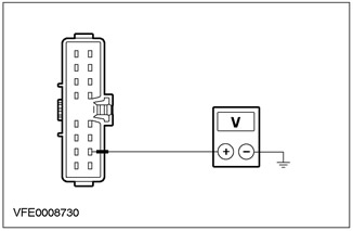
2 Disconnect the C320 light switch. |
|

|
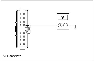
3 Measure voltage between pin 12 of connector C320 of light switch, circuit 30S-LE29 (red-green), from the wiring side, and "weight". |
|
• Does the meter show battery voltage? |
|
|
→ Yes |
|
|
Replace light switch. CHECK the system is working properly. |
|
|
→ No |
|
|
Go to AF5 |
|
|
AF5: INSPECT 30S-LE29 AND/OR 30S-LE29A CIRCUIT |
|
|
1 Disconnect the C456 ignition switch. |
|
|
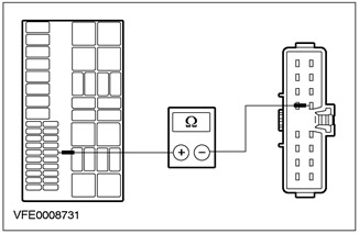
2 Measure the resistance between pin 2 of connector C456 ignition switch circuit 30S-LE29 and/or 30S-LE29A (red-green), on the wiring side, and pin 12 of connector C320 of the light switch, on the wiring side. |
|
• Is the resistance less than 2 ohms? |
|
|
→ Yes |
|
|
REPLACE ignition switch. CHECK the system is working properly. |
|
|
→ No |
|
|
REPAIR circuit 30S-LE29 and/or 30S-LE29A. CHECK the system is working properly. |
|
|
AF6: CHECK FUSE F32 |
|
|
1 Disconnect Fuse F32 (10 A) (CJB). |
|
|
2 Check fuse F32 |
|
|
• Fuse F32 (10 A) (CJB) serviceable? |
|
|
→ Yes |
|
|
Go to AF7 |
|
|
→ No |
|
|
REPLACE fuse F32. If fuse F32 fails again, FIND and REPAIR the short circuit using the wiring diagrams. CHECK the system is working properly. |
|
|
AF7: CHECK LIGHT SWITCH |
|
|
1 Enter the OFF position. |
|
|
2 Disconnect the C320 light switch. |
|
|
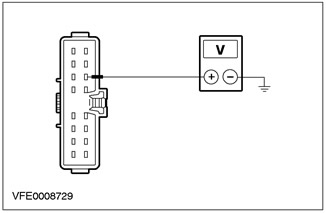
3 Measure the voltage between pin 11 of connector C320, light switch, circuit 29-LE29 (orange-black), from the wiring side, and "weight". |
|
• Does the meter show battery voltage? |
|
|
→ Yes |
|
|
REPLACE light switch. CHECK the system is working properly. |
|
|
→ No |
|
|
Go to AF8 |
|
|
AF8: CHECK CJB |
|
|
1 Measure the voltage between C17 CJB pin 8, element side, and "weight". |
|
• Does the meter show battery voltage? |
|
|
→ Yes |
|
|
REPAIR circuit 29-LE29. CHECK the system is working properly. |
|
|
→ No |
|
|
REPLACE CJB. CHECK the system is working properly. |
|
|
AF9: CHECK GROUND CONNECTION AT REAR LEFT TURN SIGNAL LAMP AREA |
|
|
1 Enter the OFF position. |
|
|
2 Disconnect the C320 light switch. |
|
|
3 Drive the ON position. |
|
|
4 Measure voltage between pin 15 C320 of light switch, circuit 15S-LE29 (green-black), from the wiring side, and "weight". |
|
• Does the meter show battery voltage? |
|
|
→ Yes |
|
|
REPLACE light switch. CHECK the system is working properly. |
|
|
→ No |
|
|
See Section 417-04 for more information. |
|
|
AF10: INSPECT FUSE F14 BJB. |
|
|
1 CHECK Fuse F14. |
|
|
2 Check fuse F14 |
|
|
• Fuse F14 (BJB) serviceable? |
|
|
→ Yes |
|
|
Go to AF11 |
|
|
→ No |
|
|
REPLACE fuse F14. If fuse F14 fails again, FIND and REPAIR the short circuit using the wiring diagrams. CHECK the system is working properly. |
|
|
AF11: INSPECT 30S-LE29 AND/OR 30S-LE29A CIRCUIT |
|
|
1 Disconnect the C320 light switch. |
|
|
2 Measure the resistance between fuse F14 and pin 12 of connector C320 of light switch circuit 30S-LE29 / 30S-LE29A (red-green), from the side of the electrical wiring. |
|
• Is the resistance less than 2 ohms? |
|
|
→ Yes |
|
|
Replace light switch. CHECK the system is working properly. |
|
|
→ No |
|
|
REPAIR circuit 30S-LE29 and/or 30S-LE29A. CHECK the system is working properly. |
|
PINPOINT TEST AG: ONE OR MORE PARKING LIGHTS, REAR LIGHTS OR LICENSE PLATE LIGHTS DO NOT WORK
|
STATES |
DETAILS/RESULTS/ACTIONS |
|
AG1: IDENTIFY THE STATE IN WHICH THE FAULT IS APPEARING |
|
|
1 Enter the OFF position. |
|
|
2 Set the light switch to "parking lights". |
|
|
3 Determine the state in which the fault occurs. |
|
|
• Parking lights and taillights not working? |
|
|
→ Yes |
|
|
Go to AG2 |
|
|
→ No |
|
|
Tail lights not working: Go to AG8 |
|
|
License plate lights not working: Go to AG14 |
|
|
AG2: IDENTIFY THE STATE IN WHICH THE FAULT APPEARS |
|
|
1 Check the operation of the right parking lights and rear lights. |
|
|
• Right parking light and tail light not working? |
|
|
→ Yes |
|
|
Go to AG7 |
|
|
→ No |
|
|
Right parking light not working: Go to AG3 |
|
|
Left parking light not working: Go to AG5 |
|
|
AG3: INSPECT ELECTRICAL CIRCUIT 29S-LF16 |
|
|
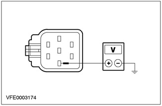
1 Disconnect the C834 right headlight. |
|
|
2 Measure the voltage between pin 3 of connector C834 of the right headlight, circuit 29S-LF16 (orange green), from the wiring side, and "weight". |
|
• Does the meter show battery voltage? |
|
|
→ Yes |
|
|
Go to AG4 |
|
|
→ No |
|
|
REPAIR circuit 29S-LF16. CHECK the system is working properly. |
|
|
AG4: CHECK ELECTRICAL CIRCUIT 31-LE30 AT GROUND SITE |
|
|
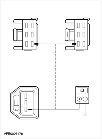
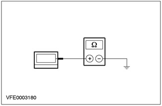
1 Measure the resistance between pin 4 of connector C834, right headlight, circuit 31-LE30 (black), from the wiring side, and "weight". |
|
• Is the resistance less than 2 ohms? |
|
|
→ Yes |
|
|
REPLACE the right headlight after checking the bulb. CHECK the system is working properly. |
|
|
→ No |
|
|
REPAIR circuit 31-LE30 at ground area. CHECK the system is working properly. |
|
|
AG5: INSPECT ELECTRICAL CIRCUIT 29S-LF7 |
|
|
1 Disconnect the left headlight C835. |
|

|
2 Measure the voltage between pin 3 of connector C835, left headlight, circuit 29S-LF7 (orange-blue), from the wiring side, and "weight". |
|
• Does the meter show battery voltage? |
|
|
→ Yes |
|
|
Go to AG6 |
|
|
→ No |
|
|
REPAIR circuit 29S-LF7. CHECK the system is working properly. |
|
|
AG6: CHECK ELECTRICAL CIRCUIT 31-LE31 AT GROUND SITE |
|

|
1 Measure the resistance between pin 4 of connector C835, left headlight, circuit 31-LE31 (black), from the wiring side, and "weight". |
|
• Is the resistance less than 2 ohms? |
|
|
→ Yes |
|
|
REPLACE the left headlight after checking the bulb. CHECK the system is working properly. |
|
|
→ No |
|
|
REPAIR circuit 31-LE31 at ground area. CHECK the system is working properly. |
|
|
AG7: CHECK F48 FUSE |
|
|
1 Enter the OFF position. |
|
|
2CHECK F48 (7.5 A) (CJB). |
|
|
3 Check fuse F48 (7.5 A) (CJB). |
|
|
• Is fuse F48 OK? |
|
|
→ Yes |
|
|
REPLACE CJB. CHECK the system is working properly. |
|
|
→ No |
|
|
REPLACE fuse F48. If fuse F48 fails again, FIND and REPAIR the short circuit using the wiring diagrams. CHECK the system is working properly. |
|
|
AG8: IDENTIFY THE FAULTY STATE |
|
|
1 Check the operation of the left parking light and tail light. |
|
|
• Left parking light and tail light not working? |
|
|
→ Yes |
|
|
Go to AG13 |
|
|
→ No |
|
|
Right tail light not working: Go to AG9 |
|
|
Left tail light not working: Go to AG11 |
|
|
AG9: INSPECT ELECTRICAL CIRCUIT 29S-LF20 |
|

|
1 Disconnect C473, C477 or C475 of the right rear light assembly. |
|
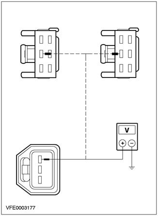
2 Measure the voltage between the pins of the right rear light assembly: - 3-door and 5-door: pin 1 of connector C473, - 4-door version: by pin 3 connector C477, - "station wagon": pin 2 connector C475, - electrical circuit 29S-LF20 (orange), from the wiring side, and "weight". |
|
|
• Does the meter show battery voltage? |
|
|
→ Yes |
|
|
Go to AG10 |
|
|
→ No |
|
|
REPAIR circuit 29S-LF20. CHECK the system is working properly. |
|
|
AG10: CHECK 31-LF24 ELECTRICAL CIRCUIT AT GROUND SITE |
|
|
1 Measure the resistance between the pins of the right rear light assembly: - 3 and 5 door versions: C473 connector pin 3, - 4-door version: by pin 4 connector C477, - "station wagon": pin 3 connector C475, - electrical circuit 31-LF24 (black), from the wiring side, and "weight". |
|
• Is the resistance less than 2 ohms? |
|
|
→ Yes |
|
|
REPLACE the right rear light assembly after checking the bulb. CHECK the system is working properly. |
|
|
→ No |
|
|
REPAIR circuit 31-LE24 at ground area. CHECK the system is working properly. |
|
|
AG11: INSPECT ELECTRICAL CIRCUIT 29S-LF11 |
|
|
1 Disconnect C472, C476 or C474 of the left rear light assembly. |
|
2 Measure the voltage between the pins of the left rear light assembly - 3 and 5 door versions: pin 1 connector C472, - 4-door version: by pin 2 connector C476, - "station wagon": pin 2 connector C474, - electrical circuit 29S-LF11 (orange white), from the wiring side, and "weight". |
|
|
• Does the meter show battery voltage? |
|
|
→ Yes |
|
|
Go to AG12 |
|
|
→ No |
|
|
REPAIR circuit 29S-LF11. CHECK the system is working properly. |
|
|
AG12: CHECK ELECTRICAL CIRCUIT 31-LF23 AT GROUND SITE |
|
|
1 Measure the resistance between the pins of the left rear light assembly, - 3 and 5 door versions: by pin 3 connector C472, - 4-door version: pin 6 connector C476, - "station wagon": pin 3 connector C474, - electrical circuit 31-LF23 (black), from the wiring side, and "weight". |
|
• Is the resistance less than 2 ohms? |
|
|
→ Yes |
|
|
REPLACE the left rear light assembly after checking the bulb. CHECK the system is working properly. |
|
|
→ No |
|
|
REPAIR circuit 31-LF23 at ground area. CHECK the system is working properly. |
|
|
AG13: CHECK F47 FUSE |
|
|
1 Enter the OFF position. |
|
|
2CHECK F47 (7.5 A) (CJB). |
|
|
3 Check fuse F47 (7.5 A) (CJB). |
|
|
• Is the fuse good? |
|
|
→ Yes |
|
|
REPLACE CJB. CHECK the system is working properly. |
|
|
→ No |
|
|
REPLACE fuse F47. If fuse F47 fails again, FIND and REPAIR the short circuit using the wiring diagrams. CHECK the system is working properly. |
|
|
AG14: IDENTIFY THE FAULT STATE |
|
|
1 Check the operation of the license plate lights. |
|
|
• Is the right license plate light not working? |
|
|
→ Yes |
|
|
Go to AG17 |
|
|
→ No |
|
|
Left license plate light not working: Go to AG16 |
|
|
Both license plate lights not working: Go to AG15 |
|
|
AG15: INSPECT ELECTRICAL CIRCUIT 29S-LF21 |
|
|
1 Disconnect the C320 light switch. |
|
|
2 Disconnect C495 left license plate light. |
|
|
3 Measure the resistance between pin 16 of connector C320, light switch, circuit 29S-LF21 (orange-black), on the wiring side, and pin 1 C495 of the left license plate light, on the wiring side. |
|
• Is the resistance less than 2 ohms? |
|
|
→ Yes |
|
|
Replace light switch. CHECK the system is working properly. |
|
|
→ No |
|
|
REPAIR circuit 29S-LF21. CHECK the system is working properly. |
|
|
AG16: CHECK 31-LF21 ELECTRICAL CIRCUIT AT GROUND SITE |
|
|
1 Disconnect C494 left license plate light. |
|
|
2 Measure the resistance between pin 1 of connector C494, left license plate light, circuit 31-LF21 (black), from the wiring side, and "weight". |
|
• Is the resistance less than 2 ohms? |
|
|
→ Yes |
|
|
REPLACE the left license plate lamp after checking the lamp. CHECK the system is working properly. |
|
|
→ No |
|
|
REPAIR circuit 31-LF21. CHECK the system is working properly. |
|
|
AG17: INSPECT ELECTRICAL CIRCUIT 29S-LF22 |
|
|
1 Disconnect C497 right license plate light. |
|
|
2 Measure the voltage between pin 1 of connector C497, right license plate light, circuit 29S-LF22 (orange-black), from the wiring side, and "weight". |
|
• Does the meter show battery voltage? |
|
|
→ Yes |
|
|
Go to AG18 |
|
|
→ No |
|
|
REPAIR circuit 29S-LF22. CHECK the system is working properly. |
|
|
AG18: CHECK 31-LF22 ELECTRICAL CIRCUIT AT GROUND SITE |
|
|
1 Disconnect the C496 right license plate light. |
|

|
2 Measure the resistance between pin 1 of connector C496, right license plate light, circuit 31-LF22 (black), from the wiring side, and "weight". |
|
• Is the resistance less than 2 ohms? |
|
|
→ Yes |
|
|
After checking the lamp, REPLACE the right license plate lamp. CHECK the system is working properly. |
|
|
→ No |
|
|
REPAIR circuit 31-LF22. CHECK the system is working properly. |
|
PINPOINT TEST AH: PARKING LIGHTS, REAR LIGHTS OR LICENSE PLATE LIGHTS ON PERMANENTLY
|
STATES |
DETAILS/RESULTS/ACTIONS |
|
AH1: IDENTIFY THE FAULTY STATUS |
|
|
1 Drive the ON position. |
|
|
2 Check that the parking lights, tail lights, and license plate lights are on at all times. |
|
|
• All parking lights, rear lights, and license plate lights are permanently on in the light switch position "Turned off"? |
|
|
→ Yes |
|
|
Go to AH4 |
|
|
→ No |
|
|
All parking lights, taillights and license plate lamps are permanently on when the light switch is in the position "parking"? |
|
|
For vehicles without daytime running lights: Go to AH2 |
|
|
For vehicles with daytime running lights: Go to AH3 |
|
|
AH2: CHECK IGNITION SWITCH |
|
|
1 Enter the OFF position. |
|
|
2 Disconnect the C456 ignition switch. |
|
|
3 Check the ignition switch for a short circuit. |
|
|
• All taillights and parking lights permanently on in light switch position "parking"? |
|
|
→ Yes |
|
|
REPAIR circuit 30S-LE29. CHECK the system is working properly. |
|
|
→ No |
|
|
REPLACE ignition switch. CHECK the system is working properly. |
|
|
AH3: INSPECT IGNITION SWITCH / ELECTRICAL 30S-LE29, 30S-LE29A. |
|
|
1 Enter the OFF position. |
|
|
2 Disconnect the C456 ignition switch. |
|
|
3 Disconnect Fuse F14 (10 A) (BJB). |
|
|
4 Check ignition switch/circuit 30S-LE29, 30S-LE29A. |
|
|
• All taillights and parking lights permanently on in light switch position "parking"? |
|
|
→ Yes |
|
|
REPAIR circuit 30S-LE29 and/or 30S-LE29A. CHECK the system is working properly. |
|
|
→ No |
|
|
REPLACE ignition switch. CHECK the system is working properly. |
|
|
AH4: CHECK LIGHT SWITCH |
|
|
1 Enter the OFF position. |
|
|
2 Disconnect the C320 light switch. |
|
|
3 Drive the ON position. |
|
|
4 Check that the parking lights, rear lights and license plate lights are on at all times. |
|
|
• Are all parking lights and taillights on at all times? |
|
|
→ Yes |
|
|
Go to AH5 |
|
|
→ No |
|
|
License plate lights permanently on: Go to AH7 |
|
|
License plate lights not on all the time, vehicles without daytime running lights: REPLACE light switch. CHECK the system is working properly. |
|
|
License plate lights not on all the time, vehicles with daytime running lights: Refer to Section 417-04 for more information. |
|
|
AH5: CHECK CJB |
|
|
1 Enter the OFF position. |
|
|
2 Disconnect C16 CJB. |
|
|
3 Drive the ON position. |
|
|
4 Check that all parking lights, tail lights, and license plate lights come on at all times. |
|
|
• Are the parking lights and taillights on all the time? |
|
|
→ Yes |
|
|
Right parking lights and tail lights always on: REPAIR circuit 29S-LF20 or 29S-LF16. CHECK the system is working properly. |
|
|
Left parking lights and tail lights always on: REPAIR circuit 29S-LF11 or 29S-LF7. CHECK the system is working properly. |
|
|
→ No |
|
|
Go to AH6 |
|
|
AH6: INSPECT ELECTRICAL CIRCUIT 29S-LF1 |
|

|
1 Measure the voltage between pin 6 of connector C16 CJB, circuit 29S-LF1, wiring side, and "weight". |
|
• Does the meter show battery voltage? |
|
|
→ Yes |
|
|
REPAIR circuit 29S-LF1. CHECK the system is working properly. |
|
|
→ No |
|
|
REPLACE CJB. CHECK the system is working properly. |
|
|
AH7: CHECK CENTRAL TIMER MODULE |
|
|
1 Disconnect the C1000 CTM. |
|
|
2 Check the central timer module (CTM) for a short circuit |
|
|
• Are the license plate lights on all the time? |
|
|
→ Yes |
|
|
Go to AH8 |
|
|
→ No |
|
|
REPLACE CTM. CHECK the system is working properly. |
|
|
AH8: CHECK CJB |
|
|
1 Disconnect C15 CJB. |
|
|
2 Check the CJB for a short circuit. |
|
|
• Are the license plate lights on all the time? |
|
|
→ Yes |
|
|
REPAIR circuit 29S-LE18, 29S-LF21, or 29S-LF22. CHECK the system is working properly. |
|
|
→ No |
|
|
REPLACE CJB. CHECK the system is working properly. |
|
Visitor comments