|
STATES |
DETAILS/RESULTS/ACTIONS |
|
AB1: SYSTEM CHECK USING WDS |
|
|
1 Connect the diagnostic tool. |
|
|
2 Check the system using WDS. |
|
|
• Are there any DTCs (DTC)? |
|
|
→ Yes |
|
|
PERFORM the necessary actions for the DTCs as instructed by the WDS. CLEAR fault memory and CHECK system for correct operation. |
|
|
→ No |
|
|
Go to AB2 |
|
|
AB2: FUSE CHECK F32 (CJB) |
|
|
1 Enter the OFF position. |
|
|
2CHECK Fuse F32 (CJB). |
|
|
3 Check fuse F32 (15 A) |
|
|
• Is the fuse good? |
|
|
→ Yes |
|
|
Go to AB3 |
|
|
→ No |
|
|
INSTALL a new fuse F32 (15 A) and CHECK the system is working properly. If the fuse blows again, Using the wiring diagrams, FIND and REPAIR the short circuit using the wiring diagrams. CHECK the system is working properly. |
|
|
AB3: CHECK FUSE VOLTAGE F32 (CJB) |
|
|
1 Connect Fuse F32 (CJB). |
|
|
2 Drive the ON position. |
|
|
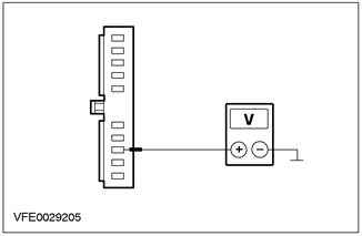
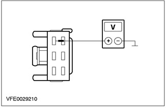
3 Measure the voltage between F32 (CJB) and "mass". |
|
|
• Does the battery voltage register? |
|
|
→ Yes |
|
|
Go to AB4 |
|
|
→ No |
|
|
Using the wiring diagrams, RESTORE power to fuse F32. If necessary, INSTALL a new CJB. CHECK the system is working properly. |
|
|
AB4: COMMON ELECTRONIC MODULE GROUND ELECTRICAL CIRCUIT CHECK (GEM) |
|
|
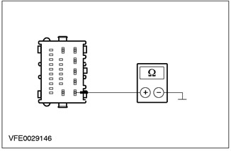
1 Disconnect C104 General Electronics Module (GEM). |
|
|
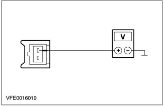
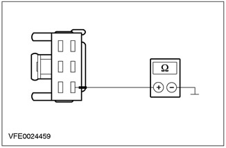
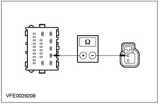
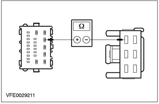
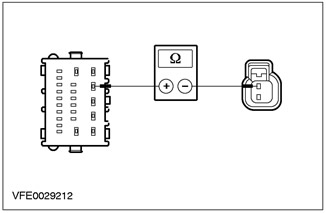
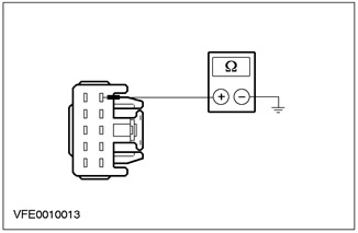
2 Measure the resistance between pin 1 of connector C104 of the common electronic module (GEM), electrical circuit 91-DK20 (black and red), from the wiring side, and "ground". |
|
• Is the resistance less than 2 ohms? |
|
|
→ Yes |
|
|
Go to AB5 |
|
|
→ No |
|
|
LOCATE and REPAIR open circuit 91-DK20 using the wiring diagrams (black and red) and respectively 91-DA2 (black and blue), between common electronic module (GEM) and earth point G41. CHECK the system is working properly. |
|
|
AB5: DETERMINING THE STATE IN WHICH THE FAULT IS APPEARING |
|
|
1 Drive the ON position. |
|
|
2 Check the direction indicators. |
|
|
• Are all direction indicators on constantly? |
|
|
→ Yes |
|
|
INSTALL a new common electronics module (GEM). CHECK the system is working properly. |
|
|
→ No |
|
|
Direction indicators flashing continuously: Go to AB8 |
|
|
All turn signals off: Go to AB6 |
|
|
AB6: DETERMINING THE STATE IN WHICH THE FAULT IS MANIFESTED |
|
|
1 Turn on the left and right SIGNALS sequentially. |
|
|
2 Check the direction indicators. |
|
|
• Are all turn signals out of order? |
|
|
→ Yes |
|
|
Go to AB7 |
|
|
→ No |
|
|
Go to AD PINPOINT TEST |
|
|
AB7: TURN SIGNAL SWITCH CHECK |
|
|
1 Enter the OFF position. |
|
|
2 Disconnect the C459 turn signal switch. |
|
|
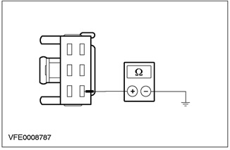
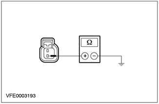
3 Measure the resistance between pin 2 of connector C459 turn signal switch circuit 91-LG27 (black and green), from the wiring side, and "ground". |
|
• Is the resistance less than 2 ohms? |
|
|
→ Yes |
|
|
INSTALL a new turn signal switch. CHECK the system is working properly. |
|
|
→ No |
|
|
LOCATE and REPAIR open circuit 91-LG27 using the wiring diagrams (black and green) between the turn signal switch and splice S12. CHECK the system is working properly. |
|
|
AB8: HAZARD LIGHT SWITCH TEST |
|
|
1 Enter the OFF position. |
|
|
2 Disconnect the C458 hazard warning light switch. |
|
|
3 Drive the ON position. |
|
|
4 Check the direction indicators. |
|
|
• Are the turn signals constantly flashing? |
|
|
→ Yes |
|
|
Go to AB9 |
|
|
→ No |
|
|
INSTALL a new hazard warning light switch. CHECK the system is working properly. |
|
|
AB9: 91S-LG8 ELECTRICAL CIRCUIT CHECK (BLACK AND ORANGE) FOR A SHORT TO GROUND |
|
|
1 Enter the OFF position. |
|
|
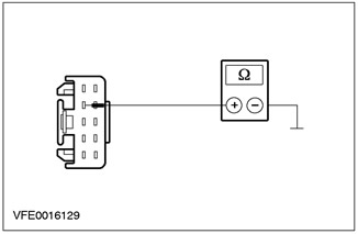
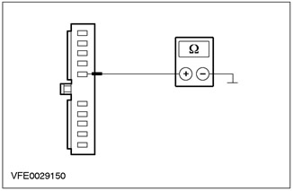
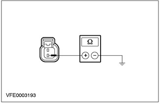
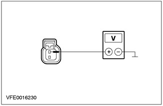
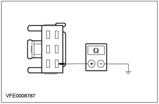
2 Measure the resistance between pin 4 of connector C458 of the hazard warning light switch, circuit 91S-LG8 (black-orange), from the wiring side, and "ground". |
|
• Is the resistance greater than 10 kΩ? |
|
|
→ Yes |
|
|
CHECK the common electronic module (GEM), if necessary, INSTALL a new one. CHECK the system is working properly. |
|
|
→ No |
|
|
Using the wiring diagrams, LOCATE and REPAIR short to ground in circuit 91S-LG8 (black-orange) between common electronic module (GEM) and an emergency light switch. CHECK the system is working properly. |
|
PINPOINT TEST AC: HAZARD LIGHTS DO NOT WORK
|
STATES |
DETAILS/RESULTS/ACTIONS |
|
AC1: HAZARD LIGHT SWITCH GROUND ELECTRICAL CHECK |
|
|
1 Enter the OFF position. |
|
|
2 Disconnect the C458 hazard warning light switch. |
|
|
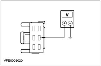
3 Measure the resistance between pin 5 of connector C458 of the hazard warning light switch, circuit 91-LG8 (black-orange), from the wiring side, and "ground". |
|
• Is the resistance less than 2 ohms? |
|
|
→ Yes |
|
|
Go to AC2 |
|
|
→ No |
|
|
LOCATE and REPAIR open circuit 91-LG8 using the wiring diagrams (black-orange) between the hazard warning light switch and splice S12. CHECK the system is working properly. |
|
|
AC2: HAZARD LIGHT SWITCH TEST |
|
|
1 Install fusible jumper wire (10 A) to connector C458 of the hazard warning light switch between pin 4, circuit 91S-LG8 (black-orange), and pin 5, electrical circuit 91-LG8 (black and blue), from the side of the electrical wiring. |
|
2 Check the direction indicators. |
|
|
• Are the hazard warning lights working correctly? |
|
|
→ Yes |
|
|
INSTALL a new hazard warning light switch. CHECK the system is working properly. |
|
|
→ No |
|
|
Go to AC3 |
|
|
AC3: SYSTEM CHECK USING WDS |
|
|
1 Connect the diagnostic tool. |
|
|
2 Check the system using WDS. |
|
|
• Are there any DTCs (DTC)? |
|
|
→ Yes |
|
|
PERFORM the necessary actions for the DTCs as instructed by the WDS. CLEAR fault memory and CHECK system for correct operation. |
|
|
→ No |
|
|
REPAIR open circuit 91S-LG8 using the wiring diagrams (black-orange) between common electronic module (GEM) and an emergency light switch. CHECK the system is working properly. |
|
AD PINPOINT TEST: ONE OR MORE TURN SIGNALS ALWAYS ON (S) / SWITCHED OFF (S)
|
STATES |
DETAILS/RESULTS/ACTIONS |
|
AD1: SYSTEM CHECK USING WDS |
|
|
1 Connect the diagnostic tool. |
|
|
2 Check the system using WDS. |
|
|
• Are there any DTCs (DTC)? |
|
|
→ Yes |
|
|
PERFORM the necessary actions for the DTCs as instructed by the WDS. CLEAR fault memory and CHECK system for correct operation. |
|
|
→ No |
|
|
Navigate to AD2 |
|
|
AD2: DETERMINING THE STATE IN WHICH THE FAULT IS APPEARING. |
|
|
1 Drive the ON position. |
|
|
2 Check the direction indicators. |
|
|
• Is any turn signal constantly on? |
|
|
→ Yes |
|
|
Front direction indicators, left side: Go to AD4 |
|
|
Front direction indicators, right side: Go to AD5 |
|
|
Rear direction indicators, left side: Go to AD6 |
|
|
Rear direction indicators, right side: Go to AD7 |
|
|
→ No |
|
|
One or more turn signals not working: Go to AD3 |
|
|
One or more turn signals are flashing continuously (ut): INSTALL a new common electronic module (GEM). CHECK the system is working properly. |
|
|
AD3: DETERMINING THE STATE IN WHICH THE FAULT IS APPEARING |
|
|
1 Turn on the left and right SIGNALS sequentially. |
|
|
2 Check the direction indicators. |
|
|
• Are both rear turn signals not working? |
|
|
→ Yes |
|
|
4-door variant: Go to AD8 |
|
|
3/5-door variant: Go to AD9 |
|
|
"station wagon" Go to AD10 |
|
|
→ No |
|
|
Left front and side turn signals not working: Go to AD11 |
|
|
Front and side turn signals on the right side do not work: INSTALL a new common electronic module (GEM). Check the correct operation of the system. |
|
|
Left side turn signal not working: Go to AD13 |
|
|
Right side turn signal not working: Go to AD15 |
|
|
Left front turn signal not working: Go to AD17 |
|
|
Right front turn signal not working: Go to AD19 |
|
|
Left rear turn signal not working, 4-door: Go to AD21 |
|
|
Left rear turn signal not working, 3/5 door: Go to AD24 |
|
|
Left rear turn signal not working "station wagon": Go to AD27 |
|
|
Right rear turn signal not working, 4-door: Go to AD30 |
|
|
Right rear turn signal not working, 3/5 door: Go to AD33 |
|
|
Right rear turn signal not working "station wagon": Navigate to AD36 |
|
|
AD4: LEFT FRONT TURN SIGNAL CONTROL CIRCUIT CHECK |
|
|
1 Enter the OFF position. |
|
|
2 Disconnect C103 common electronic module (GEM). |
|
|
3 Drive the ON position. |
|
|
4 Check the appropriate direction indicators. |
|
|
• Are the appropriate direction indicators on all the time? |
|
|
→ Yes |
|
|
Using the wiring diagrams, LOCATE and REPAIR short circuits to power in circuits 49S-LG3 (blue), 49S-LG11 (orange-blue) and 49S-LG13 (red-blue), connected to splice S104. CHECK the system is working properly. |
|
|
→ No |
|
|
INSTALL a new common electronics module (GEM). CHECK the system is working properly. |
|
|
AD5: RIGHT FRONT TURN SIGNAL CONTROL CIRCUIT CHECK |
|
|
1 Enter the OFF position. |
|
|
2 Disconnect C103 common electronic module (GEM). |
|
|
3 Drive the ON position. |
|
|
4 Check the appropriate direction indicators. |
|
|
• Are the appropriate direction indicators on all the time? |
|
|
→ Yes |
|
|
Using the wiring diagrams, LOCATE and REPAIR short circuits to power in circuits 49S-LG20 (white-blue) and 49S-LG18 (blue), connected to pin 3 of connector C103 of the common electronic module (GEM). CHECK the system is working properly. |
|
|
→ No |
|
|
INSTALL a new common electronics module (GEM). CHECK the system is working properly. |
|
|
AD6: LEFT REAR TURN SIGNAL CONTROL CIRCUIT CHECK |
|
|
1 Enter the OFF position. |
|
|
2 Disconnect C101 common electronic module (GEM). |
|
|
3 Drive the ON position. |
|
|
4 Check the appropriate turn signal. |
|
|
• Is the turn signal constantly on? |
|
|
→ Yes |
|
|
Using the wiring diagrams, LOCATE and REPAIR short to power circuit in circuit 49S-LG12 (blue), connected to pin 2 of connector C101 of the common electronic module (GEM). CHECK the system is working properly. |
|
|
→ No |
|
|
INSTALL a new common electronics module (GEM). CHECK the system is working properly. |
|
|
AD7: REAR TURN SIGNAL CONTROL CIRCUIT CHECK |
|
|
1 Enter the OFF position. |
|
|
2 Disconnect C102 general electronic module (GEM). |
|
|
3 Drive the ON position. |
|
|
4 Check the appropriate turn signal. |
|
|
• Is the turn signal constantly on? |
|
|
→ Yes |
|
|
Using the wiring diagrams, LOCATE and REPAIR short to power circuit in circuit 49S-LG19 (red-blue), connected to pin 4 of connector C102 of the general electronics module (GEM). CHECK the system is working properly. |
|
|
→ No |
|
|
INSTALL a new common electronics module (GEM). CHECK the system is working properly. |
|
|
AD8: LEFT REAR LIGHT ASSEMBLY GROUND ELECTRICAL CHECK |
|
|
1 Enter the OFF position. |
|
|
2 Disconnect the C477 tail light assembly. |
|

|
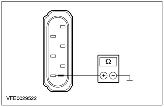
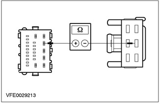
3 Measure the resistance between pin 6 of connector C476, left tail light assembly, circuit 31-LF23 (black), from the wiring side, and "ground". |
|
• Is the resistance less than 2 ohms? |
|
|
→ Yes |
|
|
INSTALL a new common electronics module (GEM). CHECK the system is working properly. |
|
|
→ No |
|
|
REPAIR open circuit 31-DA18 using the wiring diagrams (black) between splice S184 and earth point G46. CHECK the system is working properly. |
|
|
AD9: REAR TURN SIGNALS GROUND ELECTRICAL CIRCUIT CHECK |
|
|
1 Enter the OFF position. |
|
|
2 Disconnect C461 left rear turn signal. |
|

|
3 Measure the resistance between pin 2 of connector C461 left rear turn signal circuit 31-LG12 (black), from the wiring side, and "ground". |
|
• Is the resistance less than 2 ohms? |
|
|
→ Yes |
|
|
INSTALL a new common electronics module (GEM). CHECK the system is working properly. |
|
|
→ No |
|
|
REPAIR open circuit 31-DA18 using the wiring diagrams (black) between splice S184 and earth point G46. CHECK the system is working properly. |
|
|
AD10: TEST LIGHT ASSEMBLY GROUND CIRCUIT |
|
|
1 Enter the OFF position. |
|
|
2 Disconnect the C474 left rear light assembly. |
|

|
3 Measure the resistance between pin 6 of connector C474, left tail light assembly, circuit 31-LF23A (black), from the wiring side, and "ground". |
|
• Is the resistance less than 2 ohms? |
|
|
→ Yes |
|
|
INSTALL a new common electronics module (GEM). CHECK the system is working properly. |
|
|
→ No |
|
|
LOCATE and REPAIR open circuit 31-DA18 using the wiring diagrams (black) between splice S184 and earth point G46. CHECK the system is working properly. |
|
|
AD11: LEFT FRONT TURN SIGNAL GROUND CIRCUIT INSPECTION |
|
|
1 Enter the OFF position. |
|
|
2 Disconnect the left headlight C836. |
|
|
3 Measure the resistance between pin 6 of connector C836, left headlight, circuit 31-LE31 (black), from the wiring side, and "ground". |
|
• Is the resistance less than 2 ohms? |
|
|
→ Yes |
|
|
Go to AD12 |
|
|
→ No |
|
|
LOCATE and REPAIR open circuit 31-DA3 using the wiring diagrams (black) between splice S121 and earth point G37. CHECK the system is working properly. |
|
|
AD12: CHECK CONTROL CIRCUIT TO LEFT FRONT TURN SIGNALS FOR OPEN |
|
|
1 Disconnect C103 General Electronics Module (GEM). |
|
|
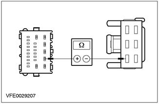
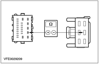
2 Measure the resistance between pin 4 of connector C103 of the GEM (GEM), electrical circuit 49S-LG3 (blue), on the wiring side, and pin 3 of connector C836 of the left headlight, circuit 49S-LG11 (orange-blue), from the side of the electrical wiring. |
|
• Is the resistance less than 2 ohms? |
|
|
→ Yes |
|
|
INSTALL a new common electronics module (GEM). CHECK the system is working properly. |
|
|
→ No |
|
|
LOCATE and REPAIR open circuit 49S-LG3 using the wiring diagrams (blue) between common electronic module (GEM) and splice S104. CHECK the system is working properly. |
|
|
AD13: LEFT SIDE TURN SIGNAL GROUND CIRCUIT CHECK |
|
|
1 Enter the OFF position. |
|
|
2 Disconnect C753 left side turn signal. |
|
|
3 Measure the resistance between pin 1 of connector C753 left side turn signal circuit 31-LG13 (black), from the wiring side, and "ground". |
|
• Is the resistance less than 2 ohms? |
|
|
→ Yes |
|
|
Go to AD14 |
|
|
→ No |
|
|
LOCATE and REPAIR open circuit 31-LG13 using the wiring diagrams (black) between side turn signal and splice S121. CHECK the system is working properly. |
|
|
AD14: LEFT SIDE TURN SIGNAL POWER CIRCUIT CHECK |
|
|
1 Drive the ON position. |
|
|
2 Turn on the left TURN SIGNAL. |
|
|
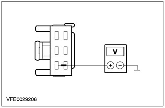
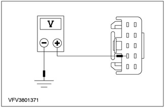
3 Measure the voltage between pin 2 of connector C753 left side turn signal circuit 49S-LG13 (red-blue), from the wiring side, and "ground". |
|
• Is fluctuating battery voltage being detected? |
|
|
→ Yes |
|
|
CHECK the side turn signal, INSTALL a new one if necessary. CHECK the system is working properly. |
|
|
→ No |
|
|
LOCATE and REPAIR open circuit 49S-LG13 using the wiring diagrams (red-blue) between the side turn signal and splice S104. Check the condition of the bypass in the cylinder |
|
|
AD15: RIGHT SIDE TURN SIGNAL GROUND CIRCUIT CHECK |
|
|
1 Enter the OFF position. |
|
|
2 Disconnect the C754 right side turn signal. |
|

|
3 Measure the resistance between pin 1 of right side turn signal connector C754, circuit 31-LG20 (black), from the wiring side, and "ground". |
|
• Is the resistance less than 2 ohms? |
|
|
→ Yes |
|
|
Go to AD16 |
|
|
→ No |
|
|
LOCATE and REPAIR open circuit 31-LG20 using the wiring diagrams (black) and 31-DA6 (black) between the side turn signal and earth point G24. CHECK the system is working properly. |
|
|
AD16: RIGHT SIDE TURN SIGNAL POWER CIRCUIT CHECK |
|
|
1 Drive the ON position. |
|
|
2 Turn on the right TURN SIGNAL. |
|
|
3 Measure the voltage between pin 2 of connector C754, right side turn signal, circuit 49S-LG20 (white-blue), from the wiring side, and "ground". |
|
• Is fluctuating battery voltage being detected? |
|
|
→ Yes |
|
|
CHECK the side turn signal, INSTALL a new one if necessary. CHECK the system is working properly. |
|
|
→ No |
|
|
LOCATE and REPAIR open circuit 49S-LG20 using the wiring diagrams (white-blue) between the side direction indicator and the common electronic module (GEM). CHECK the system is working properly. |
|
|
AD17: LEFT HEADLIGHT GROUND CIRCUIT CHECK |
|
|
1 Enter the OFF position. |
|
|
2 Disconnect the left headlight C836. |
|

|
3 Measure the resistance between pin 6 of connector C836, left headlight, circuit 31-LE31 (black), from the wiring side, and "ground". |
|
• Is the resistance less than 2 ohms? |
|
|
→ Yes |
|
|
Go to AD18 |
|
|
→ No |
|
|
LOCATE and REPAIR open circuit 31-LE31 using the wiring diagrams (black) between headlight and splice S121. CHECK the system is working properly. |
|
|
AD18: LEFT HEADLIGHT POWER CIRCUIT CHECK |
|
|
1 Drive the ON position. |
|
|
2 Turn on the left TURN SIGNAL. |
|
|
3 Measure the voltage between pin 3 of connector C836, left headlight, circuit 49S-LG11 (orange-blue), from the wiring side, and "ground". |
|
• Is fluctuating battery voltage being detected? |
|
|
→ Yes |
|
|
CHECK the headlight, INSTALL a new one if necessary. CHECK the system is working properly. |
|
|
→ No |
|
|
LOCATE and REPAIR open circuit 49S-LG11 using the wiring diagrams (orange-blue) between headlight and splice S104. CHECK the system is working properly. |
|
|
AD19: RIGHT HEADLIGHT GROUND CIRCUIT CHECK |
|
|
1 Enter the OFF position. |
|
|
2 Disconnect the C837 right headlight. |
|
|
3 Measure the resistance between pin 6 of connector C837 of the right headlight, circuit 31-LE30 (black), from the wiring side, and "ground". |
|
• Is the resistance less than 2 ohms? |
|
|
→ Yes |
|
|
Go to AD20 |
|
|
→ No |
|
|
LOCATE and REPAIR open circuits using the wiring diagrams 31-LE30 (black) and 31-DA4 (black) between headlight and earth point G56. CHECK the system is working properly. |
|
|
AD20: RIGHT HEADLIGHT POWER CIRCUIT CHECK |
|
|
1 Drive the ON position. |
|
|
2 Turn on the right TURN SIGNAL. |
|

|
3 Measure the voltage between pin 3 of connector C837 of the right headlight, circuit 49S-LG18 (blue), from the wiring side, and "ground". |
|
• Is fluctuating battery voltage being detected? |
|
|
→ Yes |
|
|
CHECK the headlight, INSTALL a new one if necessary. CHECK the system is working properly. |
|
|
→ No |
|
|
LOCATE and REPAIR open circuit 49S-LG18 using the wiring diagrams (blue) between the headlight and the common electronic module (GEM). CHECK the system is working properly. |
|
|
AD21: LEFT REAR LIGHT ASSEMBLY GROUND CIRCUIT CHECK |
|
|
1 Enter the OFF position. |
|
|
2 Disconnect the C476 left rear light assembly. |
|
|
3 Measure the resistance between pin 6 of connector C476, left tail light assembly, circuit 31-LF23 (black), from the wiring side, and "ground". |
|
• Is the resistance less than 2 ohms? |
|
|
→ Yes |
|
|
Go to AD22 |
|
|
→ No |
|
|
Using the wiring diagrams, LOCATE and REPAIR open circuit 31-LF23 (black) between tail light assembly and splice S184. CHECK the system is working properly. |
|
|
AD22: LEFT REAR LIGHT ASSEMBLY ELECTRICAL CHECK |
|
|
1 Drive the ON position. |
|
|
2 Turn on the left TURN SIGNAL. |
|
|
3 Measure the voltage between pin 3 of connector C476, left tail light assembly, circuit 49S-LG12 (blue), from the wiring side, and "ground". |
|
• Is fluctuating battery voltage being detected? |
|
|
→ Yes |
|
|
CHECK the tail light assembly, INSTALL a new one if necessary. CHECK the system is working properly. |
|
|
→ No |
|
|
Go to AD23 |
|
|
AD23: 49S-LG12 ELECTRICAL CONTROL CIRCUIT CHECK (BLUE) FOR A BREAK |
|
|
1 Enter the OFF position. |
|
|
2 Disconnect C101 common electronic module (GEM). |
|
|
3 Measure the resistance between pin 2 of connector C101 of the GEM (GEM), electrical circuit 49S-LG12 (blue), on the wiring side, and pin 3 of connector C476, rear light assembly, circuit 49S-LG12 (blue), from the side of the electrical wiring. |
|
• Is the resistance less than 2 ohms? |
|
|
→ Yes |
|
|
INSTALL a new common electronics module (GEM). CHECK the system is working properly. |
|
|
→ No |
|
|
LOCATE and REPAIR open circuit 49S-LG12 using the wiring diagrams (blue) between rear light assembly and common electronic module (GEM). CHECK the system is working properly. |
|
|
AD24: LEFT REAR TURN SIGNAL GROUND CIRCUIT INSPECTION |
|
|
1 Enter the OFF position. |
|
|
2 Disconnect C461 left rear turn signal. |
|
|
3 Measure the resistance between pin 2 of connector C461 left rear turn signal circuit 31-LG12 (black), from the wiring side, and "ground". |
|
• Is the resistance less than 2 ohms? |
|
|
→ Yes |
|
|
Go to AD25 |
|
|
→ No |
|
|
LOCATE and REPAIR open circuit 31-LG12 using the wiring diagrams (black) between the rear turn signal and splice S184. CHECK the system is working properly. |
|
|
AD25: CHECKING THE ELECTRICAL POWER CIRCUIT OF THE LEFT REAR TURN SIGNAL |
|
|
1 Drive the ON position. |
|
|
2 Turn on the left TURN SIGNAL. |
|

|
3 Measure the voltage between pin 1 of connector C461 left rear turn signal circuit 49S-LG12 (blue), from the wiring side, and "ground". |
|
• Is fluctuating battery voltage being detected? |
|
|
→ Yes |
|
|
CHECK the rear turn signal, INSTALL a new one if necessary. CHECK the system is working properly. |
|
|
→ No |
|
|
Go to AD26 |
|
|
AD26: 49S-LG12 ELECTRICAL CONTROL CIRCUIT CHECK (BLUE) FOR A BREAK |
|
|
1 Enter the OFF position. |
|
|
2 Disconnect C101 common electronic module (GEM). |
|
|
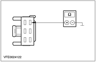
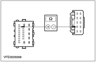
3 Measure the resistance between pin 2 of connector C101 of the GEM (GEM), electrical circuit 49S-LG12 (blue), on the wiring side, and pin 1 of connector C461 of the rear turn signal, circuit 49S-LG12 (blue), from the side of the electrical wiring. |
|
• Is the resistance less than 2 ohms? |
|
|
→ Yes |
|
|
INSTALL a new common electronics module (GEM). CHECK the system is working properly. |
|
|
→ No |
|
|
LOCATE and REPAIR open circuit 49S-LG12 using the wiring diagrams (blue) between the rear turn signal and the common electronic module (GEM). CHECK the system is working properly. |
|
|
AD27: LEFT REAR LIGHT ASSEMBLY GROUND ELECTRICAL CHECK |
|
|
1 Enter the OFF position. |
|
|
2 Disconnect the C474 left rear light assembly. |
|
|
3 Measure the resistance between pin 6 of connector C474, left tail light assembly, circuit 31-LF23A (black), from the wiring side, and "ground". |
|
• Is the resistance less than 2 ohms? |
|
|
→ Yes |
|
|
Go to AD28 |
|
|
→ No |
|
|
Using the wiring diagrams, LOCATE and REPAIR open circuit 31-LF23A (black) between tail light assembly and splice S184. CHECK the system is working properly. |
|
|
AD28: LEFT REAR LIGHT ASSEMBLY ELECTRICAL CHECK |
|
|
1 Drive the ON position. |
|
|
2 Turn on the left TURN SIGNAL. |
|

|
3 Measure the voltage between pin 5 of connector C474, left tail light assembly, circuit 49S-LG12 (blue), from the wiring side, and "ground". |
|
• Is fluctuating battery voltage being detected? |
|
|
→ Yes |
|
|
CHECK the tail light assembly, INSTALL a new one if necessary. CHECK the system is working properly. |
|
|
→ No |
|
|
Go to AD29 |
|
|
AD29: 49S-LG12 ELECTRICAL CONTROL CIRCUIT CHECK (BLUE) FOR A BREAK |
|
|
1 Enter the OFF position. |
|
|
2 Disconnect C101 common electronic module (GEM). |
|
|
3 Measure the resistance between pin 2 of connector C101 of the GEM (GEM), electrical circuit 49S-LG12 (blue), on the wiring side, and pin 5 of connector C474, rear light assembly, circuit 49S-LG12 (blue), from the side of the electrical wiring. |
|
• Is the resistance less than 2 ohms? |
|
|
→ Yes |
|
|
INSTALL a new common electronics module (GEM). CHECK the system is working properly. |
|
|
→ No |
|
|
LOCATE and REPAIR open circuit 49S-LG12 using the wiring diagrams (blue) between rear light assembly and common electronic module (GEM). CHECK the system is working properly. |
|
|
AD30: RIGHT TAIL LAMP ASSEMBLY GROUND ELECTRICAL CHECK |
|
|
1 Enter the OFF position. |
|
|
2 Disconnect the C477 right tail light assembly. |
|
|
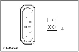
3 Measure the resistance between pin 4 of connector C477, right tail light assembly, circuit 31-LF24 (black), from the wiring side, and "ground". |
|
• Is the resistance less than 2 ohms? |
|
|
→ Yes |
|
|
Go to AD31 |
|
|
→ No |
|
|
LOCATE and REPAIR open circuit 31-LF24 using the wiring diagrams (black) between tail light assembly and splice S184. CHECK the system is working properly. |
|
|
AD31: RIGHT TAIL LIGHT ASSEMBLY ELECTRICAL CHECK |
|
|
1 Drive the ON position. |
|
|
2 Turn on the right TURN SIGNAL. |
|
|
3 Measure the voltage between pin 1 of connector C477, right tail light assembly, circuit 49S-LG19 (red-blue), from the wiring side, and "ground". |
|
• Is fluctuating battery voltage being detected? |
|
|
→ Yes |
|
|
CHECK the tail light assembly, INSTALL a new one if necessary. CHECK the system is working properly. |
|
|
→ No |
|
|
Go to AD32 |
|
|
AD32: 49S-LG19 ELECTRICAL CONTROL CIRCUIT CHECK (RED-BLUE) FOR A BREAK |
|
|
1 Enter the OFF position. |
|
|
2 Disconnect C102 general electronic module (GEM). |
|
|
3 Measure the resistance between pin 4 of connector C102 of the common electronic module (GEM), electrical circuit 49S-LG19 (red-blue), on the wiring side, and pin 1 of connector C477 of the right rear light assembly, circuit 49S-LG19 (red-blue), from the side of the electrical wiring. |
|
• Is the resistance less than 2 ohms? |
|
|
→ Yes |
|
|
INSTALL a new common electronics module (GEM). CHECK the system is working properly. |
|
|
→ No |
|
|
LOCATE and REPAIR open circuit 49S-LG19 using the wiring diagrams (red-blue) between rear light assembly and common electronic module (GEM). CHECK the system is working properly. |
|
|
AD33: RIGHT REAR TURN SIGNAL GROUND CIRCUIT CHECK |
|
|
1 Enter the OFF position. |
|
|
2 Disconnect C462 right rear turn signal. |
|
|
3 Measure the resistance between pin 2 of connector C462, right rear turn signal, circuit 31-LG19 (black), from the wiring side, and "ground". |
|
• Is the resistance less than 2 ohms? |
|
|
→ Yes |
|
|
Go to AD34 |
|
|
→ No |
|
|
LOCATE and REPAIR open circuit 31-LG19 using the wiring diagrams (black) between the rear turn signal and splice S184. CHECK the system is working properly. |
|
|
AD34: RIGHT REAR TURN SIGNAL POWER CIRCUIT CHECK |
|
|
1 Drive the ON position. |
|
|
2 Turn on the right TURN SIGNAL. |
|
|
3 Measure the voltage between pin 1 of connector C462, right rear turn signal, circuit 49S-LG19 (red-blue), from the wiring side, and "ground". |
|
• Is fluctuating battery voltage being detected? |
|
|
→ Yes |
|
|
CHECK the rear turn signal, INSTALL a new one if necessary. CHECK the system is working properly. |
|
|
→ No |
|
|
Go to AD35 |
|
|
AD35: 49S-LG19 ELECTRICAL CONTROL CIRCUIT CHECK (RED-BLUE) FOR A BREAK |
|
|
1 Enter the OFF position. |
|
|
2 Disconnect C102 general electronic module (GEM). |
|
|
3 Measure the resistance between pin 4 of connector C102 of the common electronic module (GEM), electrical circuit 49S-LG19 (red-blue), on the wiring side, and pin 1 of connector C462 of the rear turn signal, circuit 49S-LG19 (red-blue), from the side of the electrical wiring. |
|
• Is the resistance less than 2 ohms? |
|
|
→ Yes |
|
|
INSTALL a new common electronics module (GEM). CHECK the system is working properly. |
|
|
→ No |
|
|
LOCATE and REPAIR open circuit 49S-LG19 using the wiring diagrams (red-blue) between the rear turn signal and the common electronic module (GEM). CHECK the system is working properly. |
|
|
AD36: RIGHT TAIL LIGHT ASSEMBLY GROUND ELECTRICAL CHECK |
|
|
1 Enter the OFF position. |
|
|
2 Disconnect the C475 right tail light assembly. |
|
|
3 Measure the resistance between pin 6 of connector C475, right tail light assembly, circuit 31-LF24A (black), from the wiring side, and "ground". |
|
• Is the resistance less than 2 ohms? |
|
|
→ Yes |
|
|
Go to AD37 |
|
|
→ No |
|
|
LOCATE and REPAIR open circuit 31-LF24A using the wiring diagrams (black) between tail light assembly and splice S184. CHECK the system is working properly. |
|
|
AD37: RIGHT TAIL LIGHT ASSEMBLY ELECTRICAL CHECK |
|
|
1 Drive the ON position. |
|
|
2 Turn on the right TURN SIGNAL. |
|
|
3 Measure the voltage between pin 5 of connector C475, right tail light assembly, circuit 49S-LG19 (red-blue), from the wiring side, and "ground". |
|
• Is fluctuating battery voltage being detected? |
|
|
→ Yes |
|
|
CHECK the tail light assembly, INSTALL a new one if necessary. CHECK the system is working properly. |
|
|
→ No |
|
|
Go to AD38 |
|
|
AD38: 49S-LG19 ELECTRICAL CONTROL CIRCUIT CHECK (RED-BLUE) FOR A BREAK |
|
|
1 Enter the OFF position. |
|
|
2 Disconnect C102 general electronic module (GEM). |
|
|
3 Measure the resistance between pin 4 of connector C102 of the common electronic module (GEM), electrical circuit 49S-LG19 (red-blue), on the wiring side, and pin 5 of connector C475, rear light assembly, circuit 49S-LG19 (red-blue), from the side of the electrical wiring. |
|
• Is the resistance less than 2 ohms? |
|
|
→ Yes |
|
|
INSTALL a new common electronics module (GEM). CHECK the system is working properly. |
|
|
→ No |
|
|
LOCATE and REPAIR open circuit 49S-LG19 using the wiring diagrams (red-blue) between rear light assembly and common electronic module (GEM). CHECK the system is working properly. |
|
PINPOINT TEST AE: TURN SIGNALS WORK CORRECTLY BUT NO BEEP.
|
STATES |
DETAILS/RESULTS/ACTIONS |
|
AE1: TURN SIGNAL SWITCH GROUND ELECTRICAL INSPECTION |
|
|
1 Enter the OFF position. |
|
|
2 Disconnect the C459 turn signal switch. |
|
|
3 Measure the resistance between pin 5 of connector C459 turn signal switch circuit 91-LG43 (black and white), from the wiring side, and "ground". |
|
• Is the resistance less than 2 ohms? |
|
|
→ Yes |
|
|
Go to AE2 |
|
|
→ No |
|
|
LOCATE and REPAIR open circuit 91-LG43 using the wiring diagrams (black), between the turn signal switch and splice S12. CHECK the system is working properly. |
|
|
AE2: TURN SIGNAL SWITCH TEST |
|
|
1 Install a jumper wire in connector C459 of the turn signal switch, between pin 1, circuit 91S-LG1 (black and yellow), and pin 2, electrical circuit 91-LG27 (black and green), from the side of the electrical wiring. |
|
2 Drive the ON position. |
|
|
3 Measure the voltage between pin 4 of connector C459 turn signal switch circuit 29S-LG43 (orange white), from the wiring side, and "ground". |
|
• Is fluctuating battery voltage being detected? |
|
|
→ Yes |
|
|
CHECK the direction indicator switch, proceeding in accordance with the chapter "Checking the elements" attached to the wiring diagrams; INSTALL a new one if necessary. CHECK the system is working properly. |
|
|
→ No |
|
|
Go to AE3 |
|
|
AE3: 29S-LG43 ELECTRICAL CONTROL CIRCUIT CHECK (ORANGE-WHITE) FOR A BREAK |
|
|
1 Enter the OFF position. |
|
|
2 Disconnect C105 common electronic module (GEM). |
|
|
3 Measure the resistance between pin 22 of connector C105 of the GEM (GEM), electrical circuit 29S-LG43 (orange white), on the wiring side, and pin 4 of connector C459 of the turn signal switch, circuit 29S-LG43 (orange white), from the side of the electrical wiring,. |
|
• Is the resistance less than 2 ohms? |
|
|
→ Yes |
|
|
CHECK the common electronic module (GEM), if necessary, INSTALL a new one. CHECK the system is working properly. |
|
|
→ No |
|
|
Using the wiring diagrams, LOCATE and REPAIR open circuit 29S-LG43 (orange white), between common electronic module (GEM) and turn signal switch. CHECK the system is working properly. |
|
Visitor comments