


Special tool
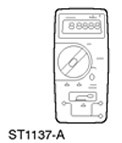 | Digital Multimeter 105-R0051 or equivalent |
 | Electrical Probe Kit 29-011A |
Inspection and verification
1. Check the customer complaint.
2. Perform a visual inspection for obvious signs of mechanical or electrical damage.
Visual inspection table
Electrical factors:
- Fuse Box(s)
- Lamp(s)
- Electrical connector(s)
- Wiring harness
3. If an obvious cause for the problem you have identified or the customer has described is found, correct it (if possible) before proceeding with further actions.
4. If the problem is not visually obvious, check the symptom and refer to the Symptom Table.
Table of signs of malfunction
|
State |
Possible Causes |
Action |
|
Direction indicators always off/always on |
•Fuse(s) •Electrical circuit(s) •Direction indicator switch. •Hazard warning light switch. •General Electronic Module (GEM) |
• Proceed to PINPOINT TEST AB |
|
•The hazard warning lights are not working |
•Chain(s) •Hazard warning light switch. •General Electronic Module (GEM) |
• Proceed to AC PINPOINT TEST |
|
•One or more direction indicators are always on/always off |
•Electrical circuit(s) •Hazard warning light switch. •Front direction indicator •Side direction indicator •Rear direction indicator (4-door version) •Assembled rear light ((3/5-door version), "station wagon") |
• Proceed to PINPOINT TEST AD |
|
•The turn signals work correctly, but there is no sound signal |
•Electrical circuit(s) •Direction indicator switch. |
• Proceed to PINPOINT TEST AE |
This publication was borrowed from the website: FordBook