|
STATES |
DETAILS/RESULTS/ACTIONS |
|
R1: CHECK FUSE F54 |
|
|
1 CHECK F54. |
|
|
• Is the fuse good? |
|
|
→ Yes |
|
|
Go to R2 |
|
|
→ No |
|
|
REPLACE fuse F54. If fuse F54 fails again, FIND and REPAIR the short circuit using the wiring diagrams. CHECK the system is working properly. |
|
|
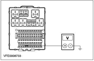
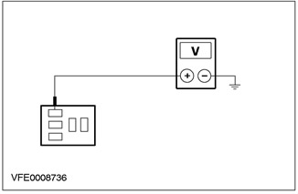
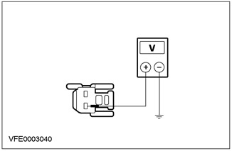
R2: CHECK THE VOLTAGE IN FUSE AREA F54 |
|
|
1 Drive the ON position. |
|
|
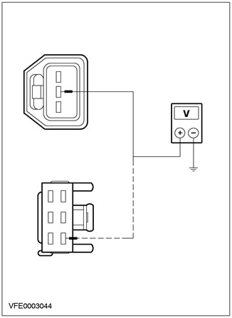
2 Measure the voltage between fuse F54 and "weight". |
|
• Does the meter show battery voltage? |
|
|
→ Yes |
|
|
Go to R3 |
|
|
→ No |
|
|
Go to R9 |
|
|
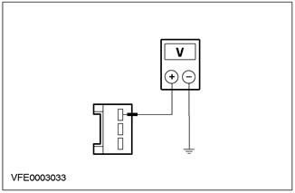
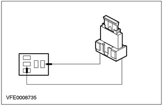
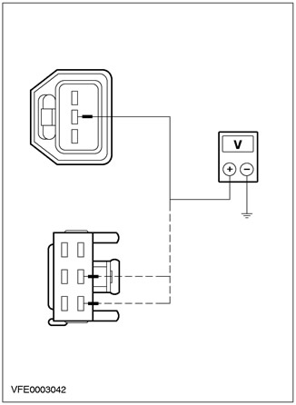
R3: CHECK STOP LIGHT SWITCH VOLTAGE |
|
|
1 Disconnect C444. |
|
|
2 Drive the ON position. |
|
|
3 Measure the voltage at pin 3 of C444,. |
|
• Does the meter show battery voltage? |
|
|
→ Yes |
|
|
Go to R4 |
|
|
→ No |
|
|
REPAIR circuit 15-LG23. CHECK the system is working properly. |
|
|
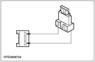
R4: CHECK STOP LIGHT SWITCH |
|
|
1 Disconnect C444. |
|
|
2 Drive the ON position. |
|
|
3 Use a suitable wire as a jumper between pins 3 and 1 of connector C444. |
|
• Do the brake lights come on? |
|
|
→ Yes |
|
|
REPLACE brake light switch. CHECK the system is working properly. |
|
|
→ No |
|
|
Vehicles with Electronic Stability Program (ESP): Go to R5 |
|
|
Vehicles without Electronic Stability Program (ESP): REPAIR circuit 15S-LG14A (green-red) or 15S-LG14B (green-red). CHECK the system is working properly. |
|
|
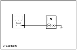
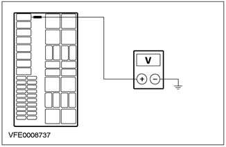
R5: INSPECT STOP LIGHT RELAY |
|
|
1 Detach the CBJB. |
|
|
2 Drive the ON position. |
|
|
3 Depress the brake pedal. |
|
|
4 Check the voltage on pin 3 of the C1014 BJB. |
|
• Does the meter show battery voltage? |
|
|
→ Yes |
|
|
Go to R6 |
|
|
→ No |
|
|
REPAIR circuit 15S-LG14B, 15S-CF58, or 15S-CF58A. CHECK the system is working properly. |
|
|
R6: INSPECT STOP LIGHT RELAY |
|
|
1 Detach C1014 BJB. |
|
|
2 Drive the ON position. |
|
|
3 Depress the brake pedal. |
|
|
4 Use a suitable wire as a jumper between pins 3 and 4 of the C1014 BJB connector. |
|
• Do the brake lights come on? |
|
|
→ Yes |
|
|
Go to R7 |
|
|
→ No |
|
|
REPAIR circuit 15S-LG14A. CHECK the system is working properly. |
|
|
R7: INSPECT STOP LIGHT RELAY |
|
|
1 Detach C1014 BJB. |
|
|
2 Drive the ON position. |
|
|
3 Check the voltage on pin 1 of the C1014 BJB. |
|
• Does the meter show battery voltage? |
|
|
→ Yes |
|
|
Go to R8 |
|
|
→ No |
|
|
REPAIR circuit 15-CF58. CHECK the system is working properly. |
|
|
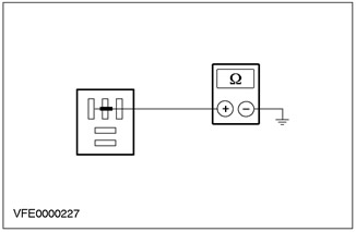
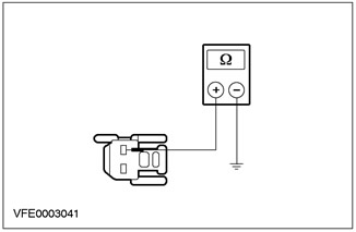
R8: INSPECT STOP LIGHT RELAY |
|
|
1 Detach C1014 BJB. |
|
|
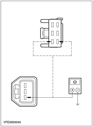
2 Using an ohmmeter, measure the resistance between pin 2 of the C1014 BJB connector and "weight". |
|
• Is the measured resistance less than 2 ohms? |
|
|
→ Yes |
|
|
REPLACE brake light relay. CHECK the system is working properly. |
|
|
→ No |
|
|
REPAIR circuit 31S-CF71 if necessary REPLACE electronic stability program module (ESP). CHECK the system is working properly. |
|
|
R9: CHECK POWER SUPPLY |
|
|
1 Disconnect Fuse F1. |
|
|
2 CHECK Fuse F1. |
|
|
• Is fuse F1 in BJB OK? |
|
|
→ Yes |
|
|
Go to R10 |
|
|
→ No |
|
|
REPLACE fuse F1. If fuse F1 fails again, FIND and REPAIR the short circuit using the wiring diagrams. CHECK the system is working properly. |
|
|
R10: CHECK POWER SUPPLY |
|
|
1 Drive the ON position. |
|
|
2 Measure the voltage at fuse F1. |
|
• Does the meter show battery voltage? |
|
|
→ Yes |
|
|
REPAIR circuit 15-DA3 if necessary REPLACE CJB. CHECK the system is working properly. |
|
|
→ No |
|
|
REPAIR circuit 15-DC1 if necessary REPLACE ignition relay. CHECK the system is working properly. |
|
PINPOINT TEST S: ONE OR MORE STOP LIGHTS DO NOT WORK
|
STATES |
DETAILS/RESULTS/ACTIONS |
|
S1: CHECK OPTIONAL STOP LIGHT |
|
|
1 Drive the ON position. |
|
|
2 Depress the brake pedal. |
|
|
• Does the auxiliary brake light come on? |
|
|
→ Yes |
|
|
Go to S4 |
|
|
→ No |
|
|
Go to S2 |
|
|
S2: INSPECT ELECTRICAL CIRCUIT 15S-LG6 |
|
|
1 Enter the OFF position. |
|
|
2 Disconnect C107 additional brake lights. |
|
|
3 Drive the ON position. |
|
|
4 Depress the brake pedal. |
|
|
5 Check voltage between C107 accessory brake light connector pin 1, circuit 15S-LG6 (green-yellow), from the wiring side, and "weight". |
|
• Does the meter show battery voltage? |
|
|
→ Yes |
|
|
Go to S3 |
|
|
→ No |
|
|
REPAIR circuit 15S-LG6. CHECK the system is working properly. |
|
|
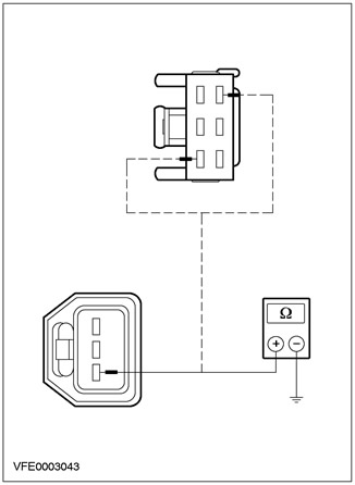
S3: INSPECT 31-LG6 GAS ELECTRICAL CIRCUIT |
|
|
1 Enter the OFF position. |
|
|
2 Check resistance between C107 auxiliary brake light connector pin 2, circuit 31-LG6 (black), from the wiring side, and "weight". |
|
• Is the resistance less than 2 ohms? |
|
|
→ Yes |
|
|
After checking the bulb, REPLACE the auxiliary brake light. CHECK the system is working properly. |
|
|
→ No |
|
|
REPAIR 31-LG6 fouling circuit. CHECK the system is working properly. |
|
|
S4: CHECK THE STOP LIGHTS |
|
|
1 Check the operation of the brake lights. |
|
|
• Are both brake lights not working? |
|
|
→ Yes |
|
|
REPAIR circuit 15S-LG14 (green-red), and/or REPAIR solder points S154 or S212. CHECK the system is working properly. |
|
|
→ No |
|
|
Right brake light not working: Go to S5 |
|
|
Left brake light not working: Go to S7 |
|
|
S5: CHECK ELECTRICAL CIRCUIT 15S-LG21 |
|
|
1 Enter the OFF position. |
|
|
2 Disconnect the C473, C475 and/or C477 of the right rear light assembly. |
|
|
3 Drive the ON position. |
|
|
4 Check the voltage between the right tail lamp assembly, circuit 15S-LG21 (green-black), from the wiring side, and "weight". - 3-/5-door options: pin 2 C473 - 4-door variant: pin 2 C477 - "station wagon": pin 1 C475 |
|
• Does the meter show battery voltage? |
|
|
→ Yes |
|
|
Go to S6 |
|
|
→ No |
|
|
REPAIR circuit 15S-LG21. CHECK the system is working properly. |
|
|
S6: CHECK 31-LF24 / 31-LF4 ELECTRICAL GROUND CIRCUIT |
|
|
1 Enter the OFF position. |
|
|
2 Measure the resistance between the right tail light assembly, circuit 31-LF24 (black), 31-LF4, wiring side, and "weight". - 3-/5-door options: pin 3 C473 - 4-door variant: pin 4 C477 - "station wagon": pin 3 C475 |
|
• Is the resistance less than 2 ohms? |
|
|
→ Yes |
|
|
After checking the bulb, REPLACE the right rear light assembly. CHECK the system is working properly. |
|
|
→ No |
|
|
REPAIR the 31-LF24 / 31-LF4 ground circuit. CHECK the system is working properly. |
|
|
S7: CHECK ELECTRICAL CIRCUIT 15S-LG14A |
|
|
1 Enter the OFF position. |
|
|
2 Disconnect the C472, C474 and/or C476 tail light assembly. |
|
|
3 Drive the ON position. |
|
|
4 Check the voltage between the left rear light unit, circuit 15S-LG14A (green-red), from the wiring side, and "weight". - 3-/5-door options: pin 2 C472 - 4-door variant: pin 1 C476 - "station wagon": pin 1 C474 |
|
• Does the meter show battery voltage? |
|
|
→ Yes |
|
|
Go to S6 |
|
|
→ No |
|
|
REPAIR circuit 15S-LG14A. CHECK the system is working properly. |
|
|
S8: CHECK 31-LF23 / 31-DA18 GROUND CIRCUIT |
|
|
1 Enter the OFF position. |
|
|
2 Measure the resistance between the left tail light assembly, circuit 31-LF23 (black) / 31-DA18 (black), from the wiring side, and "weight". - 3-/5-door options: pin 3 C472 - 4-door variant: pin 6 C476 - "station wagon": pin 3 C474 |
|
• Is the resistance less than 2 ohms? |
|
|
→ Yes |
|
|
After checking the bulb, REPLACE the left rear light assembly. CHECK the system is working properly. |
|
|
→ No |
|
|
REPAIR the ground circuit 31-LF23 / 31-DA18 CHECK the system is working properly. |
|
PINPOINT TEST: STOP LIGHTS PERMANENTLY ON
|
STATES |
DETAILS/RESULTS/ACTIONS |
|
T1: CHECK ELECTRICAL CIRCUIT (AND) |
|
|
1 Disconnect Connector C51. |
|
|
2 Drive the ON position. |
|
|
• Are the brake lights on all the time? |
|
|
→ Yes |
|
|
REPAIR circuit 15S-LG21 (green-black), 15S-LG14A (green-red), 15S-LG14 (green-red) or 15S-LG6 (green-yellow). CHECK the system is working properly. |
|
|
→ No |
|
|
Go to T2 |
|
|
T2: CHECK STOP LIGHT SWITCH |
|
|
1 Disconnect Connector C444. |
|
|
2 Drive the ON position. |
|
|
• Do the brake lights come on? |
|
|
→ Yes |
|
|
Vehicles without Electronic Stability Program: Go to T3 |
|
|
Vehicles with Electronic Stability Program: Go to T6 |
|
|
→ No |
|
|
REPLACE brake light switch. CHECK the system is working properly. |
|
|
T3: CHECK MODULES |
|
|
1 Disconnect the C385 ABS control module. |
|
|
2 Disconnect the C415 powertrain control module. |
|
|
3 Disconnect the C831 speed control module. |
|
|
• Are the brake lights on all the time? |
|
|
→ Yes |
|
|
REPAIR circuits 15S-CF58, 15S-LG14B, 15S-LG14A, 15S-RN2, 15S-RE13, or 15S-PG17. CHECK the system is working properly. |
|
|
→ No |
|
|
Go to T4 |
|
|
T4: CHECK ABS CONTROL MODULE |
|
|
1 Connect the ABS Control Module. |
|
|
2 Drive the ON position. |
|
|
• Are the brake lights on all the time? |
|
|
→ Yes |
|
|
REPLACE ABS control module. CHECK the system is working properly. |
|
|
→ No |
|
|
Go to T5 |
|
|
T5: INSPECT POWERTRAIN CONTROL MODULE (PCM) |
|
|
1 Connect Powertrain Control Module (PCM). |
|
|
2 Drive the ON position. |
|
|
• Are the brake lights on all the time? |
|
|
→ Yes |
|
|
REPLACE the powertrain control module (PCM) CHECK the system is working properly. |
|
|
→ No |
|
|
REPLACE speed control module. CHECK the system is working properly. |
|
|
T6: CHECK ELECTRICAL CIRCUIT 15S-LG14A |
|
|
1 Detach C1014 BJB. |
|
|
2 Drive the ON position. |
|
|
• Are the brake lights on all the time? |
|
|
→ Yes |
|
|
REPAIR circuit 15S-LG14A to C51. CHECK the system is working properly. |
|
|
→ No |
|
|
Go to T7 |
|
|
T7: CHECK MODULES |
|
|
1 Disconnect the C830 of the Electronic Stability Program module. |
|
|
2 Disconnect the C415 powertrain control module. |
|
|
3 Disconnect the C831 speed control module. |
|
|
4 Drive the ON position. |
|
|
• Are the brake lights on all the time? |
|
|
→ Yes |
|
|
REPAIR circuit 15S-PG7, 15S-PG17, 15S-RE13, 15S-RN2, 15S-CF58, or 15S-CF58A. CHECK the system is working properly. |
|
|
→ No |
|
|
Move to T8 |
|
|
T8: CHECK E-STABILITY PROGRAM MODULE (ESP) |
|
|
1 Connect the Electronic Stability Program Module (ESP). |
|
|
2 Drive the ON position. |
|
|
• Are the brake lights on all the time? |
|
|
→ Yes |
|
|
REPLACE Electronic Stability Program module (ESP). CHECK the system is working properly. |
|
|
→ No |
|
|
Go to T5 |
|
Item checks
Brake light relay
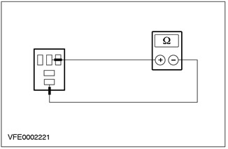
1. Check normally closed contact.
- Check the resistance between pin 3 and pin 4.
- Is the resistance less than 1 ohm?
- If yes, go to step 2.
- If not, replace the relay.
2. Check the normally open contact.
- Check the resistance between pin 3 and pin 5.
- Is the resistance greater than 10 kΩ?
- If yes, go to step 3.
- If not, replace the relay.
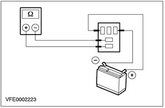
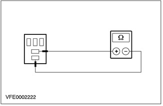
3. Check relay contact in switched position.
- Connect the positive pin of the power supply to pin 1.
- Connect the negative pin of the power supply to pin 2.
- Check the resistance between pin 3 and pin 5.
- Does the relay switch with a distinct sound and the resistance is less than 1 ohm?
- If so, the relay is good.
- If not, replace the relay.
Visitor comments