|
STATES |
DETAILS/RESULTS/ACTIONS |
|
AW1: IDENTIFY THE STATE IN WHICH THE FAULT IS APPEARING. |
|
|
1 Drive the ON position. |
|
|
2 Set the gearbox to "REVERSE". |
|
|
3 Check for non-working reversing light. |
|
|
• One reversing light not working? |
|
|
→ Yes |
|
|
Left reversing light not working: Go to AW2 |
|
|
Right reversing light not working: Go to AW4 |
|
|
→ No |
|
|
Both reversing lights not working, manual transmission: Go to AW6 |
|
|
Both reversing lights not working, automatic transmission: Go to AW11 |
|
|
AW2: CHECK THE POWER SUPPLY OF THE REAR LIGHT UNIT, LEFT SIDE |
|
|
1 Enter the OFF position. |
|
|
2 Disconnect the tail light unit, left side - C476. |
|
|
3 Drive the ON position. |
|
|
4 Set the gearbox to "REVERSE". |
|
|
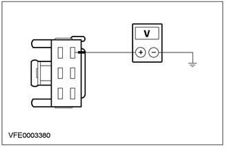
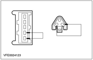
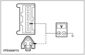
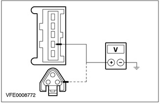
5 Measure the voltage between pin 4 C476 of the rear light unit, left side, circuit 15S-LG9A (green/black), from the wiring side and "weight". |
|
• Does the battery voltage register? |
|
|
→ Yes |
|
|
Go to AW3 |
|
|
→ No |
|
|
REPAIR open circuit 15S-LG9A (green/black) between connection S211 and rear light unit, left side, using the wiring diagrams. Check the correct operation of the system. |
|
|
AW3: CHECK CONNECTION WITH "MASS" TAIL LIGHT UNIT, LEFT |
|
|
1 Enter the OFF position. |
|

|
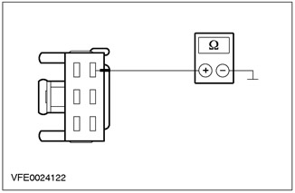
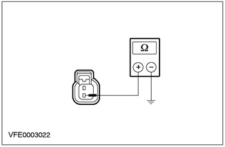
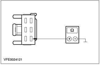
2 Measure the resistance between pin 6 C476 of the rear light unit, left side, circuit 31-LF23 (black), from the wiring side and "weight". |
|
• Is the resistance less than 2 ohms? |
|
|
→ Yes |
|
|
CHECK rear light unit, left side. If necessary, INSTALL the new element. Check the correct operation of the system. |
|
|
→ No |
|
|
REPAIR open circuit 31-LF23 (black) between rear light unit, left side, and "weight" G46 using the wiring diagrams. Check the correct operation of the system. |
|
|
AW4: CHECK THE POWER SUPPLY OF THE REAR LIGHT UNIT, RIGHT SIDE |
|
|
1 Enter the OFF position. |
|
|
2 Disconnect the Tail Light Unit, Right Side - C477. |
|
|
3 Drive the ON position. |
|
|
4 Set the gearbox to "REVERSE". |
|
|
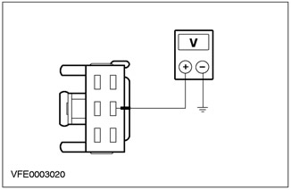
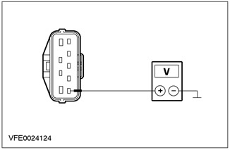
5 Measure the voltage between pin 5 C477 of the rear light unit, right side, circuit 15S-LG16 (green/orange), from the wiring side and "weight". |
|
• Does the battery voltage register? |
|
|
→ Yes |
|
|
Go to AW5 |
|
|
→ No |
|
|
REPAIR open circuit 15S-LG16 (green/orange) between connection S211 and rear light unit, right side, using the wiring diagrams. Check the correct operation of the system. |
|
|
AW5: CHECK CONNECTION WITH "MASS" TAIL LAMP UNIT, RIGHT SIDE |
|
|
1 Enter the OFF position. |
|
|
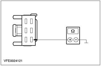
2 Measure the resistance between pin 4 C477 of the rear light unit, right side, of circuit 31-LF24 (black), from the wiring side and "weight". |
|
• Is the resistance less than 2 ohms? |
|
|
→ Yes |
|
|
CHECK rear light unit, right side. If necessary, INSTALL the new element. Check the correct operation of the system. |
|
|
→ No |
|
|
REPAIR open circuit 31-LF24 (black) between the rear light unit, right side and "weight" G47 (up to 01/2000) or G46 (from 01/2000), using electrical diagrams. Check the correct operation of the system. |
|
|
AW6: CHECK FUSE F53 |
|
|
1 Enter the OFF position. |
|
|
2 Disconnect F53 Fuse. |
|
|
3 CHECK FUSE F53 (10 A) |
|
|
• Is the fuse good? |
|
|
→ Yes |
|
|
Go to AW7 |
|
|
→ No |
|
|
Install new fuse F53 (10 A). If the fuse blows again, LOCATE and REPAIR the short circuit using the wiring diagrams. Check the correct operation of the system. |
|
|
AW7: CHECK POWER SUPPLY OF F53 FUSE |
|
|
1 Connect Fuse F53 (CJB). |
|
|
2 Drive the ON position. |
|
|
3 Measure voltage between fuse F53 (CJB) And "weight". |
|
|
• Does the battery voltage register? |
|
|
→ Yes |
|
|
Go to AW8 |
|
|
→ No |
|
|
RESTORE power to fuse F53 using the wiring diagrams. Check the correct operation of the system. |
|
|
AW8: CHECK PARK/NEUTRAL POSITION SWITCH |
|
|
1 Enter the OFF position. |
|
|
2 Disconnect Park/Neutral Position Switch - C862 (Endura-DI/MTX-manual transmission) /C864 (all others). |
|

|
3 Connect the connecting wire to connector C862 (Endura-DI/MTX-manual transmission) / C864 (all others), park/neutral position switch between pin 2, electrical circuit 15-LG28 (green/white), from the wiring side, and pin 1, electrical circuit 15S-LG3 (green/yellow), from the side of the electrical wiring. |
|
4 Drive the ON position. |
|
|
5 Check the reversing lights. |
|
|
• Are the reversing lights on? |
|
|
→ Yes |
|
|
Go to AW9 |
|
|
→ No |
|
|
CHECK the park/neutral position switch. If necessary, INSTALL the new element. Check the correct operation of the system. |
|
|
AW9: CHECK POWER SUPPLY TO PARK/NEUTRAL SWITCH |
|

|
1 Measure voltage between pin 2 C862 (Endura-DI/MTX-manual transmission) / C864 (all others) park/neutral position switch, circuit 15-LG28 (green/white), from the wiring side and "weight". |
|
• Does the battery voltage register? |
|
|
→ Yes |
|
|
Before 01/2000: REPAIR the open circuit (to her) between the park/neutral position switch and connection S211, using the wiring diagrams. Check the correct operation of the system. |
|
|
From 01/2000: Go to AW10 |
|
|
→ No |
|
|
RESTORE power to the park/neutral position switch using the wiring diagrams. Check the correct operation of the system. |
|
|
AW10: CHECK CONNECTION WITH "MASS" TAIL LIGHT UNIT, LEFT |
|
|
1 Disconnect the tail light assembly, left side - C476. |
|
|
2 Measure the resistance between pin 6 C476 of the rear light unit, left side, circuit 31-LF23 (black), from the wiring side and "weight". |
|
• Is the resistance less than 2 ohms? |
|
|
→ Yes |
|
|
REPAIR open circuit (to her) between the park/neutral position switch and connection S211, using the wiring diagrams. Check the correct operation of the system. |
|
|
→ No |
|
|
REPAIR open circuit 31-LF23 (black) between connection S184 and "weight" G46 using the wiring diagrams. Check the correct operation of the system. |
|
|
AW11: CHECK FUSE F39 |
|
|
1 Enter the OFF position. |
|
|
2 CHECK Fuse F39 (CJB). |
|
|
3 CHECK FUSE F39 (10 A) |
|
|
• Is the fuse good? |
|
|
→ Yes |
|
|
Go to AW12 |
|
|
→ No |
|
|
Install new fuse F39 (10 A). If the fuse blows again, LOCATE and REPAIR the short circuit using the wiring diagrams. Check the correct operation of the system. |
|
|
AW12: CHECK TRANSMISSION RANGE SENSOR POWER SUPPLY |
|
|
1 Connect Fuse F39 (CJB). |
|
|
2 Disconnect the Transmission Range Sensor - C438. |
|
|
3 Drive the ON position. |
|

|
4 Measure the voltage between C438 pin 1 of the transmission range sensor circuit 15-TA18 (green/orange), from the wiring side and "weight". |
|
• Does the battery voltage register? |
|
|
→ Yes |
|
|
Go to AW13 |
|
|
→ No |
|
|
RESTORE power to the transmission range sensor using the wiring diagrams. Check the correct operation of the system. |
|
|
AW13: CHECK TRANSMISSION RANGE SENSOR |
|
|
1 Enter the OFF position. |
|
|
2 Disconnect the Transmission Range Sensor - C438. |
|

|
3 Connect the jumper wire to connector C438 of the transmission range sensor between pin 1, circuit 15-TA18 (green/orange), from the wiring side, and pin 4, electrical circuit 15S-TA38 (green/blue), from the side of the electrical wiring. |
|
4 Drive the ON position. |
|
|
5 Check the reversing lights. |
|
|
• Are the reversing lights on? |
|
|
→ Yes |
|
|
CHECK transmission range sensor. If necessary, INSTALL the new element. Check the correct operation of the system. |
|
|
→ No |
|
|
Go to AW14 |
|
|
AW14: CHECK POWER SUPPLY OF F39 FUSE |
|
|
1 Enter the OFF position. |
|

|
2 Connect the jumper wire to connector C438 of the transmission range sensor, between pin 1, circuit 15-TA18 (green/orange), from the wiring side, and pin 4, electrical circuit 15S-TA38 (green/blue), from the side of the electrical wiring. |
|
3 Drive the ON position. |
|
|
4 Measure the voltage between fuse F39 and "weight". |
|
|
• Does the battery voltage register? |
|
|
→ Yes |
|
|
Before 01/2000: REPAIR the open circuit (to her) between fuse F39 and connection S211 using the wiring diagrams. Check the correct operation of the system. |
|
|
From 01/2000: Go to AW15 |
|
|
→ No |
|
|
RESTORE power to fuse F39 using the wiring diagrams. Check the correct operation of the system. If necessary, INSTALL a new CJB. |
|
|
AW15: CHECK CONNECTION WITH "MASS" TAIL LIGHT UNIT, LEFT |
|
|
1 Enter the OFF position. |
|
|
2 Disconnect the tail light unit, left side - C476. |
|

|
3 Measure the resistance between pin 6 C476 of the rear light unit, left side, circuit 31-LF23 (black), from the wiring side and "weight". |
|
• Is the resistance less than 2 ohms? |
|
|
→ Yes |
|
|
REPAIR open circuit (to her) between fuse F39 and connection S211 using the wiring diagrams. Check the correct operation of the system. If necessary, INSTALL a new CJB. |
|
|
→ No |
|
|
REPAIR open circuit 31-LF23 (black) between connection S184 and "weight" G46 using the wiring diagrams. Check the correct operation of the system. |
|
PINPOINT TEST AX: REVERSE LAMP DOES NOT WORK, 3/5-DOOR MODELS ONLY
|
STATES |
DETAILS/RESULTS/ACTIONS |
|
AX1: DEFINE VEHICLE TRANSMISSION TYPE |
|
|
1 Determine the type of vehicle gearbox. |
|
|
• Is the vehicle equipped with a manual transmission? |
|
|
→ Yes |
|
|
Go to AX2 |
|
|
→ No |
|
|
Go to AX7 |
|
|
AX2: CHECK F53 FUSE |
|
|
1 Enter the OFF position. |
|
|
2 Disconnect Fuse F53 (CJB). |
|
|
3 CHECK FUSE F53 (10 A) |
|
|
• Is the fuse good? |
|
|
→ Yes |
|
|
Go to AX3 |
|
|
→ No |
|
|
Install new fuse F53 (10 A). If the fuse blows again, LOCATE and REPAIR the short circuit using the wiring diagrams. Check the correct operation of the system. |
|
|
AX3: CHECK POWER SUPPLY OF F53 FUSE |
|
|
1 Connect F53 CJB Fuse. |
|
|
2 Drive the ON position. |
|
|
3 Measure voltage between fuse F53 (CJB) And "weight". |
|
|
• Does the battery voltage register? |
|
|
→ Yes |
|
|
Go to AX4 |
|
|
→ No |
|
|
RESTORE power to fuse F53 using the wiring diagrams. Check the correct operation of the system. |
|
|
AX4: CHECK PARK/NEUTRAL POSITION SWITCH |
|
|
1 Enter the OFF position. |
|
|
2 Disconnect Park/Neutral Position Switch - C862 (Endura-DI/MTX-manual transmission) /C864 (all others). |
|
|
3 Connect the connecting wire to connector C862 (Endura-DI/MTX-manual transmission) / C864 (all others) park/neutral position switch, between pin 2, circuit 15-LG28 (green/white), side wiring and pin 1, electrical circuit 15S-LG3 (green/yellow), from the side of the electrical wiring. |
|
4 Drive the ON position. |
|
|
5 Check the reverse light. |
|
|
• Is the reversing light on? |
|
|
→ Yes |
|
|
Go to AX5 |
|
|
→ No |
|
|
CHECK the park/neutral position switch. If necessary, INSTALL the new element. Check the correct operation of the system. |
|
|
AX5: CHECK POWER SUPPLY TO PARK/NEUTRAL SWITCH |
|
|
1 Measure voltage between pin 2 C862 (Endura-DI/MTX-manual transmission) / C864 (all others) park/neutral position switch, circuit 15-LG28 (green/white), from the wiring side and "weight". |
|
• Does the battery voltage register? |
|
|
→ Yes |
|
|
Go to AX6 |
|
|
→ No |
|
|
RESTORE power to the park/neutral position switch using the wiring diagrams. Check the correct operation of the system. |
|
|
AX6: CHECK REVERSE LIGHT GROUND |
|
|
1 Enter the OFF position. |
|
|
2 Disconnect Reversing light - C430 (up to 09/1999) / C429 (from 09/1999). |
|
|
3 Measure the resistance between the reversing light: - LHD: Right side, pin 2 C430 (up to 09/1999) / C429 (from 09/1999), electrical circuit 31-LG16 (black), from the wiring side and "weight". - RHD: Left side, pin 2 C430 (up to 09/1999) / C429 (from 09/1999), electrical circuit 31-LG9 (black), from the wiring side and "weight". |
|
• Is the resistance less than 2 ohms? |
|
|
→ Yes |
|
|
REPAIR open circuit (to her) between the park/neutral position switch and the reversing lamp, using the wiring diagrams. Check the correct operation of the system. |
|
|
→ No |
|
|
REPAIR open circuit (to her) between the reversing lamp and "weight" G46 using the wiring diagrams. Check the correct operation of the system. |
|
|
AX7: CHECK FUSE F39 |
|
|
1 Enter the OFF position. |
|
|
2 CHECK Fuse F39 (CJB). |
|
|
3 CHECK FUSE F39 (10 A) |
|
|
• Is the fuse good? |
|
|
→ Yes |
|
|
Go to AX8 |
|
|
→ No |
|
|
Install new fuse F39 (10 A). If the fuse blows again, LOCATE and REPAIR the short circuit using the wiring diagrams. Check the correct operation of the system. |
|
|
AX8: CHECK TRANSMISSION RANGE SENSOR POWER SUPPLY |
|
|
1 Connect Fuse F39 (CJB). |
|
|
2 Disconnect the Transmission Range Sensor - C438. |
|
|
3 Drive the ON position. |
|
|
4 Measure the voltage between C438 pin 1 of the transmission range sensor circuit 15-TA18 (green/orange), from the wiring side and "weight". |
|
• Does the battery voltage register? |
|
|
→ Yes |
|
|
Go to AX9 |
|
|
→ No |
|
|
RESTORE power to the transmission range sensor using the wiring diagrams. Check the correct operation of the system. |
|
|
AX9: CHECK TRANSMISSION RANGE SENSOR |
|
|
1 Enter the OFF position. |
|

|
2 Connect the jumper wire to connector C438 of the transmission range sensor between pin 1, circuit 15-TA18 (green/orange), from the wiring side, and pin 4, electrical circuit 15S-TA38 (green/blue), from the side of the electrical wiring. |
|
3 Drive the ON position. |
|
|
4 Check the reversing light. |
|
|
• Is the reversing light on? |
|
|
→ Yes |
|
|
CHECK transmission range sensor. If necessary, INSTALL the new element. Check the correct operation of the system. |
|
|
→ No |
|
|
Go to AX10 |
|
|
AX10: CHECK POWER SUPPLY OF F39 FUSE |
|
|
1 Enter the OFF position. |
|

|
2 Connect the jumper wire to connector C438 of the transmission range sensor, between pin 1, circuit 15-TA18 (green/orange), from the wiring side, and pin 4, electrical circuit 15S-TA38 (green/blue), from the side of the electrical wiring. |
|
3 Drive the ON position. |
|
|
4 Measure the voltage between fuse F39 and "weight". |
|
|
• Does the battery voltage register? |
|
|
→ Yes |
|
|
Go to AX11 |
|
|
→ No |
|
|
RESTORE power to fuse F39 using the wiring diagrams. Check the correct operation of the system. If necessary, INSTALL a new CJB. |
|
|
AX11: CHECK REVERSE LAMP GROUND |
|
|
1 Enter the OFF position. |
|
|
2 Disconnect Reversing light - C430 (up to 09/1999) / C429 (from 09/1999). |
|

|
3 Measure the resistance between the reversing light: - LHD: Right side, pin 2 C430 (up to 09/1999) / C429 (from 09/1999), electrical circuit 31-LG16 (black), from the wiring side, and "weight". - RHD: Left side, pin 2 C430 (up to 09/1999) / C429 (from 09/1999), electrical circuit 31-LG9 (black), from the wiring side, and "weight". |
|
• Is the resistance less than 2 ohms? |
|
|
→ Yes |
|
|
REPAIR open circuit (to her) between the park/neutral position switch and the reversing lamp, using the wiring diagrams. Check the correct operation of the system. |
|
|
→ No |
|
|
REPAIR open circuit (to her) between the reversing lamp and "weight" G46 using the wiring diagrams. Check the correct operation of the system. |
|
PINPOINT TEST AY: REVERSE LAMP DOES NOT WORK, MODELS ONLY "UNIVERSAL"
|
STATES |
DETAILS/RESULTS/ACTIONS |
|
AY1: IDENTIFY VEHICLE TRANSMISSION TYPE |
|
|
1 Determine the type of vehicle gearbox. |
|
|
• Is the vehicle equipped with a manual transmission? |
|
|
→ Yes |
|
|
Go to AY2 |
|
|
→ No |
|
|
Go to AY7 |
|
|
AY2: CHECK F53 FUSE |
|
|
1 Enter the OFF position. |
|
|
2 Disconnect Fuse F53 (CJB). |
|
|
3 CHECK FUSE F53 (10 A) |
|
|
• Is the fuse good? |
|
|
→ Yes |
|
|
Go to AY3 |
|
|
→ No |
|
|
Install new fuse F53 (10 A). If the fuse blows again, LOCATE and REPAIR the short circuit using the wiring diagrams. Check the correct operation of the system. |
|
|
AY3: CHECK POWER SUPPLY OF F53 FUSE |
|
|
1 Connect F53 CJB Fuse. |
|
|
2 Drive the ON position. |
|
|
3 Measure voltage between fuse F53 (CJB) And "weight". |
|
|
• Does the battery voltage register? |
|
|
→ Yes |
|
|
Go to AY4 |
|
|
→ No |
|
|
RESTORE power to fuse F53 using the wiring diagrams. Check the correct operation of the system. |
|
|
AY4: CHECK PARK/NEUTRAL POSITION SWITCH |
|
|
1 Enter the OFF position. |
|
|
2 Disconnect Park/Neutral Position Switch - C862 (Endura-DI/MTX-manual transmission) /C864 (all others). |
|

|
3 Connect the connecting wire to connector C862 (Endura-DI/MTX-manual transmission) /C864 (all others) park/neutral position switch between pin 2, circuit 15-LG28 (green/white), from the wiring side, and pin 1, electrical circuit 15S-LG3 (green/yellow), from the side of the electrical wiring. |
|
4 Drive the ON position. |
|
|
5 Check the reverse light. |
|
|
• Is the reversing light on? |
|
|
→ Yes |
|
|
Go to AY5 |
|
|
→ No |
|
|
CHECK the park/neutral position switch. If necessary, INSTALL the new element. Check the correct operation of the system. |
|
|
AY5: CHECK POWER SUPPLY TO PARK/NEUTRAL SWITCH |
|
|
1 Measure voltage between pin 2 C862 (Endura-DI/MTX-manual transmission) /C864 (all others) park/neutral position switch, circuit 15-LG28 (green/white), from the wiring side and "weight". |
|
• Does the battery voltage register? |
|
|
→ Yes |
|
|
Go to AY6 |
|
|
→ No |
|
|
RESTORE power to the park/neutral position switch using the wiring diagrams. Check the correct operation of the system. |
|
|
AY6: CHECK REVERSE LIGHT GROUND |
|
|
1 Enter the OFF position. |
|
|
2 Disconnect Rear light unit - C474 (LHD) / C475 (RHD). |
|
|
3 Measure the resistance between the reversing light: - LHD: Right side, pin 6 C475, circuit 31-LF24A (black), from the wiring side and "weight". - RHD: Left side, pin 6 C474, electrical circuit 31-LF23A (black), from the wiring side and "weight". |
|
• Is the resistance less than 2 ohms? |
|
|
→ Yes |
|
|
REPAIR open circuit (to her) between the park/neutral position switch and the reversing lamp, using the wiring diagrams. Check the correct operation of the system. |
|
|
→ No |
|
|
REPAIR open circuit (to her) between the reversing lamp and "weight" G47 (LHD, up to 01/2000) / G46 (all others), using electrical diagrams. Check the correct operation of the system. |
|
|
AY7: CHECK F39 FUSE |
|
|
1 Enter the OFF position. |
|
|
2 CHECK Fuse F39 (CJB). |
|
|
3 CHECK FUSE F39 (10 A) |
|
|
• Is the fuse good? |
|
|
→ Yes |
|
|
Go to AY8 |
|
|
→ No |
|
|
Install new fuse F39 (10 A). If the fuse blows again, LOCATE and REPAIR the short circuit using the wiring diagrams. Check the correct operation of the system. |
|
|
AY8: CHECK TRANSMISSION RANGE SENSOR POWER SUPPLY |
|
|
1 Connect Fuse F39 (CJB). |
|
|
2 Disconnect the Transmission Range Sensor - C438. |
|
|
3 Drive the ON position. |
|

|
4 Measure the voltage between C438 pin 1 of the transmission range sensor circuit 15-TA18 (green/orange), from the wiring side and "weight". |
|
• Does the battery voltage register? |
|
|
→ Yes |
|
|
Go to AY9 |
|
|
→ No |
|
|
RESTORE power to the transmission range sensor using the wiring diagrams. Check the correct operation of the system. |
|
|
AY9: CHECK TRANSMISSION RANGE SENSOR |
|
|
1 Enter the OFF position. |
|
|
2 Connect the jumper wire to connector C438 of the transmission range sensor between pin 1, circuit 15-TA18 (green/orange), from the wiring side, and pin 4, electrical circuit 15S-TA38 (green/blue), from the side of the electrical wiring. |
|
3 Drive the ON position. |
|
|
4 Check the reversing light. |
|
|
• Is the reversing light on? |
|
|
→ Yes |
|
|
CHECK transmission range sensor. If necessary, INSTALL the new element. Check the correct operation of the system. |
|
|
→ No |
|
|
Go to AY10 |
|
|
AY10: CHECK POWER SUPPLY OF F39 FUSE |
|
|
1 Enter the OFF position. |
|

|
2 Connect the jumper wire to connector C438 of the transmission range sensor between pin 1, circuit 15-TA18 (green/orange), from the wiring side, and pin 4, electrical circuit 15S-TA38 (green/blue), from the side of the electrical wiring. |
|
3 Measure the voltage between fuse F39 and "weight". |
|
|
4 Drive the ON position. |
|
|
• Does the battery voltage register? |
|
|
→ Yes |
|
|
Go to AY11 |
|
|
→ No |
|
|
RESTORE power to fuse F39 using the wiring diagrams. Check the correct operation of the system. If necessary, INSTALL a new CJB. |
|
|
AY11: CHECK REVERSE LAMP GROUND |
|
|
1 Enter the OFF position. |
|
|
2 Disconnect Rear light unit - C474 (LHD) / C475 (RHD). |
|

|
3 Measure the resistance between the reversing light: - LHD: Right side, pin 6 C475, circuit 31-LF24A (black), from the wiring side and "weight". - RHD: Left side, pin 6 C474, electrical circuit 31-LF23A (black), from the wiring side and "weight". |
|
• Is the resistance less than 2 ohms? |
|
|
→ Yes |
|
|
REPAIR open circuit (to her) between the park/neutral position switch and the tail light unit using the wiring diagrams. Check the correct operation of the system. |
|
|
→ No |
|
|
REPAIR open circuit (to her) between the reversing lamp and "weight" G47 (LHD, up to 01/2000) / G46 (all others), using electrical diagrams. Check the correct operation of the system. |
|
PINPOINT TEST AZ: LANTERN (AND) REVERSE LIGHT ON CONSTANTLY
|
STATES |
DETAILS/RESULTS/ACTIONS |
|
AZ1: IDENTIFY YOUR VEHICLE GEARBOX |
|
|
1 Determine the type of vehicle gearbox. |
|
|
• Does the car come with an automatic transmission? |
|
|
→ Yes |
|
|
Go to AZ2 |
|
|
→ No |
|
|
Go to AZ6 |
|
|
AZ2: DETERMINE SHORT TO POWER SUPPLY |
|
|
1 Enter the OFF position. |
|
|
2 Disconnect Fuse F39 (CJB). |
|
|
3 Drive the ON position. |
|
|
4 Check the lantern (And) reverse. |
|
|
• Flashlight (And) reverse lights on? |
|
|
→ Yes |
|
|
Japan only: Go to AZ3 |
|
|
All others: REPAIR short to circuit power source (to her), connected to fuse F39 using the wiring diagrams. CHECK the system is working properly. |
|
|
→ No |
|
|
Go to AZ4 |
|
|
AZ3: CHECK CENTRAL TIMER MODULE FOR SHORT TO POWER SUPPLY |
|
|
1 Enter the OFF position. |
|
|
2 Disconnect the Central Timer Module (CTM) - C1000. |
|
|
3 Drive the ON position. |
|
|
4 Check the lantern (And) reverse. |
|
|
• Flashlight (And) reverse lights on? |
|
|
→ Yes |
|
|
REPAIR short to circuit power supply (to her), connected to connection S13 using the wiring diagrams. CHECK the system is working properly. |
|
|
→ No |
|
|
Check the CTM module. If necessary, INSTALL the new element. CHECK the system is working properly. |
|
|
AZ4: CHECK TRANSMISSION RANGE SENSOR FUNCTIONS CORRECTLY |
|
|
1 Enter the OFF position. |
|
|
2 Connect Fuse F39 (CJB). |
|
|
3 Disconnect the Transmission Range Sensor - C438. |
|
|
4 Drive the ON position. |
|
|
5 Check the lantern (And) reverse. |
|
|
• Flashlight (And) reverse lights on? |
|
|
→ Yes |
|
|
Go to AZ5 |
|
|
→ No |
|
|
CHECK transmission range sensor. If necessary, INSTALL the new element. CHECK the system is working properly. |
|
|
AZ5: CHECK POWERTRAIN CONTROL MODULE FOR CORRECT OPERATION (PCM) |
|
|
1 Enter the OFF position. |
|
|
2 Disconnect PCM - C415. |
|
|
3 Drive the ON position. |
|
|
4 Check the lantern (And) reverse. |
|
|
• Flashlight (And) reverse lights on? |
|
|
→ Yes |
|
|
REPAIR short to circuit power supply (to her), connected to the S75 connection using the wiring diagrams. CHECK the system is working properly. |
|
|
→ No |
|
|
CHECK PCM. If necessary, INSTALL the new element. CHECK the system is working properly. |
|
|
AZ6: CHECK PARK/NEUTRAL POSITION SWITCH |
|
|
1 Enter the OFF position. |
|
|
2 Disconnect Park/Neutral Position Switch - C862 (Endura-DI/MTX-manual transmission) /C864 (all others). |
|
|
3 Drive the ON position. |
|
|
4 Check the lantern (And) reverse. |
|
|
• Flashlight (And) reverse lights on? |
|
|
→ Yes |
|
|
Japan only: Go to AZ7 |
|
|
All others: REPAIR short to circuit power source (to her), connected to the park/neutral position switch using the wiring diagrams. CHECK the system is working properly. |
|
|
→ No |
|
|
CHECK the park/neutral position switch. If necessary, INSTALL the new element. CHECK the system is working properly. |
|
|
AZ7: CHECK THE CENTRAL TIMER MODULE IS CORRECTLY OPERATING |
|
|
1 Enter the OFF position. |
|
|
2 Disconnect the Central Timer Module (CTM) - C1000. |
|
|
3 Drive the ON position. |
|
|
4 Check the lantern (And) reverse. |
|
|
• Flashlight (And) reverse lights on? |
|
|
→ Yes |
|
|
REPAIR short to circuit power supply (to her), connected to connection S13 using the wiring diagrams. CHECK the system is working properly. If necessary, INSTALL a new CJB. |
|
|
→ No |
|
|
CHECK CTM. If necessary, INSTALL the new element. CHECK the system is working properly. |
|
Visitor comments