Crank mechanism
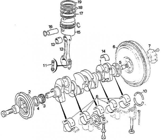
1 - crankshaft, 2 - pulley, 3 - sprocket, 4 - sealing ring, 5 - centering sleeve of the primary shaft of the gearbox, 6 - flywheel, 7 - washer for fixing the flywheel mounting bolts, 8 - main bearing shells, 9 - crankshaft thrust half rings, 10 - rear main bearing seals, 11 - connecting rod bolt, 12 - connecting rod, 13 - connecting rod head bushing, 14 - connecting rod bearing shell, 15 - piston, 16 - piston pin, 17 - oil scraper ring, 18 - lower sealing ring, 19 - upper sealing ring (compression)
1. Check the condition of the connecting rod.
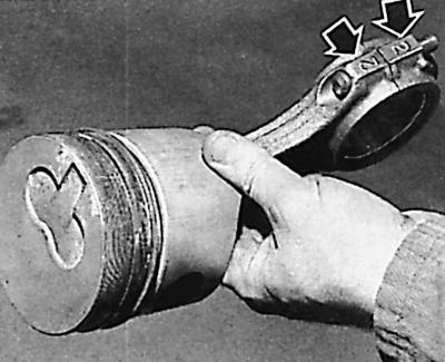
2. Observe the correct installation - the recesses on the bottom of the piston must be directed in the same direction as the markings on the connecting rod and its cover (arrows).
3. Lubricate the piston pin with a thin layer of engine oil and install it in the connecting rod head bushing.
4. Carefully install the spring retaining rings into the piston grooves to secure the pin in the piston.
5. Using a special device, install the rings on the pistons with the side marked "Top" facing the bottom. The rings are supplied ready for installation. The rings should move freely in the piston grooves, but without a noticeable gap.
6. Place the rings in the piston grooves so that the locks (cuts) of the sealing rings are offset relative to each other on opposite sides at an angle of 120° relative to the cut of the oil scraper ring.
Selection of pistons by cylinder diameter
Cylinder Block Assembly
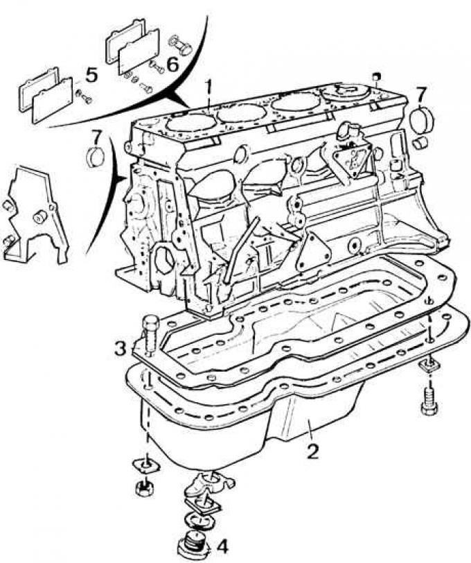
1 – cylinder block, 2 – oil pan, 3 – oil pan mounting bolt, 4 – oil drain plug, 5 – cylinder block access hole covers, 6 – bolt, 7 – access hole plug
Designations of cylinders on the engine cylinder block and pistons on their bottom
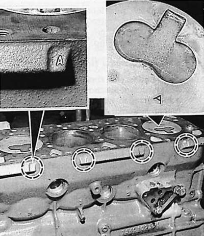
1. The diameters of the pistons and cylinders are divided into groups, which are designated by letters stamped on the engine cylinder block and the piston crown.
2. The cylinder and the piston interacting with it must belong to the same selection group (see Fig. Designations of cylinders on the engine cylinder block and pistons on their bottom).
Attention! New engine cylinder blocks have cylinders with diameters of groups "A" and "B" only.
3. Lubricate the piston surfaces and inner surfaces of the cylinders with oil.
4. Using a ring compressor, insert the piston-connecting rod assemblies into the corresponding cylinders.
Caution! The recess at the bottom of the piston must be directed towards the fuel pump.
5. Press the pistons deep into the cylinders.
6. Install the connecting rod bearings and connecting rod caps (observing the designations - see Fig. Designation of the relative positions of the piston, connecting rod and its cap), tighten the nuts of the connecting rod cap bolts to a torque of 60 Nm.
7. Measure the moment of resistance when rotating the crankshaft using a torque wrench.
8. Lubricate the tappets with oil and insert them in accordance with the markings and into the guides of the engine cylinder block.
9. Install the camshaft and intermediate plate into the cylinder block together with a new gasket.
10. Install the timing drive (see subsection 4.2.11.3.3) and the timing chain cover together with a new gasket.
11. Lubricate the timing chain housing bolts with Frenetanch sealing paste and tighten them to a torque of 10 Nm.
12. Attach the oil pump to the cylinder block so that the conical hole in the pump body is located opposite the threaded hole.
13. Tighten the oil pump mounting bolt (with a conical end) to a torque of 22.5 Nm.
14. Install the copper washer and tighten the plugged hole nut to 30 Nm.
15. Install the original adjusting washer and carefully tighten the threaded plug.
16. Install the oil pan. Tighten the drain plug with a new gasket to 3 Nm.
For details, please visit the website [FORDBOOK.ru]