Withdrawal
Mark the position of the front wheel on the hub with paint. Thanks to this, the balanced wheel can be installed again in its original position. When loosening the wheel nuts, the car must stand on the site. Raise the front of the car on jack stands and remove the front wheel.
Suspend the brake caliper on a wire to the wheel arch trim so that the brake hose is not twisted or stretched. Do not disconnect the brake hose, otherwise it will be necessary to remove air from the brake system after installation.
Remove the ABS sensor mounting bolt and remove the sensor from the swivel bearing.
Remove brake disc see p. 116.
Press the tie rod end out of the swivel bearing, see p. 105.
Caution: Wrap a cloth around the tie rod end after removing it from the swivel bearing to protect it from damage.
Models up to 8/94: Remove the control arm ball joint from the pivot point by removing the locking cotter pin and loosening the castle nut. Press the control arm ball joint out of the swivel bearing using a ball joint extractor, eg HAZET 779, and unscrew the slotted nut.
Models from 9/94: Unscrew the nut -arrow- of the retaining bolt for the ball joint.
Pull the transverse link downwards out of the swivel bearing.
Attention: Make sure that the rubber seal of the ball joint is not damaged. Wrap the ball joint with a rag.
Unscrew the locking bolt for the suspension strut from the swivel bearing.
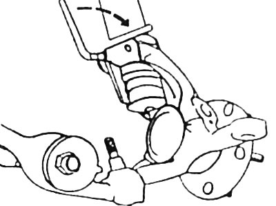
Open the swivel bearing using FORD 13-006 tool. To do this, insert the spreader lever into the slot of the swivel bearing and turn it by 90°. A suitable chisel or pry bar can also be used for this operation. In any case, care must be taken not to damage any parts.
Remove the swivel support from the spring strut downwards.
Installation
Slide the swivel mount onto the suspension strut. Turn the lever of the FORD special tool 90°back and remove the tool.
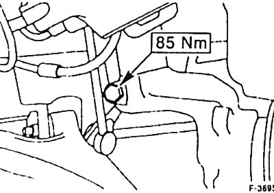
Insert a new self-locking locking bolt for the suspension strut into the pivot mount. Tighten the locking bolt to 85 Nm.
Models up to 8/94: Insert the ball joint pin of the control arm into the pivot bearing. Screw on castle nut, tighten to 85 Nm and secure with a new cotter pin. If the cotter pin does not fit into the hole, do not loosen the castle nut, but tighten it further so that the cotter pin goes into the hole.
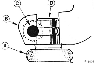
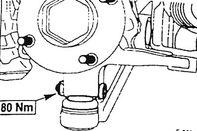
Models since 9/94; Press ball joint of transverse link from below into swivel bearing -B- as far as it will go. Insert the bolt -C- from the front, it must pass through the groove on the pin -D- of the control arm ball joint.
Attention: The head of the bolt must be facing the direction of the vehicle. Tighten the new self-locking bolt nut to 80 Nm, A - dust seal.
Install brake disc, see p. 116.
Insert the ABS sensor into the swivel bearing and tighten the mounting bolt.
Attention: before installing the sensor, check for damage and, if necessary, replace its sealing ring.
Install the brake caliper see p. 115.
If the brake hose has come loose, bleed the air from the brake system, see p. 117.
Insert the tie rod end into the pivot arm. Screw on castle nut, tighten to 30 Nm and secure with a new cotter pin. If the cotter pin does not fit into the hole, do not loosen the slotted nut, but tighten it further so that the cotter pin goes into the hole.
Check the mobility of the brake hose and ABS sensor wire. To do this, ask an assistant to turn the front wheels all the way to the right and left.
Attach the front wheel so that the marks made before removal coincide. Screw on wheel nuts. Lower the vehicle and tighten the wheel nuts crosswise to 100 Nm.
Visitor comments