Contents: Removal ↳ Installation ↳
Removal
Place the car over an inspection pit or on an overpass.
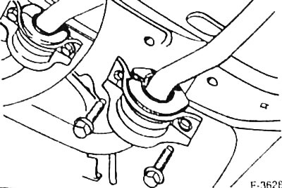
Unscrew the 4 bolts securing the stabilizer clamps and remove the clamps.
Attention: When removing the clamps, the car must stand on its wheels and not be supported by a garage jack.
Place the front of the car on jack stands.
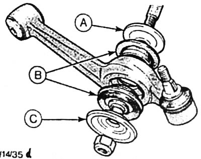
Unscrew the stabilizer mounting nut at the transverse arm. Remove the front disc washer "C". B - rubber bushings; A - rear disc washer.
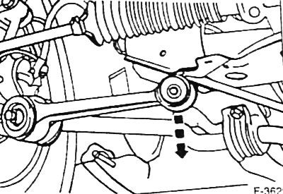
On one side of the car, unscrew the nut securing the inner support pin of the transverse arm and pull out the pin. Remove the lining washer.
Remove the wishbone from the engine support beam.
Remove the stabilizer from the rubber bushing of the released transverse arm.
Remove the stabilizer from the rubber bushing of the fixed transverse arm.
Remove the rubber support bushings from the stabilizer.
Note: The rubber bearing bushings have a welded metal bushing. Therefore, the bearing bushings should only be opened enough to be removed.
Installation
Note: The rubber support bushings have a welded metal bushing. The support bushings must not open during installation. To facilitate installation of the support bushings, lubricate the stabilizer with glycerin.
Place the support bushings on the stabilizer so that the slot in the mounting position faces the direction of vehicle movement, i.e. forward.
Insert the stabilizer into the rubber bushings of the transverse levers. Put the front, deeply concave black disc washers and front plastic caps on the ends of the stabilizer.
Screw new mounting nuts onto the ends of the stabilizer without tightening.
Insert the stunned transverse lever into the engine support beam, insert the support pin with the lining washer and tighten the fastening nut by hand.
Note: To install the wishbone support pin, have an assistant press inward on the outer edges of the wheel.
Lower the car.
Attach the stabilizer mounting clamps and tighten the bolts evenly to a torque of 90 Nm.
Caution: Make sure that the rubber support bushings are seated correctly and are not twisted.
Tighten the nut securing the support pin of the transverse arm to a torque of 30 Nm. Then, using a locked torque wrench, without interrupting the tightening, tighten the nuts by another 90° (1/4 turn).
Tighten the stabilizer mounting nuts to a torque of 110 Nm.