Note: There are design differences between vehicles before and after January 1999: the stabilizer links can be replaced separately. The nuts are tightened to 50 Nm.
- on all models of cars, the steering knuckle shaft is disconnected from the steering shaft friction clutch, to do this, unscrew the bolts and push the pressure plate to the side;
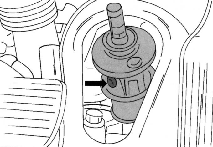
Fig. 200. Connection of the steering knuckle shaft to the friction clutch (all models)
- on vehicles manufactured before January 1999, remove the steering column trim from the base of the monocoque body, being careful not to damage it (it is secured with clamps to the rear and upper side), then grab the gasket from below and pull it upwards, on the shaft, disconnect the connection with the coupling in the place shown in Fig. 200;
- on vehicles manufactured since January 1999, unscrew only the connection with the friction clutch;
- loosen the wheel bolts, jack up the car and remove the front wheels;
- remove the engine splash guard and radiator trim from the rear side;
- disconnect the shock absorber struts from the subframe;
- Disconnect the anti-rotation stops;
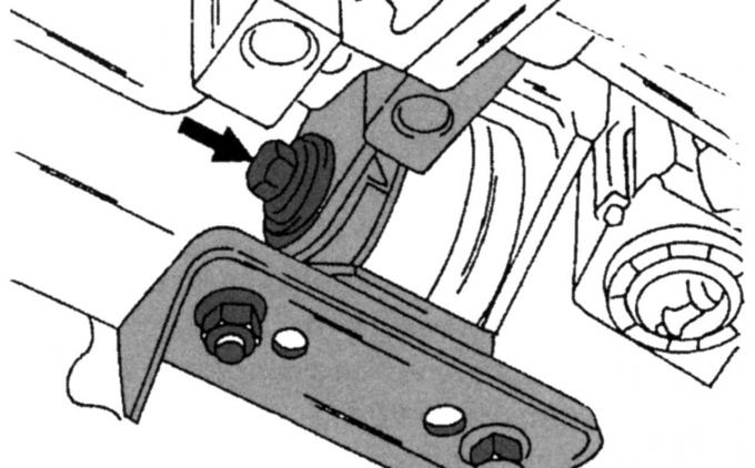
Fig. 170. Location of the front stop mounting screw
- on all gearboxes, unscrew the bolts shown in Fig. 170 and remove the front bearing;
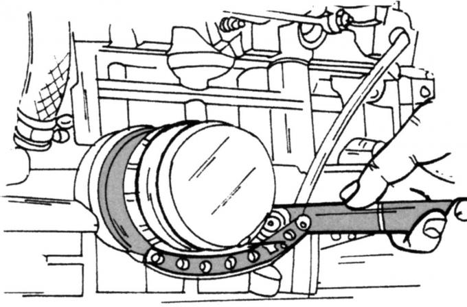
Fig. 117. Removing the oil filter
- on vehicles with a manual transmission, remove the bolt shown in Fig. 117 in the rear bearing nut
- disconnect the anti-roll bar connecting rod from the rear side;
- remove the safety plate in the rear area of the drive belt (one bolt on the left and right);
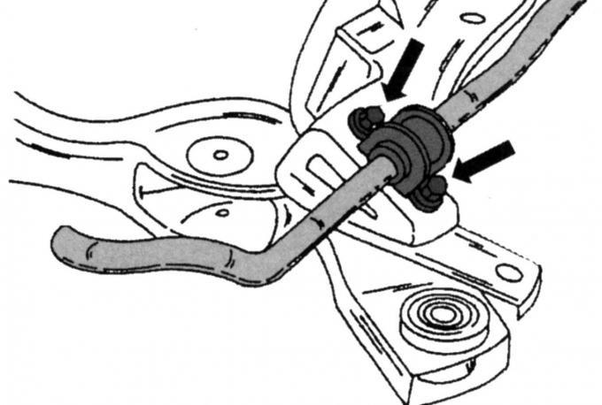
Fig. 201. Fastening the anti-roll bar to the subframe
- disconnect the subframe and lower it as described in Section 12.4 to gain access to the stabilizer bearing mount shown in Fig. 201;
- unscrew both bolts, remove the mounting clamp and take out the stabilizer (the rod must be disconnected on both sides).
Replacing the rubber bushings of both mounting clamps is not particularly difficult.
Installation is carried out in reverse order, taking into account the following:
Note: Observe the specified tightening torque values.
- tighten the stabilizer mounting clamp bolts to a torque of 25 Nm;
- install the subframe as described earlier and tighten the bolts to 130 Nm;
- tighten the stabilizer connecting rod to a torque of 50 Nm;
- tighten the bolt shown in Fig. 170 (manual gearbox) to a torque of 120 Nm;
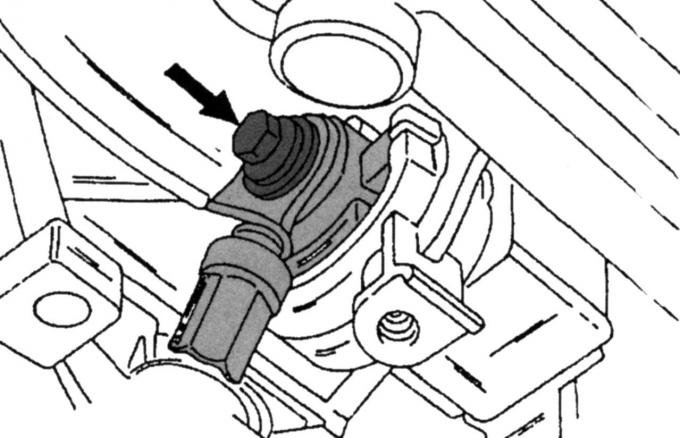
Fig. 171. Location of the rear stop mounting screw
- tighten the bolt shown in Fig. 171 (automatic transmission) to a torque of 120 Nm;
- tighten the friction clutch bolts to 19 Nm;
- reconnect the steering knuckle shaft to the steering shaft friction clutch;
- install the pressure plate in the correct position and tighten the bolts to a torque of 25 Nm.