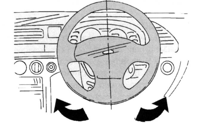
Fig. 205. Setting the steering wheel to a position corresponding to the straight-line movement of the vehicle
Check the wheel alignment as follows (first make sure that the steering wheel is set to the position corresponding to the straight-ahead movement of the vehicle (Fig. 205), this position is locked by the steering wheel shaft lock):
- apply the toe-in measurement template to the front side of the wheel rims at the height of the wheel hub;
- set the template to zero and mark with chalk on the wheel rims the locations of the two measuring pins;
- move the car forward by half a turn of the front wheels and place the template pins on the rear side of the wheel rims at the places marked with chalk, while moving the pins accordingly or spreading them apart and pressing them with the installation bolt;
- read the instrument reading.
When adjusting the toe-in, proceed as follows:
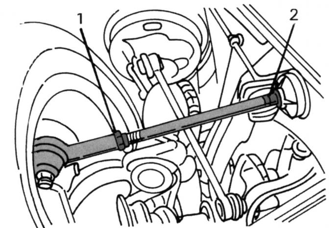
Fig. 206. Wheel alignment adjustment
- loosen the fastening clamps 2 (Fig. 206) of the steering gear cuffs at the inner ends of the transverse steering rod and the locknuts 1 of the transverse steering rod at the outer ends (left arrow), perform the work on the right and left;
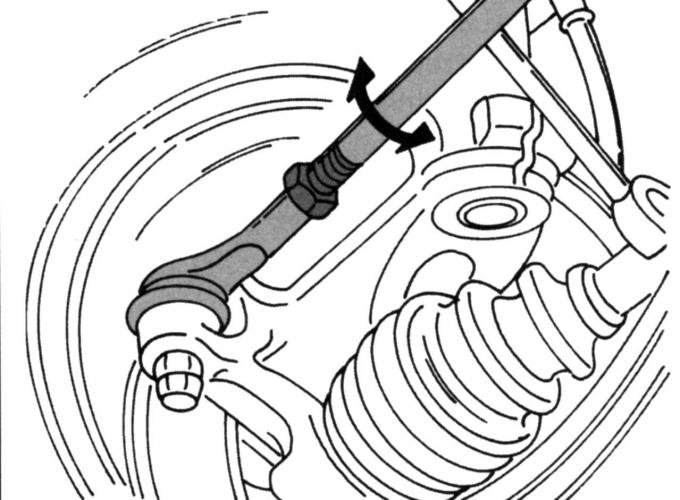
Fig. 207. Direction of rotation of the transverse steering rods when adjusting the wheel alignment
- adjust the length of both tie rods by turning them left or right, as indicated by the arrow in Fig. 207;
- the adjustment is performed in several attempts (adjust the transverse steering rods on both sides in the same direction, by the same number of turns), only by repeated measurements can the desired value be achieved. After adjustment, tighten the lock nuts 1 (see Fig. 206) to a torque of 41 N·m and again secure the steering gear cuffs with clamps 2.