To remove the shock absorber strut without the rest of the suspension parts, proceed as follows:
- loosen the wheel nuts, jack up the car and remove the wheel;
- remove the brake pipe fastening elements from the shock absorber strut (two bolts);
- unscrew the disc brake caliper and tie it securely to the front suspension with wire so that it does not hang on the brake hose;
- Disconnect the plug connector if a brake lining wear indicator is installed;
- disconnect the ball joint of the transverse steering rod from the steering knuckle arm;
- if there is ABS, remove the wheel speed sensor (one bolt);
- disconnect the anti-roll bar link;
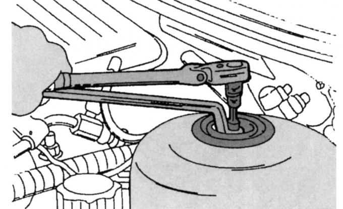
Fig. 202. Unscrewing the upper stop of the shock absorber strut
- unscrew the upper stop of the shock absorber strut, for which insert a key with an internal Allen key "8 mm" into the piston rod and unscrew the nut with a socket head, as shown in Fig. 202;
- Loosen the clamping bolt on the rear of the shock absorber strut and use a strong screwdriver to open the clamping slot of the steering knuckle while simultaneously pressing down on the wishbone together with the steering knuckle so that the rear of the shock absorber strut comes out of the steering knuckle (do not press too hard to avoid damaging the constant velocity joints of the drive shaft);
- if the car is equipped with an electronic suspension adjustment device, then an additional wire is connected to the shock absorber strut, disconnect it from the wire mounting bracket, then disconnect the plug connector;
- remove the shock absorber strut from underneath the car.
If it is necessary to remove the shock absorber strut assembly, work only on the right side, since the left control arm can only be disconnected after the subframe has been removed. In this case, follow the relevant descriptions for removing the drive shaft, control arm, etc.
Installation is carried out in the reverse order of removal, taking into account the following:
- connect the shock absorber strut to the steering knuckle, insert the clamp bolt and tighten to 85 Nm;
- insert the upper safety stop, tighten the nut as shown in Fig. 202, to a torque of 46 N·m;
- secure the rear wishbone to the subframe (only the right side when the shock absorber strut is completely removed);
- connect the transverse steering rod, tighten the nut to a torque of 37 Nm;
- connect and tighten the anti-roll bar mount to a torque of 50 Nm;
- connect the brake hose, in this case bleed the brake system as described in the relevant section, otherwise connect the hose holder (50 Nm);
- connect the ball joint of the wishbone to the steering knuckle, if it was removed, and tighten the bolt to a torque of 85 N·m;
- if necessary, install the wheel speed sensor (ABS) and tighten the sensor mounting bolt to 10 Nm (this also applies to the electronic suspension controller plug connector - insert it and secure the wire);
- tighten the disc brake caliper and tighten the bolts;
- insert the plug connector of the brake lining wear monitoring device (if available);
- check that the brake hose does not twist (stretch) when turning the wheels;
- lower the vehicle onto its wheels and tighten the wheel nuts to a torque of 85 Nm.
Spare parts for shock absorbers may have different numbers, so they should be ordered only from the corresponding spare parts catalogs.
This article is a copy from the website FORDBOOK.RU