- МkPherson shock absorber struts with coil springs, which are installed between two support cups of the suspension;
- double-acting hydraulic shock absorbers;
- triangular wishbones.
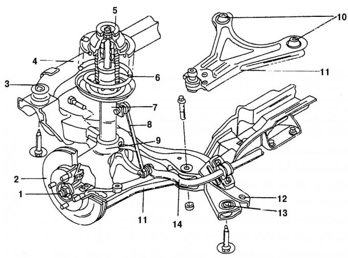
Fig. 185. Front suspension assembly: 1 — wheel drive shaft nut; 2 - brake disc; 3 - Front rubber bushing; 4 — subframe; 5 - Upper shock absorber bearing; 6 - coil spring; 7 — shock absorber strut; 8 — anti-roll bar link; 9 — steering knuckle; 10 - rubber-metal bearing; 11 — transverse lever; 12 - guide hole for subframe alignment (on both sides); 13 - rear rubber bushing; 14 — anti-roll bar
The anti-roll bar is attached to the subframe and is connected to the upper parts of the shock absorber struts on the left and right by means of a system of rods and levers. The steering knuckles are attached to the transverse levers. Two nuts and two bolts are used for this, tightened through vertically located bushings. On the underside of the steering knuckle is a replaceable ball joint, which is designed to connect the transverse lever to the steering knuckle. Fig. 185 shows the front suspension, which is equipped with most models. The model with an engine capacity of 200 hp differs in the design of the transverse lever, which is shown in Fig. 186.
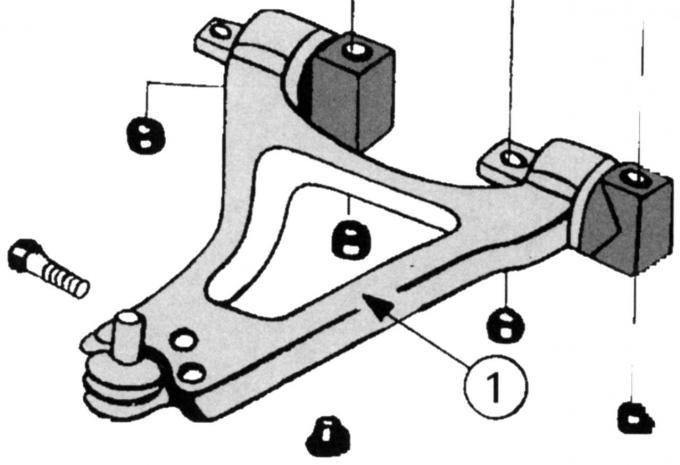
Fig. 186. Wishbone on a car with a V6 engine (200 hp)
The shock absorber strut consists of a coil spring and a telescopic shock absorber inserted into the spring. The internal stops of the shock absorber strut limit the amount of return travel. In the case of severe elastic deformations, such as when hitting a pothole in the road, a similar stop limiter comes into effect. The shock absorber struts are held at the top by support elements attached to the body. To prevent contamination, the strut is protected by a cuff. The rubber buffer of the shock absorber strut prevents the breakdown of the wheel suspension in a compressed state.
The shock absorber strut has a support (in the engine compartment). On top, it is made in the form of a rubber support (cushion), which, inserted through the centering ring, rests on the top and bottom of the plate disks. The piston rod of the shock absorber strut is screwed into the rubber support. The support is attached to the body using a nut.
The steering knuckle (like a hub) holds the lower end of the strut by means of a clamping bolt. The steering knuckle is connected to the transverse arm by a ball joint. The journal of the latter is firmly clamped in the transverse arm. The transverse arm enters the load-bearing beam of the bridge, can move in it and takes on the resulting lateral forces. In addition, the steering knuckle is also designed to fasten the shock absorber strut, as well as the steering knuckle arm to the end of the transverse steering rod.
The transverse stabilizer, or anti-roll bar, is attached to the underbody of the car by rubber bushings and is connected to the shock absorber struts on the left and right by means of a connecting rod (connecting rod). It reduces lateral tilt when cornering.
The rack-and-pinion steering mechanism is located behind the engine and is attached to the cross frame. The steering rods are attached to the toothed rack on the left and right. If the steering wheel, which is connected to the steering mechanism via a two-link steering shaft, rotates, this movement is transmitted to the steering knuckle lever and, consequently, to the wheels.
Most suspension repairs require special tools. If you don't have them or you're not completely confident that you can do the repairs yourself, contact a specialized service station.
(For more information, please visit the website: «Fordbook.ru»)