Remove the left transverse suspension arm as follows:
- disconnect the battery;
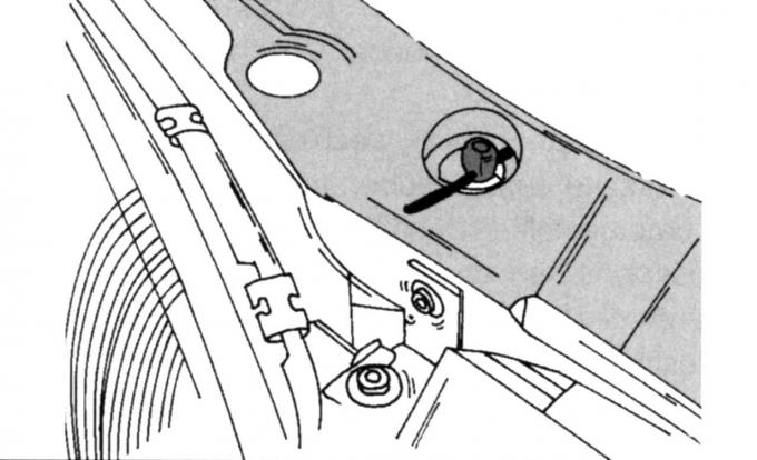
Fig. 161. Radiator fastening
- insert pins on both sides of the radiator (see Fig. 161) to prevent it from falling;
- Loosen the wheel nuts and jack up the front of the car;
- remove the front wheels to make it easier to access the wishbone;
- remove the reflector under the radiator (fastened with bolts and clamps);
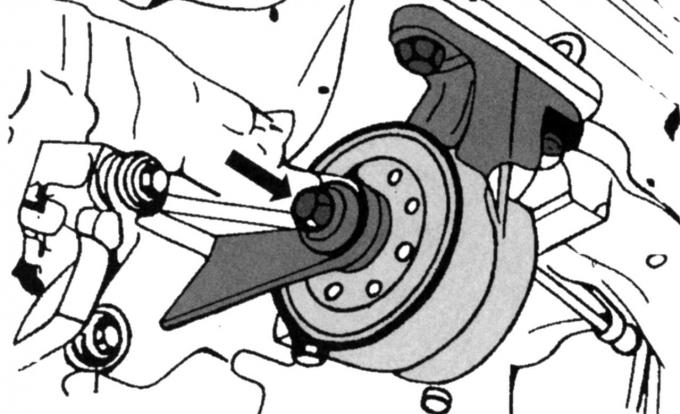
Fig. 194. Location of the rear bearing on a vehicle with a manual transmission
- on vehicles with a manual transmission, unscrew the middle bolt of the rear bearing, the location of which is shown in Fig. 194; on vehicles with an automatic transmission, unscrew the two bolts located below;
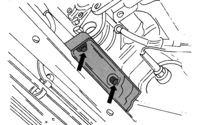
Fig. 195. Removing the front suspension support element
- unscrew all the front suspension bolts (Fig. 195);
- if there is air conditioning, remove the condensate tank (two bolts);
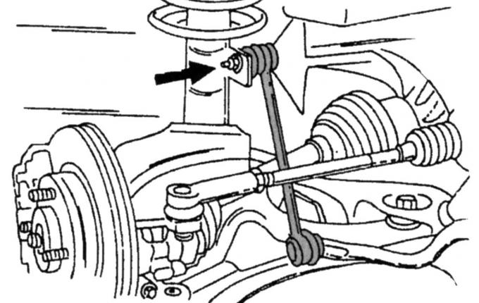
Fig. 196. Location of the connection of the anti-roll bar link to the shock absorber strut
- unscrew the stabilizer rod in the place shown in Fig. 196 in front of the shock absorber strut;
- holding the ball joint clamp bolt from the rear, unscrew the nut and knock out the bolt;
- insert a screwdriver into the slot and press down on the wishbone so that the ball joint pin disengages from the steering knuckle, while trying not to damage the rubber cuff of the ball joint;
- similarly disconnect the stabilizer and the wishbone on the other side;
- unscrew the protective shield under the crankshaft;
- mark the exact position of the subframe and unscrew the four bolts (two at the top and two at the bottom) on the outer sides, while the frame should rest on the jack, since after unscrewing the bolts it may fall;
- lower the frame to gain access to the wishbone mounting bolts;
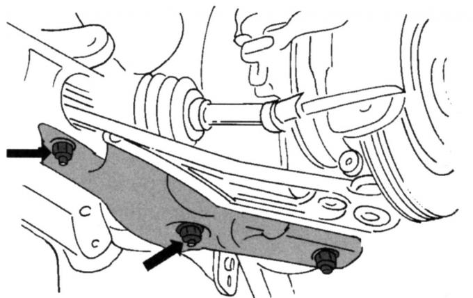
Fig. 197. Location of the bolts for fastening the left transverse suspension arm (except for the 200-horsepower model)
- on all vehicles, except for vehicles with a 200 hp engine, you can now unscrew the bolts securing the left and, if necessary, the right wishbone (both bolts with nuts are located in the places shown in Fig. 197; on cars with a 200 hp engine, the wishbone is secured with four bolts and nuts, which can also be unscrewed from below);
- remove the transverse arm.
Replace the rubber bushings of the transverse arm if they have been knocked out. Since the bushings can only be installed in the correct position with a special tool, take the transverse arm to a specialized service station.
Install the removed parts in the reverse order. Align the subframe in a free state.
Install the left suspension arm as follows:
- install both wishbones on the subframe and insert the bolts from above; hold the bolt heads and tighten both nuts to 50 Nm, then mark the position of the nuts and tighten another quarter turn (the bushings should be pre-tensioned as per the instructions);
- on a car with a 200 hp engine, tighten the nuts in the following order: both large nuts are tightened to 115 Nm, both small nuts - 70 Nm (angular tightening is not required);
- install the subframe in the correct position using a jack, align it according to the marks and tighten the four bolts to a torque of 135 N·m;
- install the ball joint of the rear wishbone into the steering knuckle (if necessary, slightly open the clamping spline), insert the bolts and tighten the connection to a torque of 85 N·m;
- install the rear torque stop (powertrain stop), tightening the long and middle bolts to 120 Nm (cars with a manual transmission), and the bolts inserted from below to 48 Nm;
- put the car on its wheels and tighten the wheel nuts.
Further assembly is carried out in the reverse order of removal.
For more information, please visit the website: fordbook