Remove the right wishbone as follows:
- loosen the shock absorber piston rod mounting nut by 5 turns;
- loosen the wheel nuts, place the car on a secure support and remove the wheel;
- remove the reflector in the rear area of the drive belt (one bolt on the left and right);
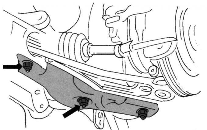
Fig. 197. Location of the bolts for fastening the left transverse suspension arm (except for the 200-horsepower model)
- unscrew the nuts and bolts on the inner side of the transverse arm, shown in Fig. 197, to disconnect the independent suspension arm (on vehicles with a 200 hp engine, unscrew the four bolts and nuts from below, shown in Fig. 198);
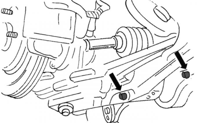
Fig. 198. Fastening the rear transverse arm on vehicles with a 200 hp engine.
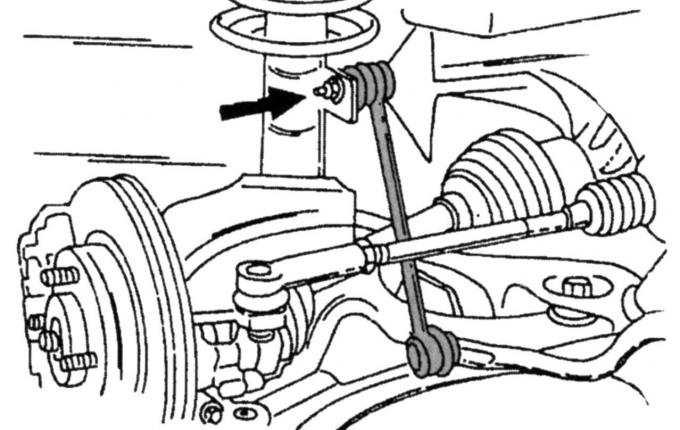
Fig. 196. Location of the connection of the anti-roll bar link to the shock absorber strut
- unscrew the stabilizer bar rod as shown in Fig. 196, turn the rod and move it to the side;
- unscrew the tie rod joint from the steering knuckle arm and press it with a puller (replace the cotter pin);
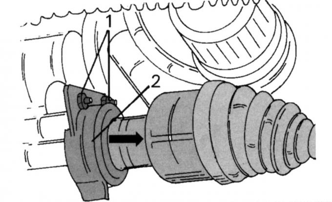
Fig. 30. Removing the right wheel drive shaft: 1 — thrust ball bearing screw; 2 - heat shield
- disconnect the drive shaft from the gearbox by unscrewing both nuts of the intermediate bearing (see Fig. 30), remove the heat-insulating shield and take out the shaft;
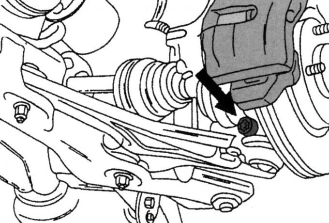
Fig. 199. Fastening the transverse arm of the ball joint on the rear side of the steering knuckle
- unscrew the ball joint mounting bolt of the wishbone on the rear side of the steering knuckle, as shown in Fig. 199, press the wishbone down with a tire iron and remove it as soon as it is released (do not damage the protective cover of the ball joint).
If necessary, the rubber bushings can be replaced.
Perform installation in the following order:
- install the wishbone from the rear: insert both bolts from above and tighten the nuts to 50 Nm, then turn the nuts 90° (a quarter turn); on cars with a 200 hp engine, tighten the two small nuts and bolts to 70 Nm, and the large ones to 115 Nm;
- install the drive shaft according to Fig. 30, tighten both intermediate bearing nuts to a torque of 27 Nm, reinstall the heat-insulating shield;
- connect the wishbone to the steering knuckle, tighten the clamp bolt to 84 Nm;
- connect the tie rod joint to the steering knuckle and tighten the nut to a torque of 37 Nm (replace the self-locking nut);
- connect the anti-roll bar link and tighten the nut to a torque of 50 Nm;
- tighten the nut in the middle of the shock absorber strut stop to a torque of 46 Nm, the nut does not need to be replaced, since it was not completely unscrewed;
- install the wheel, lower the car to the ground and tighten the wheel nuts to a torque of 85 Nm.
Information for this article was taken from the website [Fordbook.ru]