Models since 9/94
Removal
Mark the position of the front wheel on the hub with paint. This will allow the balanced wheel to be installed again in its previous position. When loosening the wheel mounting nuts, the car must be on the platform. Raise the front of the car onto the support jacks and remove the front wheel.
Loosen the locking bolt nut for the ball joint of the control arm at the pivot bearing and remove the locking bolt.
Pull the wishbone ball joint pin out of the pivot bearing with a downward movement.
Caution: Make sure that the rubber seal of the ball joint is not damaged. Wrap the ball joint with a rag.
Loosen the bolts at the wishbone supports and remove the wishbone.
Installation
Tighten the bolts at the wishbone supports.
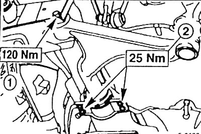
Caution: Bolts "1" and "2" should only be fully tightened after the vehicle is standing on its wheels.
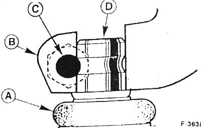
Models from 9/94: Press the ball joint of the control arm from below into the pivot support "B" until it stops. Insert bolt "C" from the front side; it must pass through the groove on the journal "D" of the ball joint of the control arm.
Note: The bolt head must face the direction of vehicle movement. Tighten the new self-locking nut of the bolt to 80 Nm, A - dust seal.
Place the front wheel so that the marks made before removal match. First apply a thin layer of plastic grease for rolling bearings to the place where the rim fits on the wheel hub. Do not lubricate the threads of the wheel studs. Tighten the wheel with nuts. Lower the car and tighten the wheel mounting nuts crosswise to a torque of 100 Nm.
Place the car over an inspection pit or on an overpass.
The vehicle must stand on its wheels. Tighten support bolt "1" to 120 Nm, and tighten mounting bolts "2" to 25 Nm, see Figure F-3692 above.
If possible, check the chassis parameters immediately and, if necessary, adjust them, see p. 109.