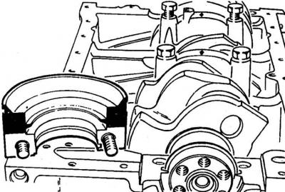
Identification of main and connecting rod bearing caps
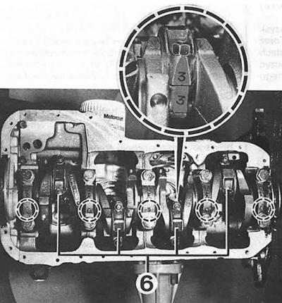
1–5 – main bearing caps (designations in circles),
6 – connecting rod bearing caps, the circle shows an enlarged designation of the connecting rod base and cap
Fastening the front covers
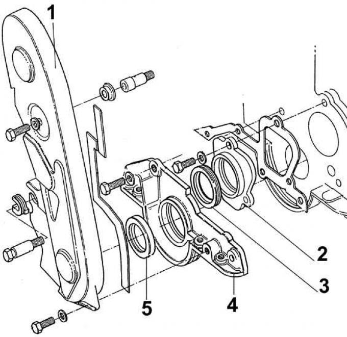
1 – belt cover, 2 – intermediate shaft cover, 3 – intermediate shaft sealing ring, 4 – front engine block cover, 5 – front crankshaft sealing ring
Gas distribution system
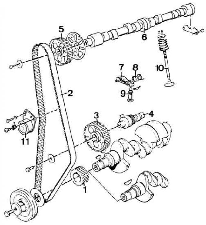
1 – crankshaft pulley, 2 – timing belt, 3 – intermediate shaft pulley, 4 – intermediate shaft, 5 – camshaft pulley, 6 – camshaft, 7 – valve lever, 8 – valve lever spring, 9 – ball-head bolt (valve lever support), 10 – valve, 11 – timing belt tensioner
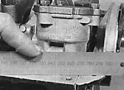
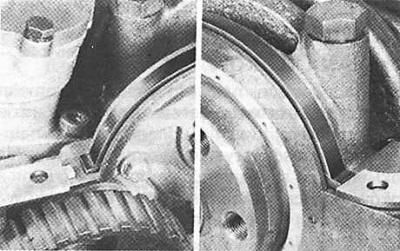
Checking the alignment of the back cover
Sealing compound application areas (black) on rear main bearing cap
Connecting rod weight marking
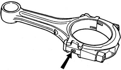
The marking is indicated by an arrow.
Relative position of the arrow on the piston bottom and the oil splash hole on the connecting rod
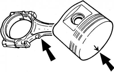
The location of the arrow on the piston crown and the oil splash hole on the connecting rod are indicated by arrows.
1. Install the clutch shaft bearing into the hole in the rear of the crankshaft (tool 21.044).
2. Insert dry main bearing shells into the sockets in the cylinder block.
3. Lubricate the working surfaces of the half-liners with oil and install the crankshaft on them.
4. Install the main bearing caps together with the oiled half-shells (see Fig. Identification of the main and connecting rod bearing caps). The arrows on the main bearing caps should point towards the pulley on the crankshaft).
5. Tighten the main bearing cap bolts to the specified torque and measure the crankshaft end play.
6. Install a new rear crankshaft seal ring using tool 21.011 A.
7. Coat the groove of the rear crankshaft seal cover with sealing paste (No. A 70 SX-19554-BA) and install the two gasket halves using a screwdriver with a blunt blade; the red marking on the gasket must face the bearing cap.
8. Install the front cylinder block cover with a new gasket.
9. Install a new front sealing ring (tool 21.009 A).
10. Attach the intermediate shaft and its thrust bearing to the cylinder block; install the cover with a new sealing ring.
11. Install the flywheel on the crankshaft, tightening the flywheel mounting bolts (lubricate the threads with oil) to the appropriate torque.
12. Using tool 21.044, center the clutch disc on the flywheel and install the clutch drive part.
13. Lubricate the cylinders and pistons with oil, with piston rings installed correctly.
14. Install the piston-connecting rod units in the cylinders, compressing the piston rings with a special device. Point the arrows on the pistons toward the valve timing system.
15. Install the connecting rod bearings and connecting rod caps, tightening the bolts to the appropriate torque. Check the axial play of the connecting rods on the connecting rod journals.
16. Install the oil pump drive shaft and screw on the oil pump together with the oil supply lines.
Caution! When installing a new pump, fill it with oil and turn its drive shaft by hand several times.
17. Install new gaskets (lubricated with sealing paste) into the grooves of the front (left picture) and rear (right picture) crankshaft main bearing caps, insert new oil pan gaskets and press them into the grooves.
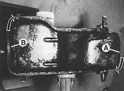
18. Install the oil pan and tighten its bolts in three stages, starting with bolt (A), towards bolt (B), and then from bolt (B) to bolt (A).
19. Install the fuel pump drive pusher and the fuel pump with the gasket.
20. Install the oil sump (secure it with Loctite).
21. Install the coolant pump.
22. Install the oil filter together with the gasket. The oil filter housing should be tightened by hand until it touches, and then another 3/4 turn.
23. Screw in the oil pressure sensor.
24. Install the pulley on the crankshaft (with the reinforced side facing the flywheel).
25. Screw into the cylinder block in place of bolts No.7 and 9 (see Fig. Cylinder head bolt tightening sequence), pins centering the cylinder head (see subsection 3.1.2.2.4). Install the cylinder head gasket with the inscription facing up.
26. Set the piston in the 1st cylinder at top dead center (TDC) and the camshaft pulley so that the timing marks are aligned (see Fig. Installation signs of the gas distribution system).
27. Install the cylinder head, insert (except bolts No.7 and 9) and slightly tighten the head bolts, remove the bolt centering pins and screw in the remaining two bolts in their place. Tighten the cylinder head mounting bolts accordingly.
28. Install the pulley (with the concave side facing out), the toothed belt and its casing on the crankshaft.
29. Install the flexible cooling system pipes and adjust the timing belt tension.
Caution! From now on, the crankshaft should only be rotated in the direction of its rotation while the engine is running.
30. Adjust the position of the generator, install the coolant pump and fan.
31. Install the generator pulley and tighten the V-belt so that its deflection is 10 mm.
32. Check whether the piston of the 1st cylinder is set to the TDC position and install the ignition distributor.
33. Connect the vacuum line to the ignition system.
34. Check and, if necessary, adjust the valve clearance.
35. Install the cylinder head cover, paying attention to the correct position of its gasket.
36. Tighten the cylinder head cover mounting bolts in the appropriate sequence (see Fig. Cylinder Head Cover Bolt Tightening Sequence).
37. Screw the spark plugs into the cylinder head and connect the high-voltage wires.
38. Insert a new gasket and screw the drain plug into the oil pan.
39. Connect the flexible crankcase ventilation hose.
40. Insert the oil level indicator into the hole in its guide in the engine cylinder block.
This article is a copy from the website: Fordbook.ru