ONS engine components
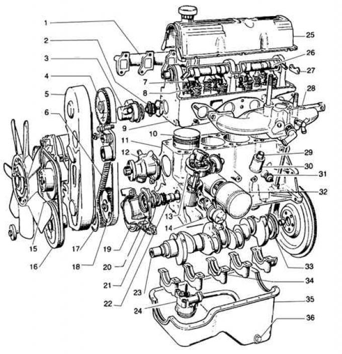
1 - exhaust manifold, 2 - thermostat, 3 - thermostat housing, 4 - camshaft sprocket, 5 - toothed belt guard, 6 - toothed belt, 7 - lever, 8 - valve spring, 9 - cylinder head, 10 - piston, 11 - engine block, 12 - coolant pump, 13 - ignition distributor, 14 - fuel pump, 15 - V-belt, 16 - V-belt pulley on the crankshaft, 17 - toothed pulley on the crankshaft, 18 - toothed pulley on the intermediate shaft, 19 - crankshaft front cover, 20 - intermediate shaft front cover, 21 - intermediate shaft thrust plate, 22 - intermediate shaft, 23 - crankshaft, 24 - oil pump, 25 - cylinder head cover, 26 - camshaft, 27 - camshaft thrust plate, 28 - intake manifold, 29 - crankcase ventilation breather, 30 - oil separator, 31 - oil pressure sensor, 32 - oil filter, 33 - crankshaft rear oil seal, 34 - crankshaft thrust half ring, 35 - oil sump, 36 - oil drain plug
Elements of fastening of a cover of a head of the block of cylinders (old type)
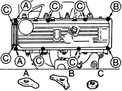
A, B - pressure plates,
C - oil gasket
Elements of fastening of a cover of a head of the block of cylinders (new type).
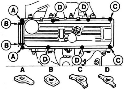
A, B, C, D - pressure plates
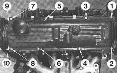
Tightening order for cylinder head cover bolts
Checking valve clearances
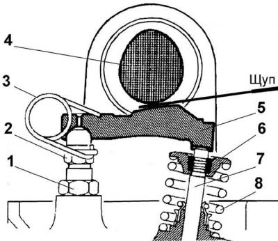
1 - locknut, 2 - adjusting bolt, 3 - spring, 4 - cam, 5 - pusher (lever arm), 6 - plate, 7 - valve, 8 - valve spring
Valve clearance adjustment
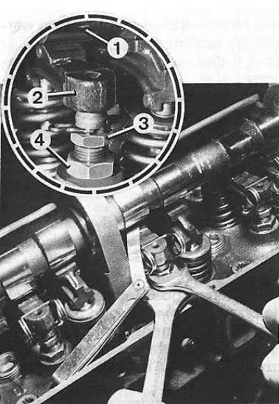
1 - cam, 2 - valve lifter, 3 - adjusting bolt, 4 - lock nut
Checking and adjusting the valve clearance is carried out on a cold engine.
Valve clearance adjustment
1. Remove the air filter, mark and disconnect the high voltage wires from the ignition distributor and spark plugs.
2. Remove the cylinder head cover by unscrewing the ten bolts of its fastening (in the reverse order shown in Fig. Tightening order for cylinder head cover bolts).
3. Unscrew the spark plugs to make it easier to turn the engine crankshaft.
4. Rotate the crankshaft (in the direction of its working rotation) until the cam of the valve under test is set upwards.
5. Using a feeler gauge, check the clearance between the tappet and cam of this valve (see fig. Checking valve clearances). The clearance measured with the engine cold between the valve stem and its tappet should be 0.20 mm for the intake valve and 0.25 mm for the exhaust valve.
6. If necessary, adjust the valve clearance by unscrewing the locknut and turning the valve clearance adjustment bolt accordingly (3) (see fig. Valve clearance adjustment).
7. Similarly, check and, if necessary, adjust the clearances of the remaining valves.
8. After checking and adjusting the valve clearances, install the head cover with a new gasket and tighten the ten cylinder head cover bolts to the appropriate torques in the order shown in fig. Tightening order for cylinder head cover bolts.
9. Screw in new spark plugs.
10. Connect the high voltage wires to the ignition distributor and spark plugs.
11. Install the air filter.
Visitor comments