Contents: Disassembly ↳ Checking the valve guides ↳ Processing of valve seats in the… ↳ Lapping ↳ Assembly ↳
Longitudinal fixation of the camshaft
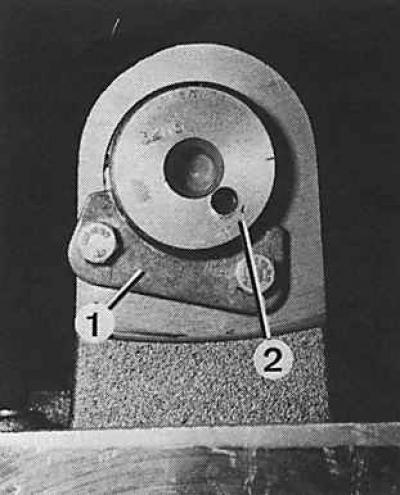
1 – mounting plate,
2 – camshaft
Disassembly
1. Place the cylinder head in the front and rear parts on two wooden blocks.
2. Remove the intake manifold together with the carburetor and coolant drain pipe.
3. Unscrew the thermal jacket and then the exhaust manifold.
4. Unscrew the mounting studs of both manifolds.
5. Unscrew the coolant temperature sensor.
6. Remove the oil supply pipes to the camshaft bearings.
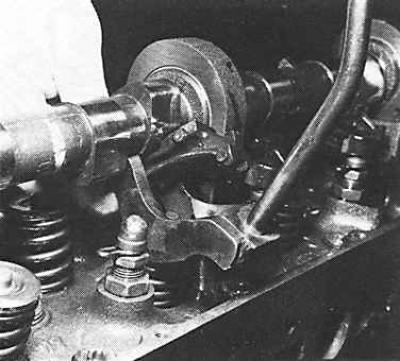
7. Remove (tool 21.005 A) the valve lever springs and valve levers in order.
8. Compress the valve springs in order (device 21.005 A), remove the crackers securing the upper spring retaining plate. Remove the upper plate and valve spring, paying attention not to damage the valve stems.
9. Remove the pulley from the camshaft, holding the camshaft with a flat wrench by the grooves behind the sixth cam. Remove the camshaft pulley thrust gasket, as well as its sealing ring.
10. Unscrew the two mounting plate bolts at the rear of the camshaft and carefully pull the camshaft back. Unscrew the bolts that form the stop for the valve lever, ending in ball ends (see the figure in item 7); if they are to be used later, they should be marked so that during assembly they are installed in the same places and can interact with the same valve levers.
11. Unscrew the timing belt tensioner (tool 21.012) and remove the spacer sleeve.
Checking the valve guides
Worn valve guides do not ensure coaxial installation of the valves in the seats, which leads to a significant increase in fuel and oil consumption.
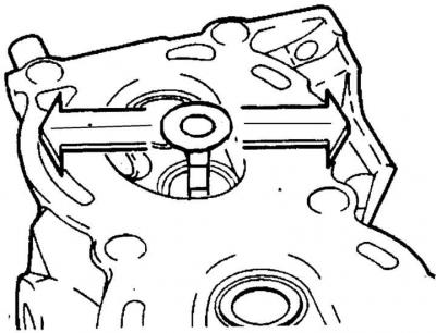
1. Insert the valve into the guide bushing and, moving the valve in the transverse direction, check the clearance.
2. If the clearance exceeds the permissible norms, it is necessary to process the guide bushing using the appropriate reamer to the nearest increased size. Processing of the guide bushing must begin from the combustion chamber side.
3. If the guide bushings have been machined, valves with larger diameter stems must be installed.
Processing of valve seats in the cylinder head
Valve seats with signs of wear or burning must be processed with mandatory preservation of the angles and size of the chamfer. Otherwise, it is necessary to replace the cylinder head. After any processing of the valve seats, it is necessary to grind the valves.
Lapping
When grinding valves, use only fine-grained polishing paste.
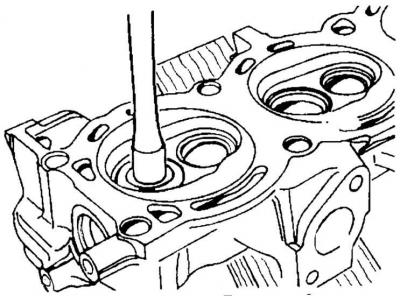
1. Lubricate the surface of the valve seat with a small amount of paste and install the valve in the corresponding seat. Press the rubber suction cup tightly to the valve plate and rotate the valve in one direction or the other.
2. After finishing the grinding process, thoroughly clean all parts from dirt and paste and check the valve seat and plate. A solid matte ring should be visible on both parts, which indicates the width of the valve chamfer.
Assembly
1. Screw in the manifold mounting studs, and then the coolant temperature sensor.
2. Lubricate the camshaft journals, cams and thrust surfaces, inner surfaces of the bearing rings, ball ends of the valve lever stop bolts, and the surfaces of the valve lever that interact with the camshaft cams with SAE 80/90 class hypoid gear oil.
3. Insert the camshaft from behind the cylinder head until its journals are installed in the bearing rings, paying attention not to damage the sliding surfaces.
4. Tighten the bolts that support the valve lever and the nuts that prevent them from loosening.
5. Lubricate the valve stems and valve guides with SAE 80/90 hypoid gear oil. Insert the valves and tape the cracker mounting locations.
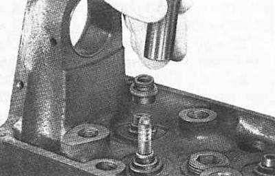
6. Lubricate the valve stem seals with engine oil, insert them and remove the adhesive tape from the valve stems.
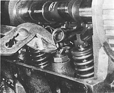
7. Insert the valve springs and upper plates in order. Compress the springs and insert the crackers.
8. Install the valve levers.
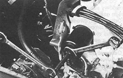
9. Lubricate and install a new front camshaft bearing seal ring (tool 21.009 A).
10. Place the thrust pad and pulley (reinforced side out) onto the camshaft.
11. Install the valve lever retaining springs and adjust the valve clearance.
12. Install the spacer sleeve, timing belt cover and tensioner.
13. Screw the oil supply line to the camshaft bearings, the coolant outlet chamber from the cylinder head, and the thermostat (new gasket).
14. Place a 5 mm sealing cord (A 70 SX 19554-BA) on the intake manifold gasket, install new exhaust manifold gaskets and screw on both manifolds.
15. Screw on the exhaust manifold heat shield.
Attention! If previously used valves are installed in a new cylinder head, proceed as follows:
- grind the valves and their seats;
- thoroughly clean off any paste remaining after grinding, lubricate the valve stems with oil and then proceed with assembly.
(For more information, please visit the website: fordbook)