Lubrication system
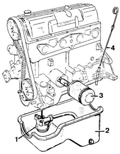
1 - oil pump, 2 - oil pan, 3 - oil filter, 4 - oil level gauge
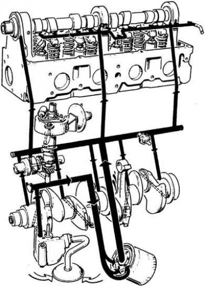
Engine lubrication circuit
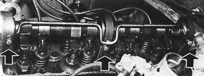
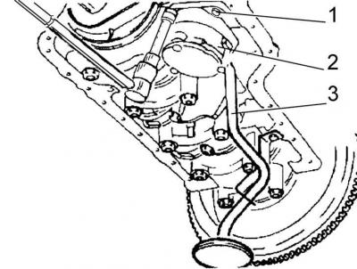
Installing the oil supply pipe to the camshaft bearings
The oil pump draws engine oil from the crankcase and pressurizes it through a short passage to a full flow oil filter. The safety valve located in the pump regulates the maximum pressure generated by the pump. When the pressure created by the pump is exceeded, the valve opens and bypasses oil into the crankcase. The purified oil through the filter enters the main oil line. In the event of a clogged filter, the pressure reducing valve opens and part of the oil, without purification, is sent to the main line.
From the main line, oil flows through five small channels to the crankshaft main journals. Through diagonal holes in the crankshaft, oil enters the connecting rod journals and is then sprayed onto the cylinder walls.
From the main line, oil flows to the intermediate shaft and then to the ignition distributor. At the same time, engine oil is supplied directly to the camshaft bearings through three oil lines. From the middle bearing, through the oil spray lines, oil is supplied to all cams and levers.
Oil pressure check
1. Warm up the engine to normal operating temperature.
2. Disconnect the electrical wire from the oil pressure warning light sensor and unscrew its sensor (in vehicles equipped with an oil pressure gauge, disconnect the fitting of its pipeline).
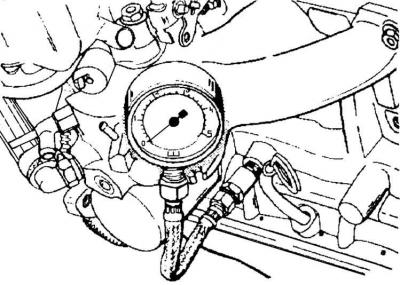
3. Screw a control pressure gauge into the hole in the cylinder block.
4. Start the engine and check the oil pressure at idle speed and above 2000 rpm. The oil pressure must be at least 100 kPa, but not more than 500 kPa.
5. Unscrew the pressure gauge and screw in the oil pressure indicator light sensor.
Oil filter replacement
1. Unscrew the oil filter from the cylinder block.
2. Lubricate the gasket surface of the new oil filter with oil.
3. Screw in the oil filter until the gasket touches the surface of the cylinder block. Then tighten the filter by hand an additional 3/4 turn.
Oil pump repair
Oil pump mount
1 - pump mounting bolts, 2 - pump, 3 - oil receiver tube
Oil pump
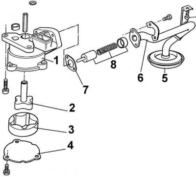
1 - housing, 2 - outer gear, 3 - inner gear, 4 - cover, 5 - oil receiver mesh, 6 - oil receiver tube, 7 - gasket, 8 - safety valve
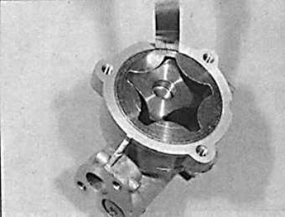
Checking clearance between outer rotor and oil pump housing
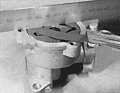
Checking the axial play of the oil pump rotor
Attention! The oil pump gears are matched in pairs and both gears should be replaced if necessary.
1. Apply to the back surface of the outer gear (greater) a sign for its installation in the same position relative to the internal gear (lesser) during the assembly process, in which it was removed from the factory packaging.
2. Remove the engine oil pan.
3. Remove the oil pump by unscrewing the three bolts securing the pump to the cylinder block.
4. Remove the oil pump cover and remove the gears, and remove the oil supply pipe to the pump.
5. Punch a hole in the middle of the rubber plug on the pump bypass valve.
6. Remove the rubber plug with a bolt of the appropriate diameter.
7. Remove the spring and bypass valve piston.
8. Insert both gears into the pump housing, observing their correct relative position.
9. Using a ruler and a feeler gauge, measure the gap between the plane of the pump housing and the rear planes of the gears. If it exceeds the maximum allowable value, the pump housing must be replaced.
10. Use a feeler gauge to check the clearance between the outer gear and the pump housing. If it exceeds the maximum allowable value, the pump housing must be replaced.
11. Lubricate parts of the bypass valve with engine oil and install the bypass valve.
12. Install the bypass valve rubber plug with the flat side facing out. It should be on the edge of the sealing surface of the oil supply pipe to the pump.
13. Lubricate both pump gears with engine oil.
14. Install the oil pump cover and tighten its bolts to the correct torque.
15. Insert the shaft that transmits the drive from the intermediate shaft (the end with an asymmetrical protrusion must be directed towards the ignition distributor), into the pump drive shaft and, turning it by hand, make sure that the pump gears interact without jamming.
16. Install the gasket and oil supply line to the pump.
17. Install the oil pump to the cylinder block, tightening the mounting bolts to the correct torque.
18. Attach the oil pan to the cylinder block.
Visitor comments