You will need: all the tools needed to remove the battery (see "Removing and installing the battery") and its shelves (see "Removing and installing the battery mounting shelf"), cylinder head covers (see "Replacing the cylinder head cover gasket"), timing belt of the gas distribution mechanism (see "Replacing the timing belt"), camshafts (see "Replacing camshafts"), collector (see "Removing, installing the exhaust manifold and replacing its gasket"), as well as TORX T25 and T55 keys, a flat-blade screwdriver, pliers, and side cutters.
1. Reduce the pressure in the fuel system (see "Losing pressure in the fuel system").
2. Remove the battery (see "Removing and installing the battery").
3. Remove the battery tray (see "Removing and installing the battery mounting shelf").
4. Drain the fluid from the engine cooling system (see "Replacing the coolant").
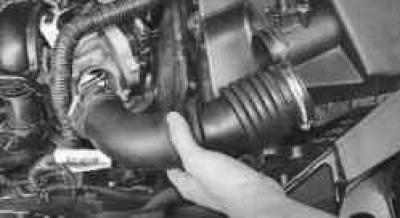
5. Remove the air supply hose (see "Removing and installing the air filter and intake silencer").
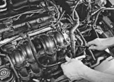
6. Remove the crankcase ventilation system pipe (see "Cleaning the crankcase ventilation system").
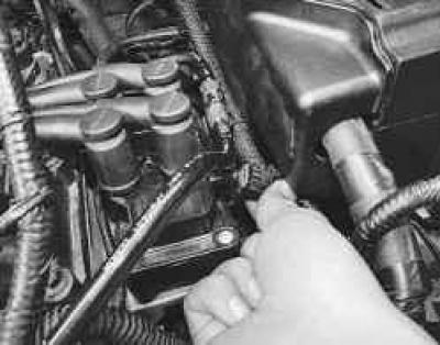
7. Squeeze the clips and disconnect the wiring harness connector from the ignition coil.
8. Remove all spark plugs (see "Replacing and servicing spark plugs").
9. Remove the cylinder head cover (see "Replacing the cylinder head cover gasket").
10. Remove the timing belt (see "Replacing the timing belt").
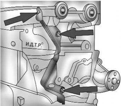
Fig. 5.5. Rear cover of the timing belt
11. Unscrew the three bolts securing the rear timing belt cover (Fig. 5.5) and remove it.
12. Remove the camshafts (see "Replacing camshafts").
13. Remove the catalytic converter (see "Removing, installing the exhaust manifold and replacing its gasket").
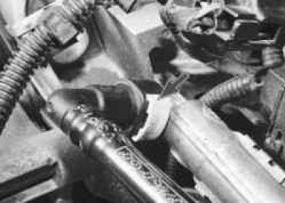
14. Disconnect the fuel supply line from the fuel rail by squeezing the clamps of the connecting sleeve.
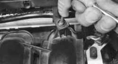
15. Remove the two screws securing the fuel supply line holders and move the line to the side.
16. Remove the injector electrical connector rail (see "Removing and installing the fuel rail").
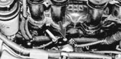
17. Remove the screw securing the oil level indicator bracket.
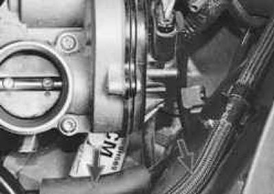
18. Disconnect the brake booster and purge valve hoses from the intake pipe.
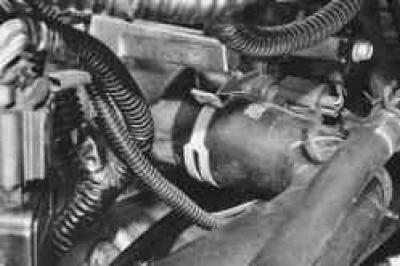
19. Using pliers, squeeze the clamps and slide them along the hoses, disconnect the radiator hose from the water jacket outlet pipe…
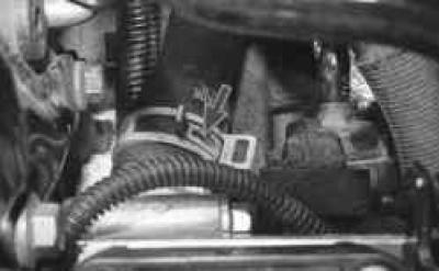
20. …and the interior heater hose.
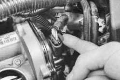
21. Slide the lock up…
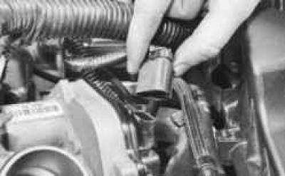
22. …and disconnect the wiring harness connector from the throttle body cover.
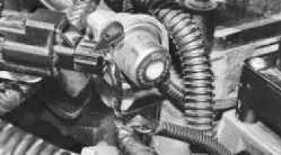
23. Squeeze the retainer and disconnect the wiring harness connector secured to the cylinder head bracket.
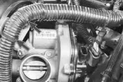
24. Use side cutters to cut the plastic ties securing the wiring harness to the cylinder head bracket.
NOTE: Clamps are single use. Install new clamps during assembly.
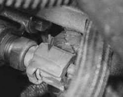
25. Press the lock and disconnect the wiring harness connector from the coolant temperature sensor.
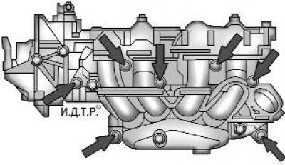
Fig. 5.12. Intake manifold mounting bolts
26. Remove the two lower bolts securing the intake pipe (see Fig. 5.12).
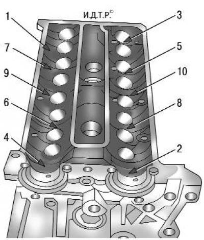
Fig. 5.6. Procedure for loosening the cylinder head bolts
27. Loosen the ten cylinder head mounting bolts in the order shown in Fig. 5.6, then completely unscrew the head mounting bolts and remove them together with the washers.
WARNING: The cylinder head bolts may only be removed when the engine is cold.
28. Remove the cylinder head assembly with the intake pipe and throttle assembly and the gasket installed underneath.
USEFUL TIP: It is easier to remove the cylinder head with an assistant, as it is quite heavy.
29. Clean the mating surfaces of the head and block.
30. Check the cylinder head for warpage. To do this, place a ruler edgewise on the surface of the head, first in the middle along, then across and diagonally, and measure the gap between the plane of the head and the ruler with a feeler gauge. Replace the cylinder head if the gap is greater than 0.1 mm.
31. Install the cylinder head in the reverse order of removal, taking into account the following:
- remove any oil or coolant from the threaded holes of the cylinder head mounting bolts that got there when removing the head;
- be sure to install a new cylinder head gasket, it cannot be reused;
- lubricate the bolts with engine oil;
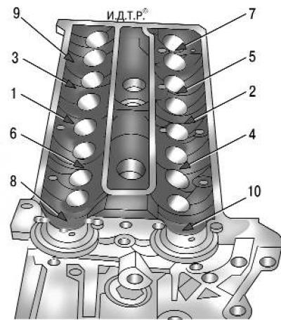
Fig. 5.7. Cylinder head bolt tightening sequence
– tighten the bolts on a cold engine in the order shown in Fig. 5.7, in three stages:
- Step 1 - Tighten to 15.0 Nm (1.5 kgf·m);
- Step 2 - Tighten to 30.0 Nm (3.0 kgf·m);
- Step 3: Turn it to a 90° angle.
32. Install all removed parts and assemblies in the reverse order of removal. After installing the camshafts and timing belt, check and, if necessary, adjust the valve clearances (see "Adjusting valve clearances").
33. Adjust the timing belt tension (see "Replacing the timing belt").
The text was obtained in its entirety from the specified website FordBook.ru